Week 8 - Challenge 6 - Core & Cavity Design
REPORT
- A detailed report should be done explaining the draft analysis and the tooling axis creation.
Draft Analysis is a tool that allows the user to ‘see’ whether the part they are designing can be removed from the tool being used to make it. In the case of plastic injection molded parts it also allows the designer to see if there is enough draft on the part to ensure that it can be correctly grained. I always use the tool with the axis direction method. Put the main axis on the draft direction line with Z being parallel to it. Select the tool then select the part body. You may need to reposition the axis again. The results window has 2 options 1 with just 3 colour variants and the other with many variants. They can be edited by double clicking on them to give you the result you desire. The colours show the different draft angles.
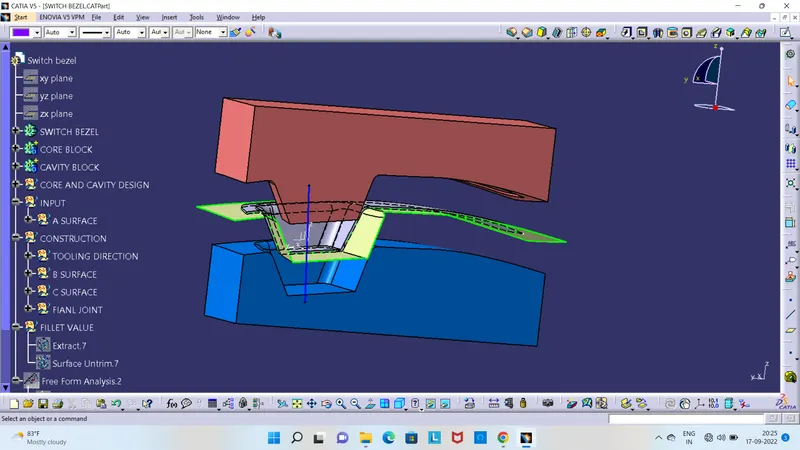
Tooling axis is the direction in which the the mold is open and closes. In other words, The Tooling Direction is basically the direction that the mold pulls apart. The mold is built in two separate pieces, basically. You have a Cavity side and you have the Core side. The Core pulls apart from the Cavity and that's the Dyeline or the Tooling Direction.
- An explanation should be given on the way of creating the tooling axis, particularly the Bisecting method.
For creating the tooling axis here we only have the three walls so create a boundary then draw the two referance line then take the bisect of the bothlie and make the two lines as reference.then create a boundary on the otherside and draw a line, here only one wall is present so we need to create another line normal to the plane with an draft angle of 4 degree. so that we get two intersecting lines and then create a bysecting lines with reference to this line and thus the tooling axis is created. Change the colour and thickness of the tooling axis