Week 8 - Challenge 5 - Core & Cavity Design
CORE AND CAVITY DESIGN
Objective:
To design the parting surface@ parting line and Core and cavity blocks for the switch bezel designed in the earlier challenge.
PROCEDURE:
For the core and cavity design of the switch bezal,the tooling axis and the class B,class c and solidbody is already created and draft analysis also already completed.
By using the same solid body and same tooling axis we create the core and cavity design.
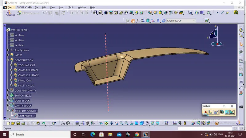
PARTING SURFACE:
Parting surfaces are used to separate the mold cavity from the core.
Designed for the removal of the plastic product and the cold slug, the parting surface is where the core meets the cavity, and usually locates at the largest section of a product.
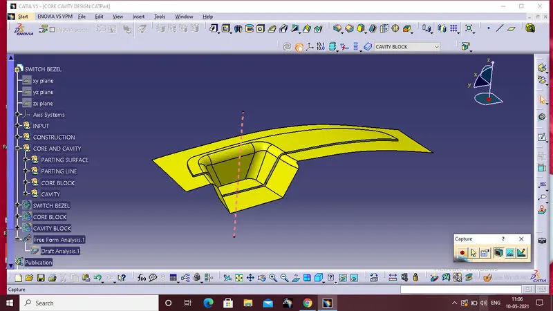
Fisrt extract theouter boundary of the class a surface and extrapolated at particular lenth.
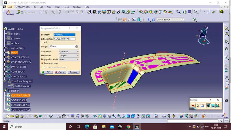
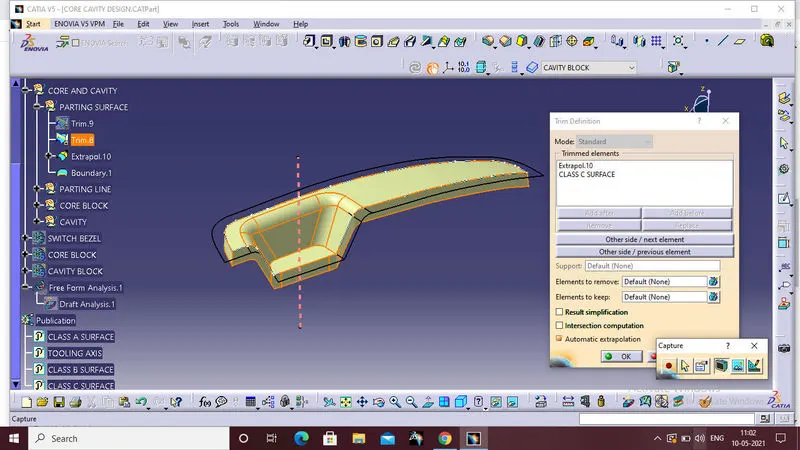
For parting surface creation first trim the extrapolated class A surface with class C surface.
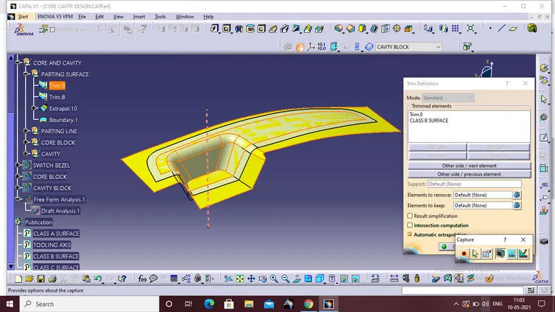
Than trim the class B surface with last trim surface that is the final parting surface.
PARTING LINE:
A parting line is the line of separation on the plastic part where the two halves of the plastic injection mold meet. The line actually indicates the parting ‘plane’ that passes through the part. Within more basic plastic part design plans this plane can be a simple, flat surface, but it is often a complex form that traces the perimeter of the part around the various features that make up the part’s outer ‘silhouette’.
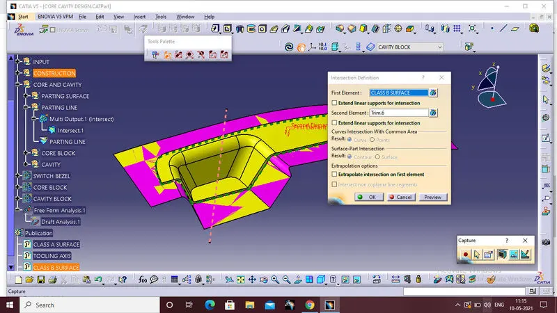
For parting line creation first intersect the class c surface with our parting surface.
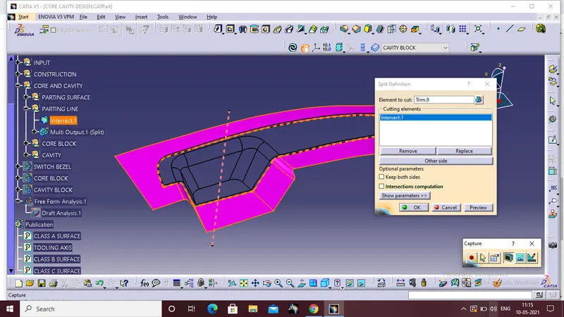
Than split the last intersection with our parting surface,that is our parting line.
CORE DESIGN:
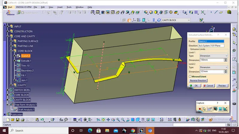
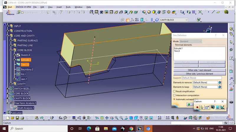
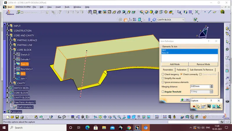
Than make the closed boundary at the top section and closed that boundary by using fill command,than finally join the top fill surface with core surface.
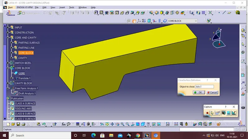
Finally make the surface core into solid body core by using closed body command that is in part work bench.
This is final core side half
CAVITY:
A mold is a hollow form typically made from stainless steel that has plastic injected into it to manufacture a plastic part. The plastic is inserted into the mold cavity, which is a hole in the mold shaped like the desired part.
Cavity block first draw the outer boundary than extrude the outer boundary of the cavity block.
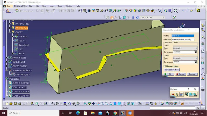
Than trim that surface with our parting surface
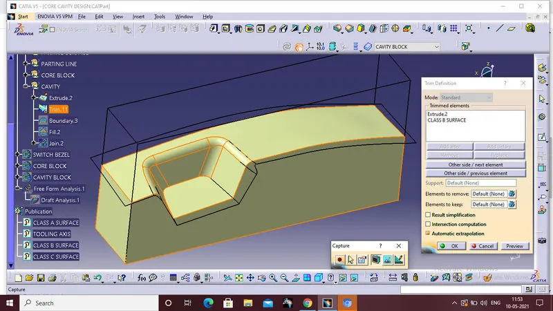 Finally close the bottom boundary by using bondary option than fill it the closed boundary with fill command and finally join with each other by using join command.
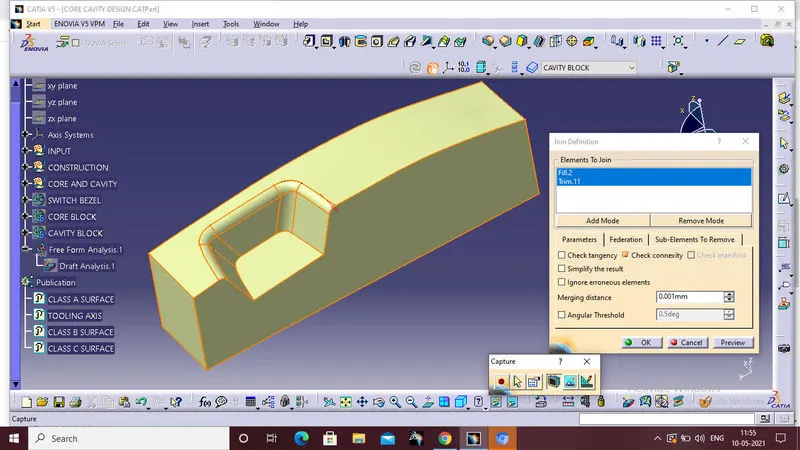
Finally make the surface cavity into solid body cavity by using closed body command that is in part work bench.
This is final cavity side half
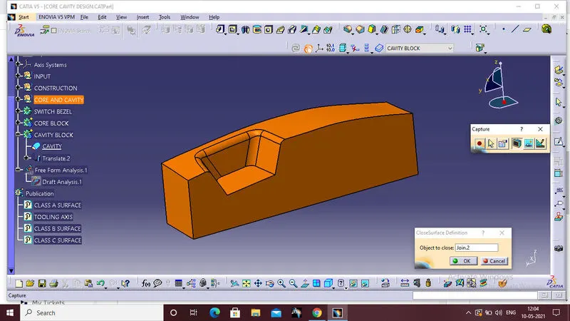
CORE AND CAVITY
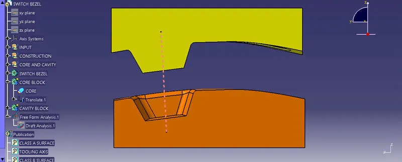
VIEWS:
FRONT VIEW:
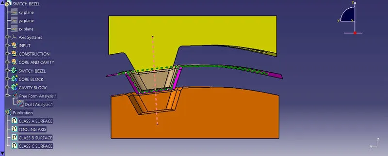
SIDE VIEW:
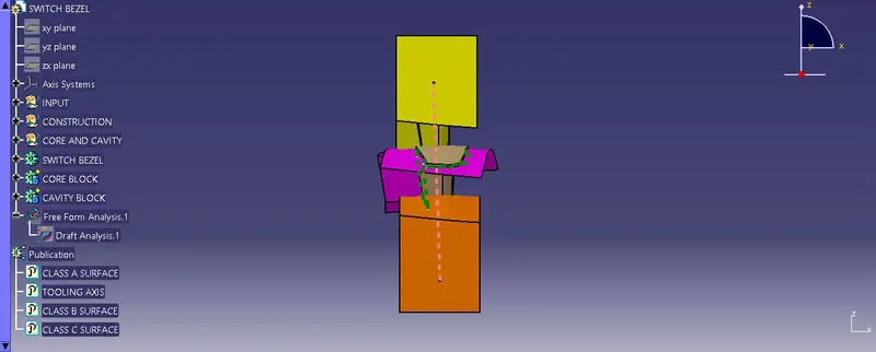
TOP VIEW:
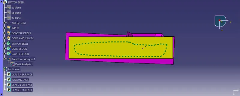
ISOMETRIC VIEW:
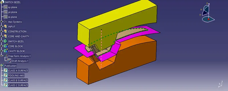
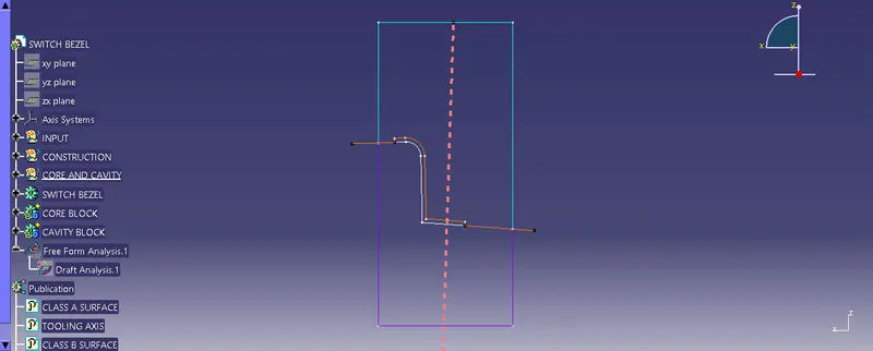
INTERSECTION VIEW OF CORE AND CAVITY,ORANGE LINE IS THE PARTING LINE
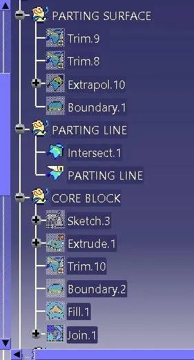
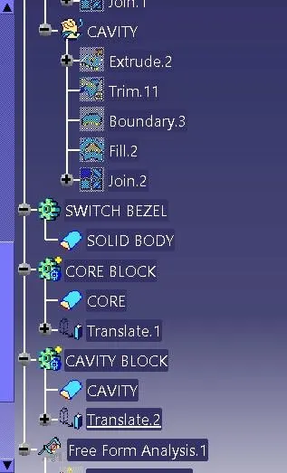
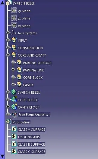
TREE STRCTURE:
RESULT:
To desinged the parting surface@ parting line and Core and cavity blocks for the switch bezel designed in the earlier challenge is compleletly done by using catia software.