Week 8 - Challenge 5 - Core & Cavity Design
CORE AND CAVITY DESIGN
Based on the previous design of Switch Bezel, Now I'll Design the Core and Cavity for this plastic component.
- First I'll need to check the Core and cavity portion for the Switch Bezel. I can find this out by performing a draft analysis on the plastic components.
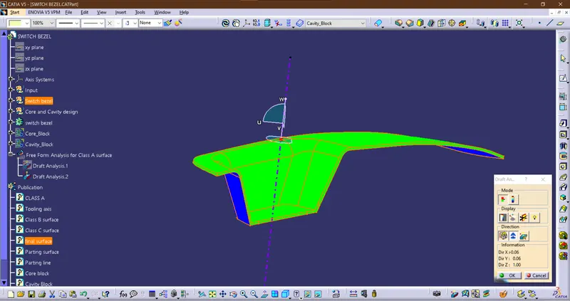
now by the performed Draft Analysis, it is clearly observable that the surfaces which are green will be considered as Core Side tooling direction. And the Blue surface will be Considered as a Cavity side tooling Direction. Because the core mold has a shape where the surface converges outwards like the Convex type. And the Cavity mold has a shape where the surface converges inwards.
- Then I have to create the parting surface for the plastic component in the position where the core and Cavity meet.
to find this out I viewed the part from the top and the surface edges which are visible at the boundary will be my parting surface boundary.
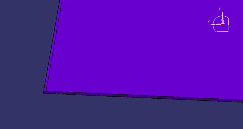
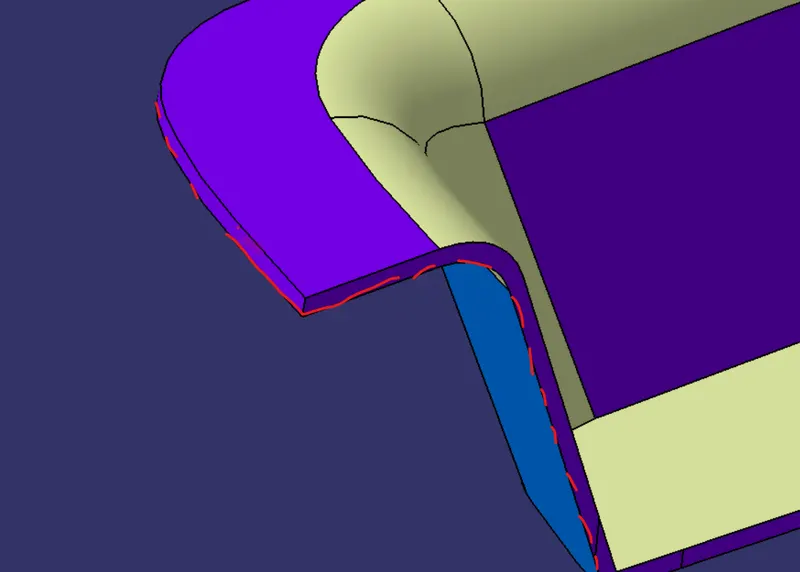
or we can find the parting point where the green surface ends at the corner.
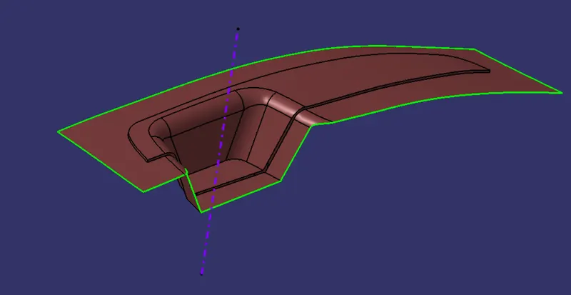
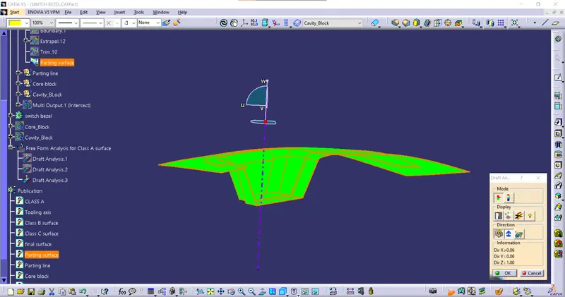
Parting Line is Hileted in red
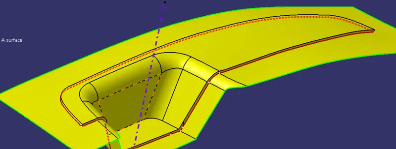
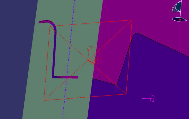
- Now for the Core and Cavity Block, I'll create a rectangular sketch that will be inside the Green boundary which is shown above.
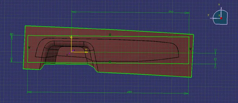
this will be my core and Cavity boundary.
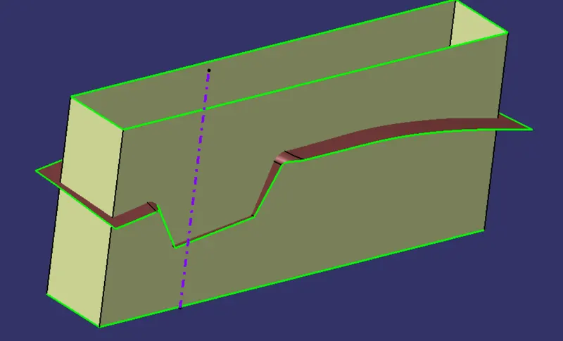
CORE BLOCK
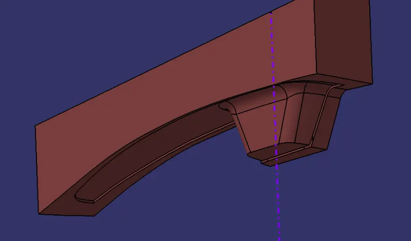
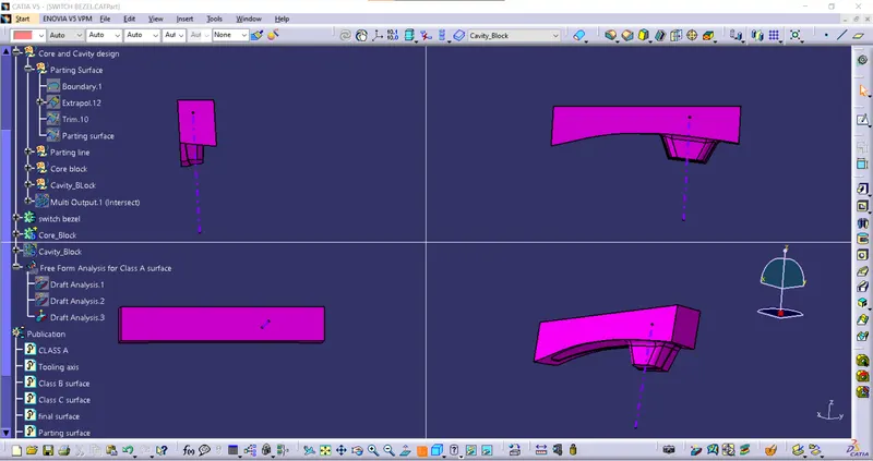
For the Cavity block, I'll trim the class B surface and cavity surface.
Cavity Block
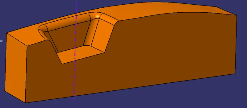
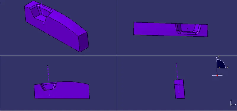
Actual Method and placement
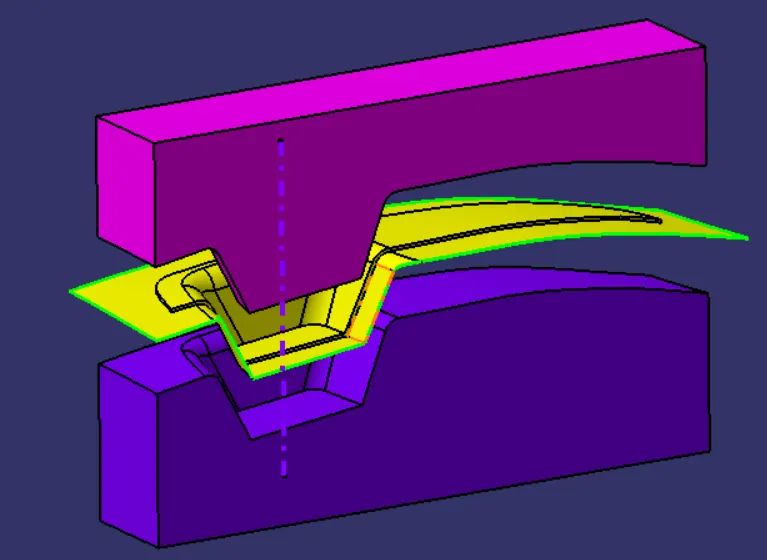
Cross Section of Core and Cavity blocks together