Week 8 - Challenge 4 - Bumper
BUMPER DESIGN
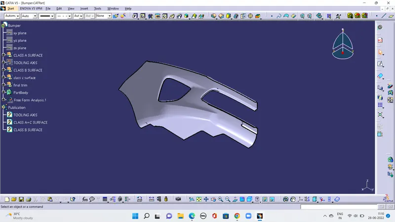
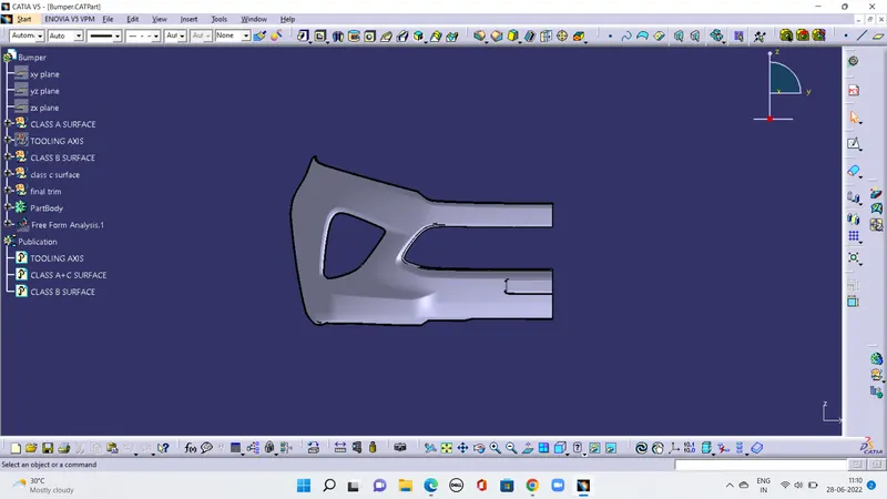
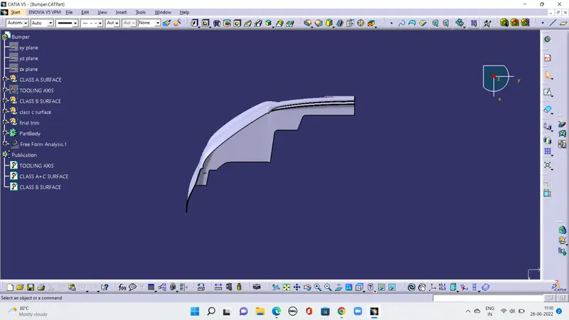
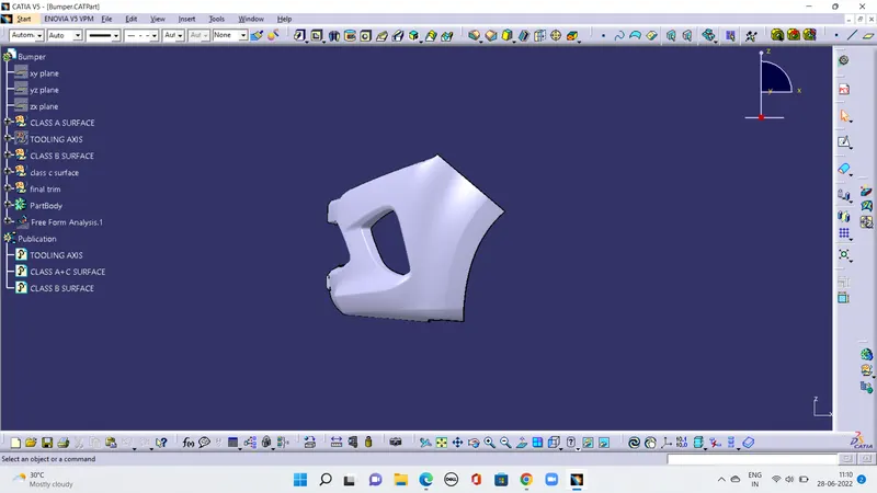
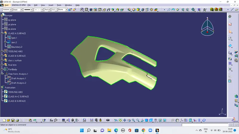
AIM: to make a model from the provided class-A surface.
INTRODUCTION:
CLASS-A SURFACE: a surface made by the designer which is given as an input to the plastic modeler to work on. It is aesthetic surface
and the outer most surface.
CLASS-B SURFACE: a surface below a certain thickness from the class-A surface is class-B surface. This is the surface that contains
engineering aspects of a model.
CLASS-C SURFACE: a surface that joins class-A and class-B surfaces is class-C surface.
METHODOLOGY:
In this model we have focused on the following things:
Tooling axis
Draft analysis
Class-B surface
Class-C surface
Making a solid model from surface.
Following tools were used to reach the final step:
Extract
Un-trim
Trim
Extrapolate
Offset
Edge fillet
Boundary
Sweep
Join
Close (part design)
FOR DRAFT ANALYSIS:
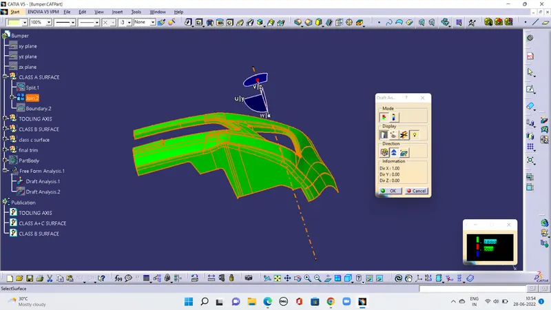
First we analysis the model and then choose dummy axis in x and y direction.
As we intersected to proceed we observed that the side walls are not given any draft. Hence we assume the axis normal to the base surface and parallel to side walls. This surely will create problems because a minimum draft has to be provided.
As class-A surface is made by other designer only he is authorized to make changes, so we look over this to complete the coin holder for practice.
Now we go to insert< analysis< draft analysis and follow usual procedure to do the analysis.
Align the compass and click on the surface and as expected the model is mostly in red color i.e. negative draft with respect to the axis.
To correct it to as best as we can we moved the compass a bit till we got most of the surfaces in green and lock that position.
After hitting ok, we change the direction of the line from z axis to compass direction. The axis will align itself accordingly.
NOTE: as the side wall does not have draft, this result was expected and few areas need correction. But still we are moving forward to
complete the model
FOR CLASS-B SURFACES
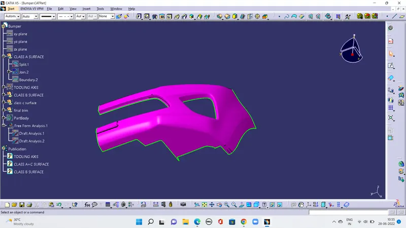
We have divided the entire model into base, side walls, inside side walls and outer flange and worked on them one by one
Everywhere we follow same procedure i.e. extract, un-trim, extrapolate, trim and offset.
First base, then side walls. To avoid confusion, we trimmed both together and made them one. Also the fillet was given.
FOR CLASS-C SURFACES
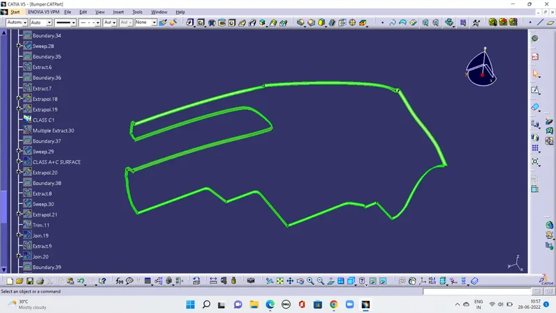
In this model, unlike the earlier models, we have used parallel tooling axis. Hence we cannot use ‘with draft direction’ option under
sweep.
The C surfaces will mostly be created like shown below.
FOR FINAL MODEL
Join class-A and class-C surfaces together.
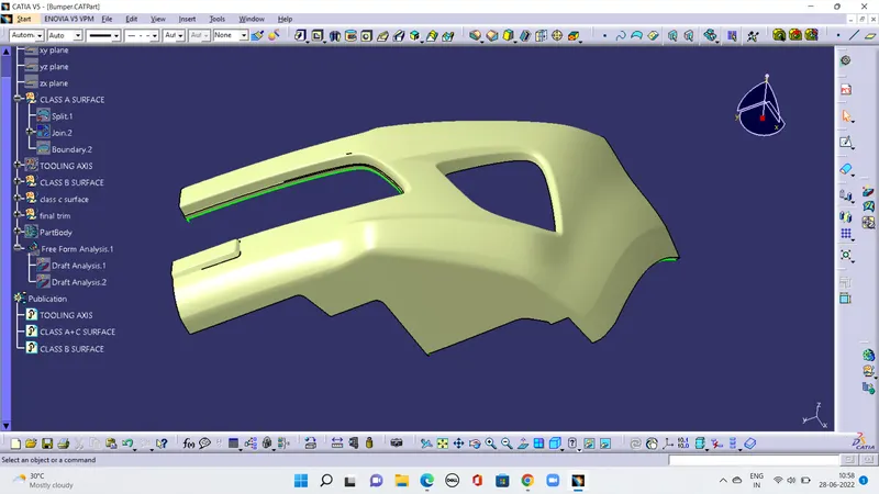
Then Trim class-B surface to them.
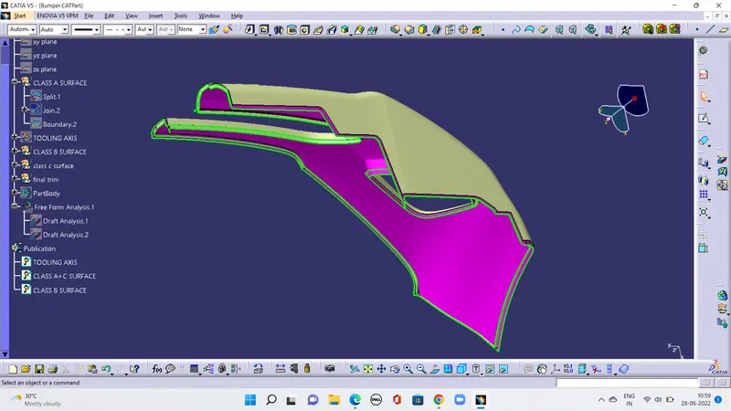
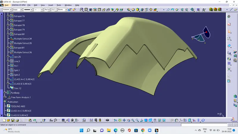
Go to the part design and close the feature.
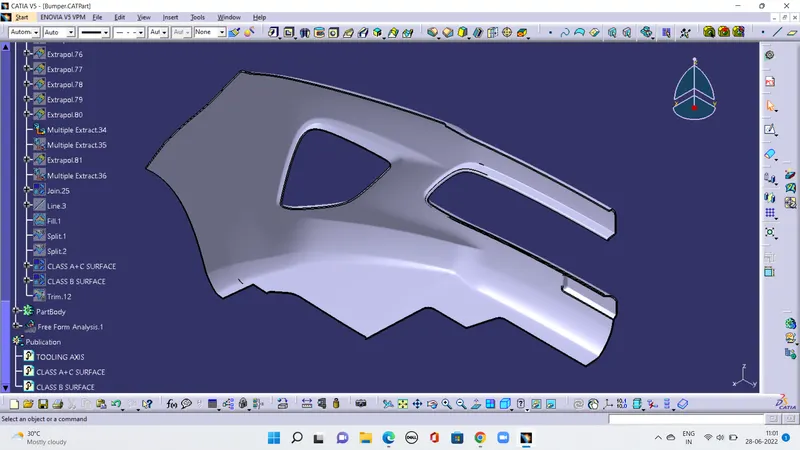
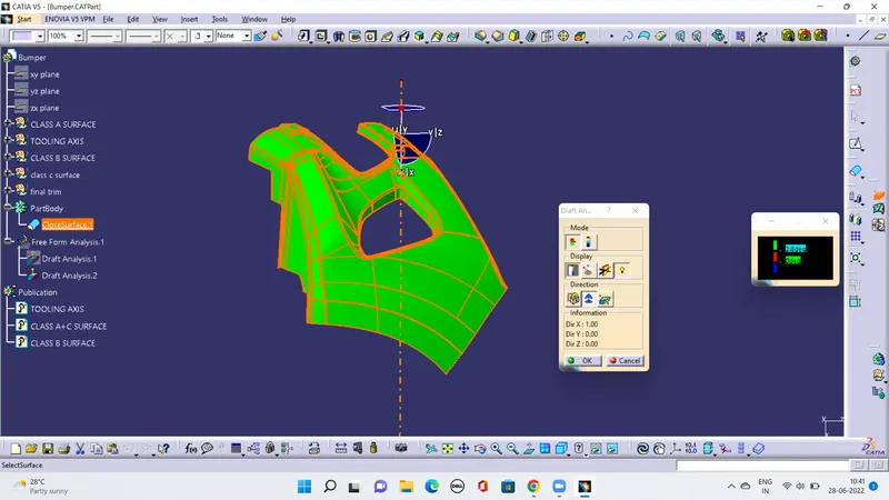
Run draft analysis on the model.