Week 8 - Challenge 4 - Bumper
BUMPER
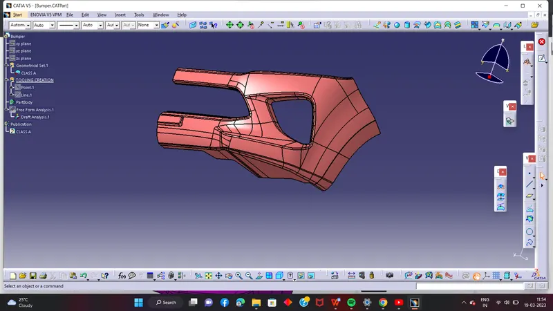
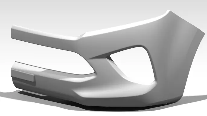
CREATION OF BUMPER BODY FROM CLASS A
CLASS A
AIM :
To create a body of Bumper from the input given which was the A-surface of a Bumper. The created body should be a closed solid volume which should be feasible for manufacturing and Tooling. The draft angle and draft analysis of the component should be done.
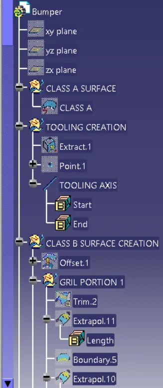
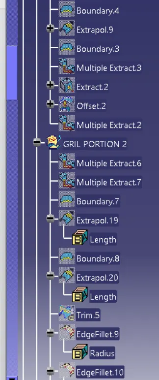
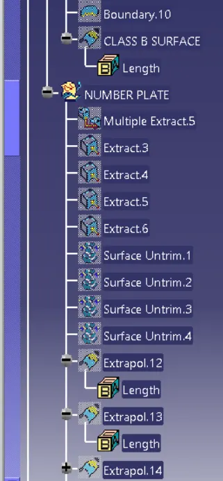
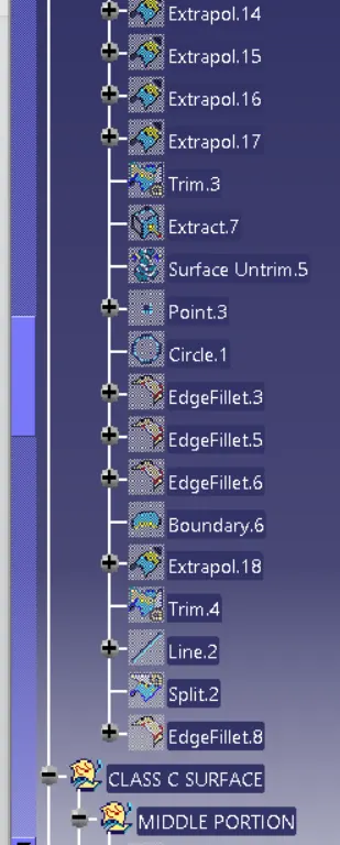
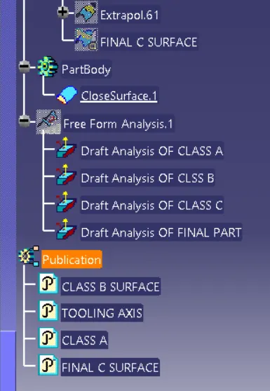
In model, proper tree structure to be maintained and publications of Tooling axis,A,B and C surfaces to be done.
INPUT GIVEN:
A-Surface
Thickness of component is 3.00mm
Draft angle is 3 degrees.
CHECKING THE INPUT - A SURFACE:
The A-surface or the styling surface is first checked for any gaps and other issues in its surfaces. This Surface acts as the input surface so any correction to be done should be with approval from the styling team or done by them. A- perfect surface is the one when a boundary is created, the lines are only on the edges of a component and its holes or cutouts as shown below.
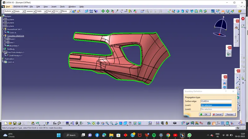
While creating a boundary there is no boundary gap that means A surface is fine
CREATION OF TOOLING AXIS:
Tooling axis is the direction in which a core or cavity of mold opens. This Axis is very important to determine the orientation of the component in mold, core and cavity design.
The tooling axis is created by the inertia method by using the steps as follow
* Click “Measure inertia” and select the A-surface
* Click “Create geometry” in the Measure Inertia window.
* In the Creation of Geometry window, select Non-associative geometry.
* Click “Center of Gravity”
* The Inertia point is created.
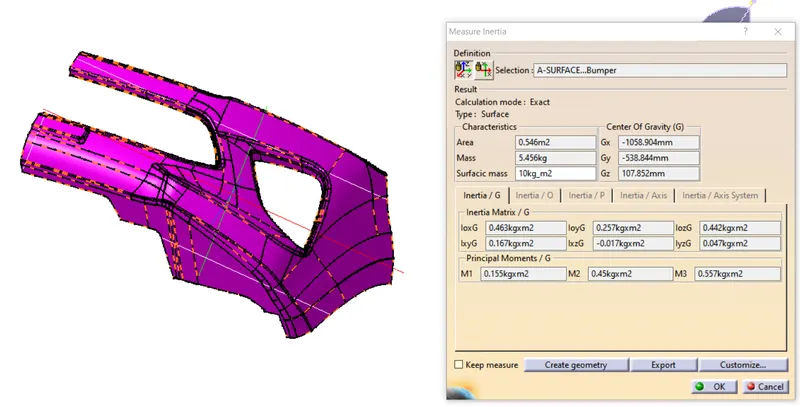
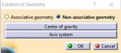
Image 2 : Creation of Inertia point
* The component is viewed in all axes namely X,Y and Z.
* It is determined that the X-axis will be the direction for the Tooling axis and a line is created Using the CG point and X-direction as direction of the line.
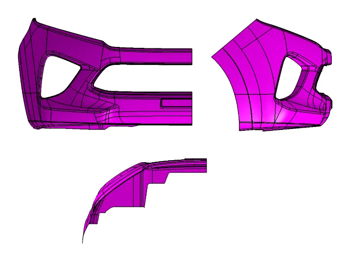
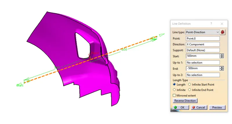
Image 3 : Creation of Tooling Axis
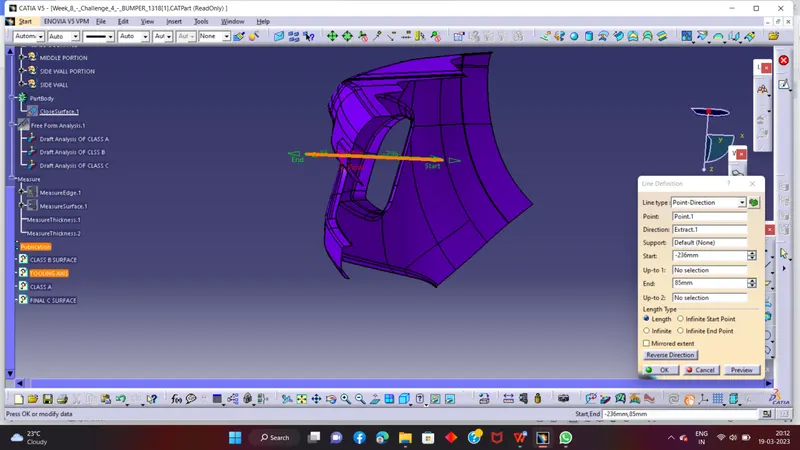
Another method is You can create tooling axis simply creating the point on class a surface and draw a line with point direction option like ahown in the below pictures
DRAFT ANALYSIS OF A SURFACE:
Draft analysis of the surface is carried to check if the surface or part can be manufactured with the required draft angle.
Draft angle is needed for the component to clear the core and cavity surface as it would have shrunk towards the center while cooling.
The draft angle in this design is 3 degrees. As A surface is a single surface there won't be much difference in color. The draft analysis of A-surface is shown below. (See Image 4 and 5)
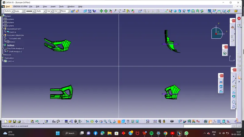
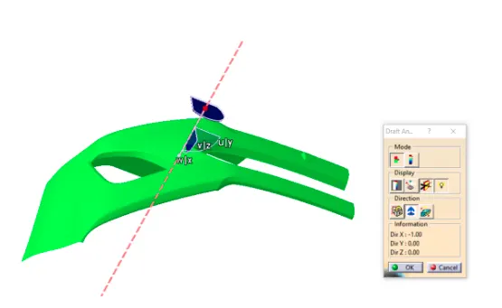
Image 4 : Draft analysis of A-surface
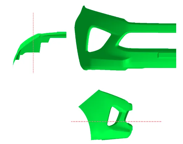
Image 5 : Draft analysis of A-surface , different views
CREATION OF B-SURFACE :
The A-surface is offsetted by 3.00mm as it is the thickness required.
The offset surface is the B-surface but had some issues like in some areas shown in below images.
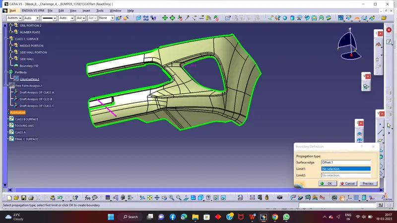
There are lot of boundary gaps so I have to fix it using different different operation like ‘multi section surface’ ‘sweep’ ‘extract and extrapolete and trim’ after all of fixation we ot the final b surface
FINAL B SURFACE
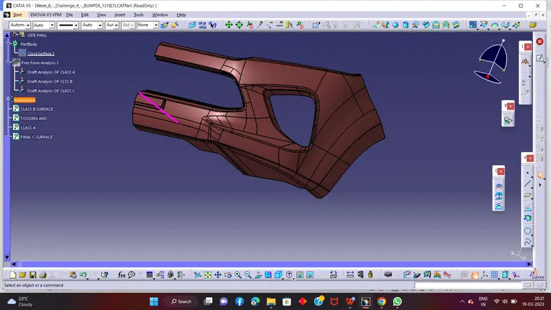
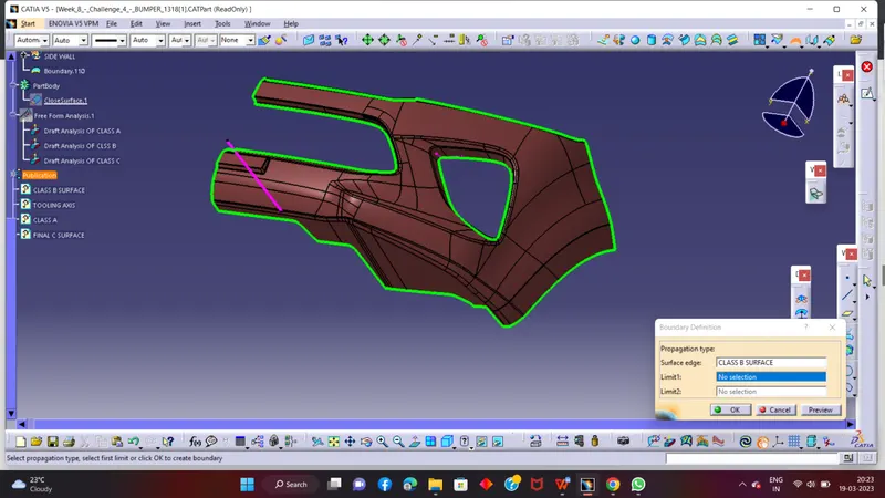
In this image you can see that there is no boundary gap that means the b surface is completey fine
SURFACE-C Creation
Surface that joins class-A and class-B surfaces is class-C surface. Class C is often specified for interior surfaces not readily visible, surfaces that will be covered by another part when assembled
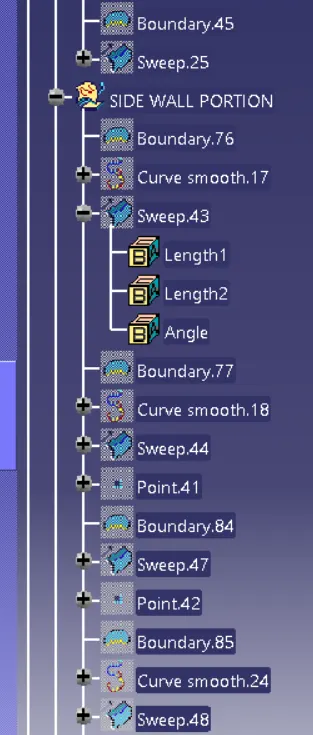
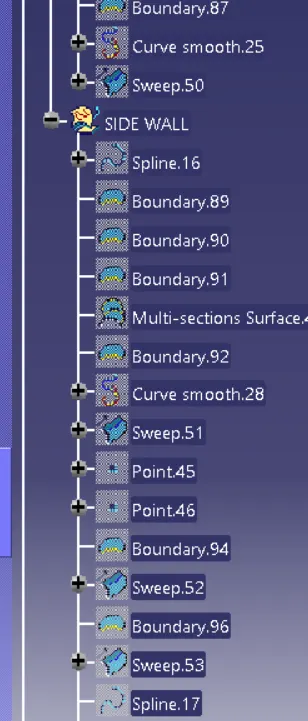
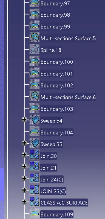
Since it is a complex class-A surface, we cannot simply create the class-A boundary curve and sweep it at one shot. Hence, we need to create smaller curves using multi-extract command and then create sweep of 90 degree with reference to the surface option. sweeps at the midportion of the bumper should have a 93 degree vaue to pass the draft analysis.
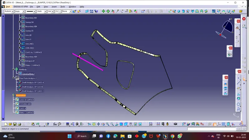
Creating the final surface of Bumper
First step is to join the CLASS-A surface with CLASS-C surface.
Then Trim the Joined surface with CLASS-B surface to achieve the final Bumper surface.
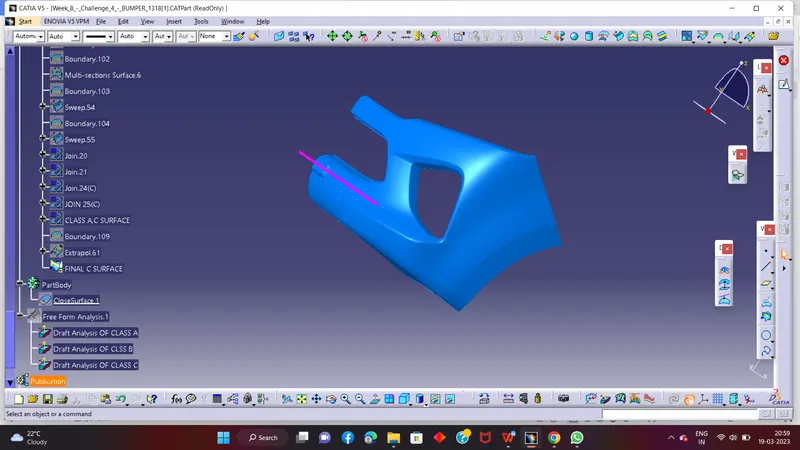
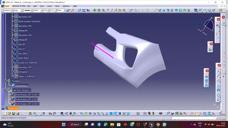
Go to the part design work bench and using the close surface command create the base bracket solid part body
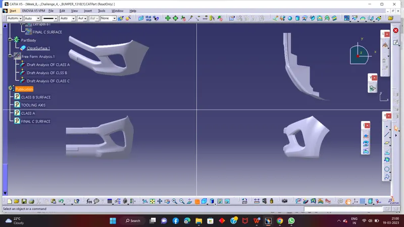
3D Part model in various orientations (Isometric, Front, Side, and Top View)
DRAFT ANALYSIS OF FINAL PART
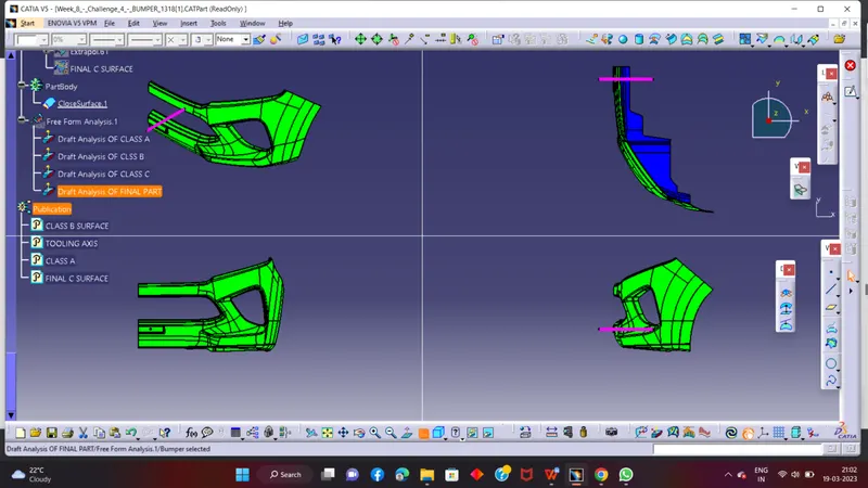
The expanded Tree Structure for the geometrical set and the Part Body