Week 8 - Challenge 3 - Switch Bezel Design
Switch Bezel Design:
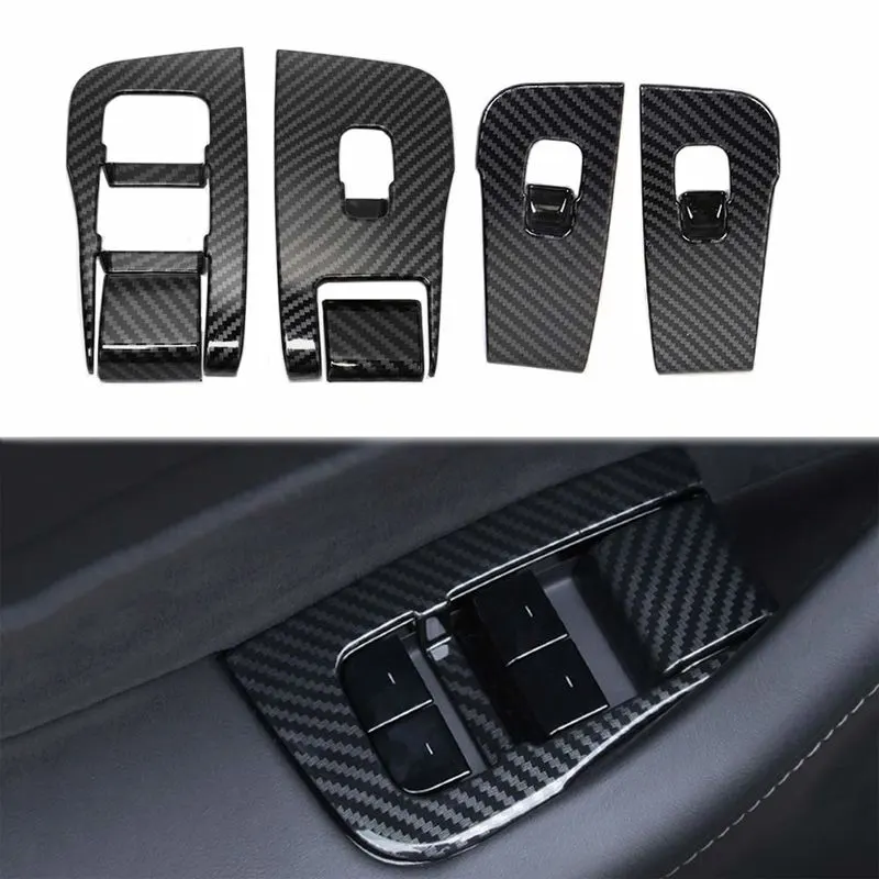
Switch Bezels in car are parts which contains switches and controls for different functions like Window control, Door lock/Unlock,Media and Temperature controls.
This A-surface of this part is derived from scanning a clay model and B,C surfaces with other engineering features are developed as per specifications and inputs.
This challenge is to create an closed solid body by forming the B and C surfaces from the given A-surfaces. Draft analysis of both surface and the solid body needs to be done to determine the moldability of the
part.
Inputs:
A class A surface was given to develop the part. (See Image 1).
Thickness of the part is 3.0 mm.
The draft angle is 3 Degree.
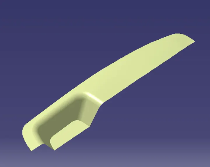
Image 1 : A-surface of Switch Bezel
Tooling axis:
After analyzing the A-surface in three directions namely X,Y,Z directions it was determined that Z direction will be best for tooling axis as it was clearing all the surfaces and the pocket.
The measure Inertia tool was used to find the center of surface and point was created and based on that point a line as created in Z-direction. (See Image 2 and 3)
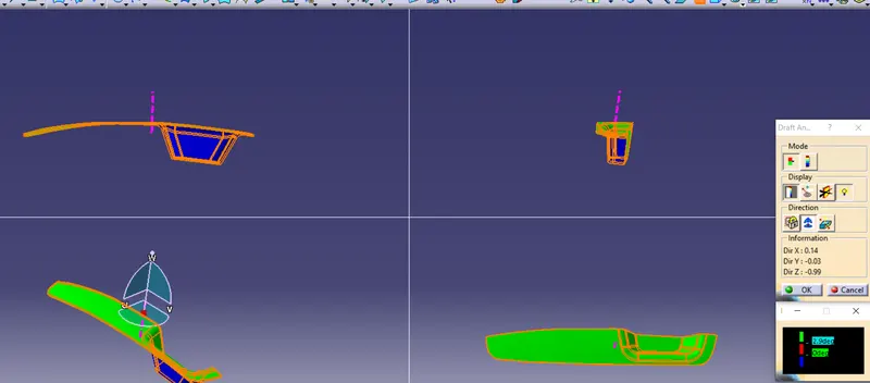
Then Using draft analysis ,it was checked if all the surface clears the draft angle of the 3 degree.
In this case, One surface was in Red and was not clearing. So, the compass was adjusted by selecting the "W" in Z direction to make it clear. The X,Y,Z position of compass were noted and the same was inputed
in the line's X,Y,Z direction by changing its directions from "Z-direction" to "Components" (See Image 4 and 5)
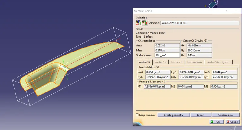
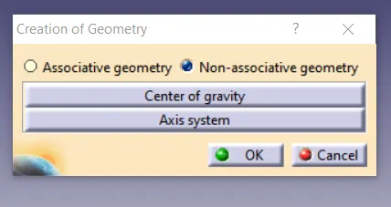
Image 2 and 3 : Finding Inertia Point
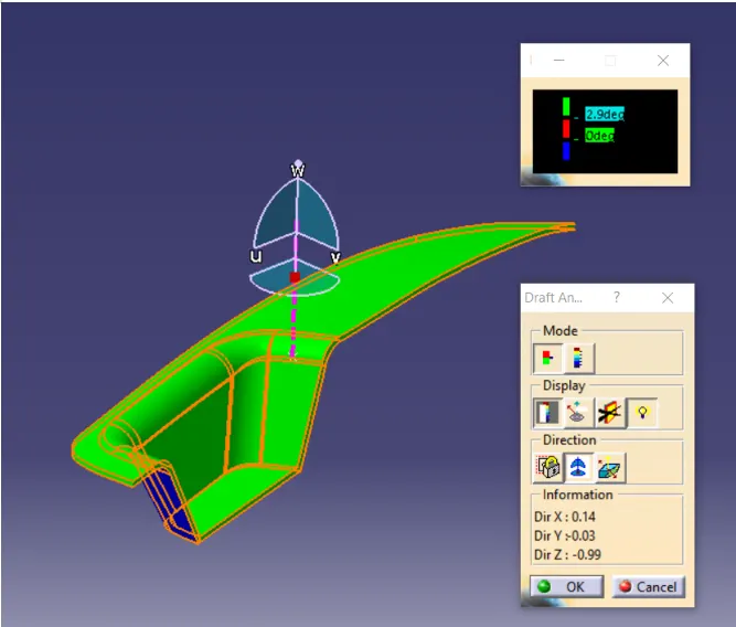
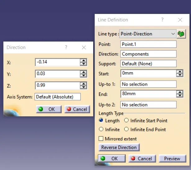
Image 4 and 5 : Adjusting the compass to achieve the draft and inputing X,Y,Z values in the line created earlier
B-surface:
The next step was to create the B-surface. The A-surface without the radii were selected and extracted. These surfaces were the untrimed. (See Image 6)
These surfaces were then trimed together and offsetted to a thickness of 2.5 mm and the radii for the pocket were given. Thus the B-surface was created. (See Image 7)
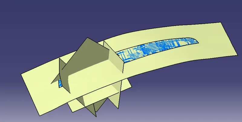
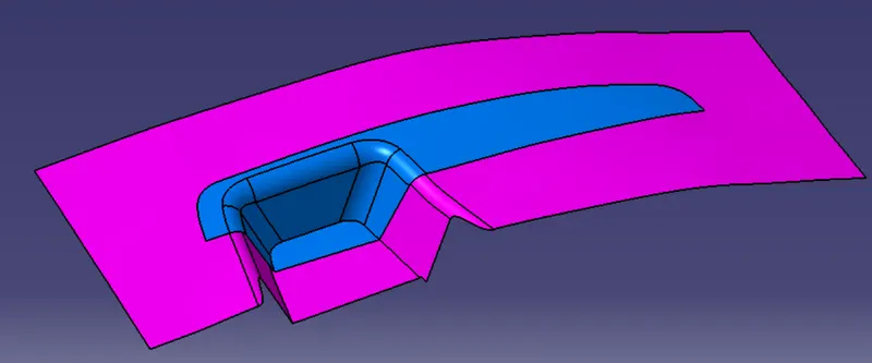
Image 6 and 7 : Different steps involved in creation of B-surfaces
C-surface:
C-surfaces are created using the boundary of the A-surfaces and sweep with draft direction is used to create the surface. The Boundary and an angle of 3.0 degree is given as input.(See Image 8 and 9)
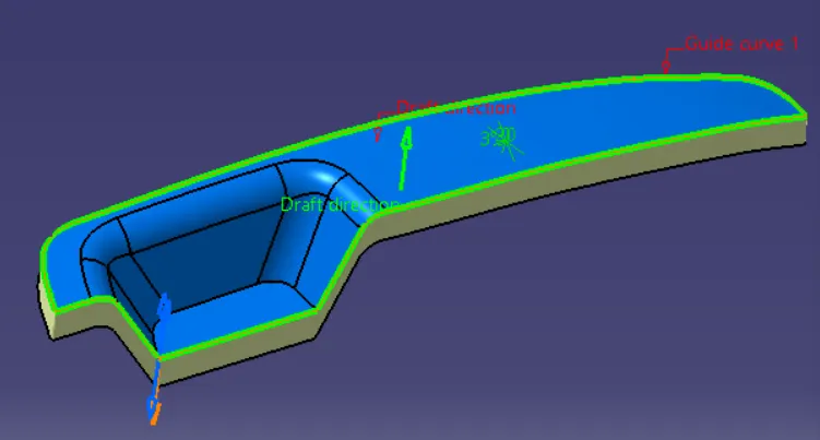
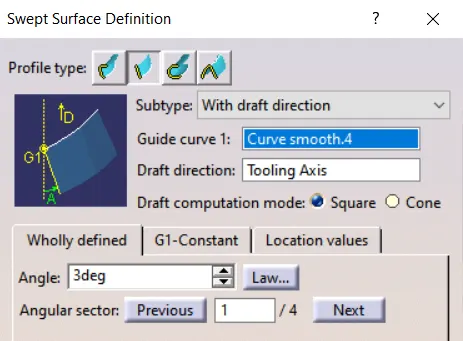
Image 8 and 9 : C-surface creation using Sweep option with draft direction
Final trim and closed Body:
All the three A,B and C surfaces are trimmed together to form a closed body. To check for any gap, the body was selected for creating a boundary but error window showed up which meant
it was closed body.(See Image 10 and 11)

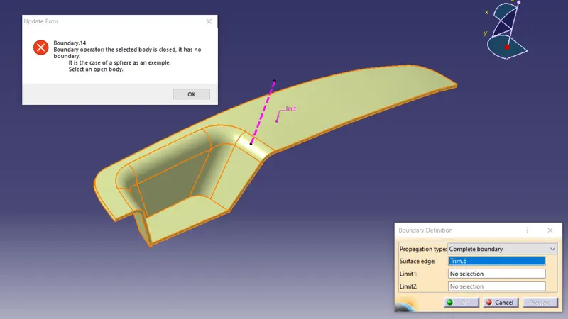
Image 10 and 11 : Closed surface body created and checked using Boundary option
Solid Body:
In part design workbench, A part body was inserted and using close surface option in surface related features, the solid body was formed by selectin the final trim. (See Image 12)
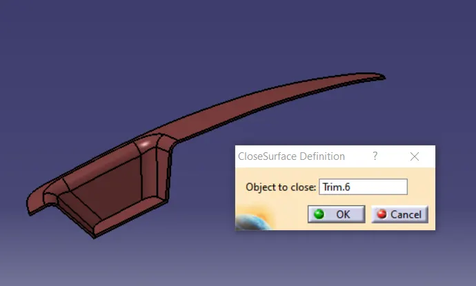
Image 12 : Solid body created using close surface
Publication:
All surfaces were plublished as shown below for easy access while working in the model. (See Image 13)
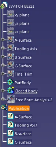
Image 13 : Publication tree shown at the end
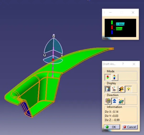
Draft analysis of part:
The draft analysis was done for the part also by following the same procedure as done for A-surface.
It was concluded that part is as per the required draft angle and can be ejected without any issue. (See Image 14)
Multi-view: