Week 8 - Challenge 3 - Coin Holder Design
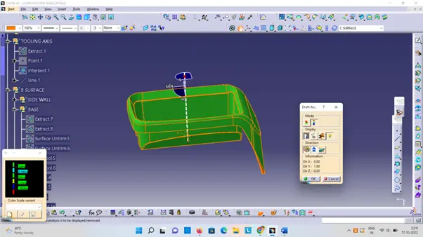
AIM: Create the Coin Holder Plastic component through the given Class-A surface. To begin with, the tooling axis for the given Class-A Surface should be created meeting the requirements of the draft angle and at the end perform the Draft analysis on the model.
Take the Thickness of the component to be 2.5 mm.
Tooling Axis:
It is the direction in which the component will be ejecting after the molding process is completed.
The direction of tooling axis should clear the maximum portion of the part.
Generative shape design
Point
Line
Extract
Extrapolate
Join
Trim
Offset
Boundary
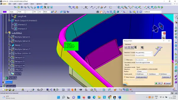
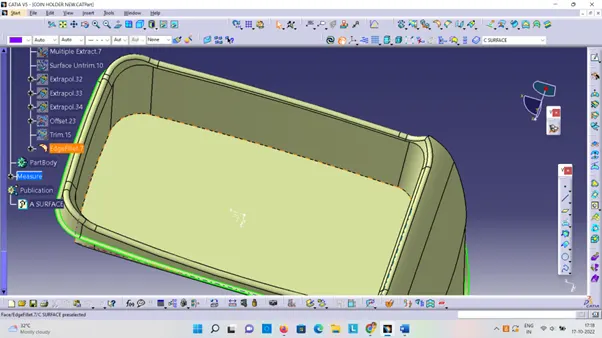
Edge fillet
Intersection
Sweep
Feature Draft Analysis
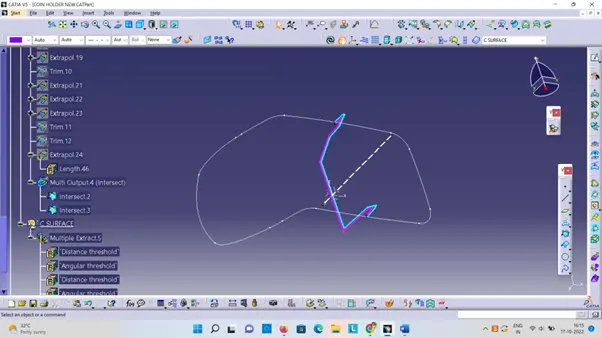
Tooling Axis creation:
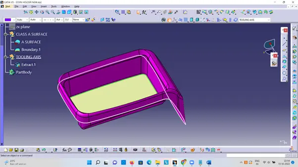
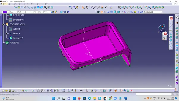
First, we will extract the base surface of class ‘A’ and on that create the point and then create Axis system at that point.
As these surfaces are complex and cannot clear the tooling axis. In this situation we need to communicate with class ‘A’ designer and here we are doing this just for practice purpose.
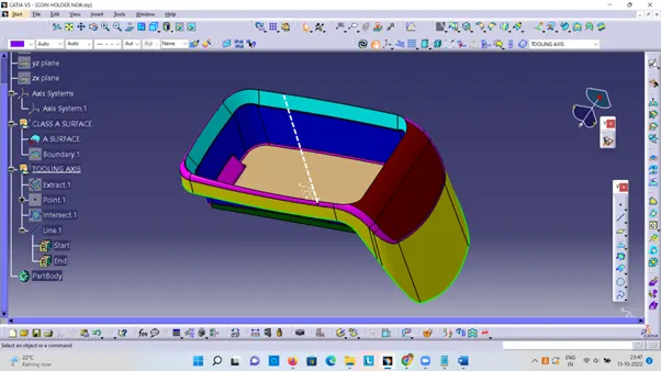
So that we are creating the tooling axis in Z direction.
This line is the Main tooling axis for our part.
After which we will be publishing the tooling axis and class ‘A’ surface.
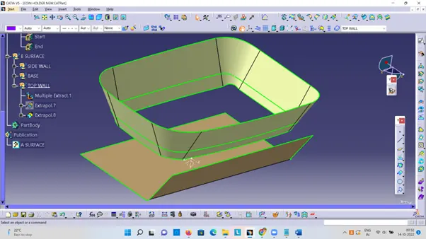
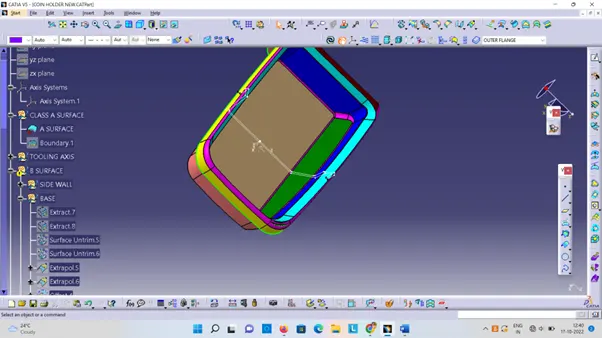
‘B’ Surface Creation:
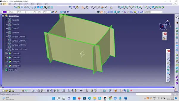
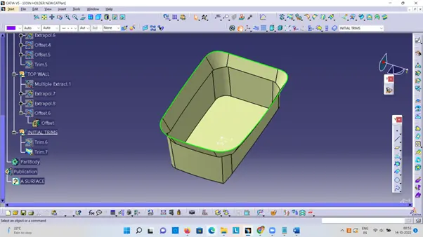
Extract Class ‘A’ Surface.
Untrim extracted surfaces.
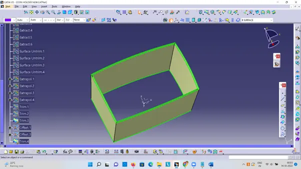
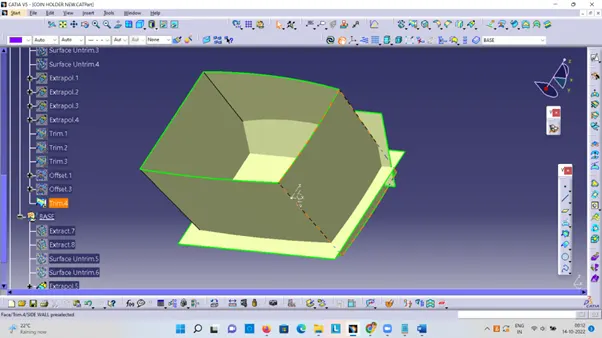
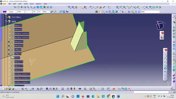
Use trim and select proper surface.
Offset inward at 2.5 mm
‘C’ Surface Creation:
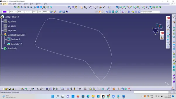
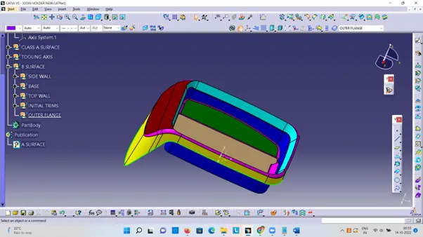
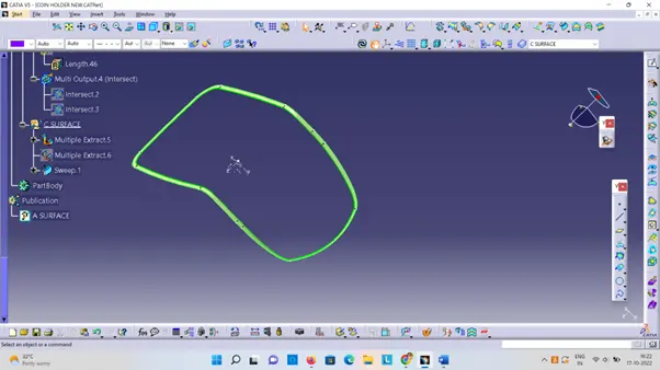
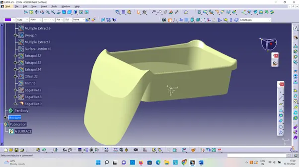
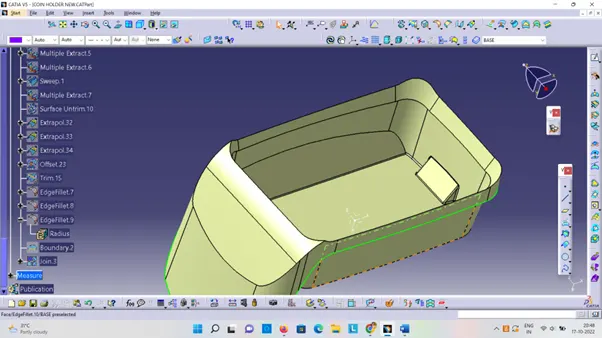
Take outer boundary using Boundary command of class ‘A’ surface
Also extract the outer surface for reference purpose.
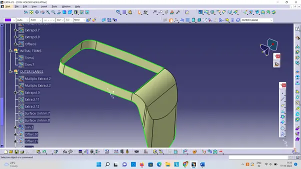
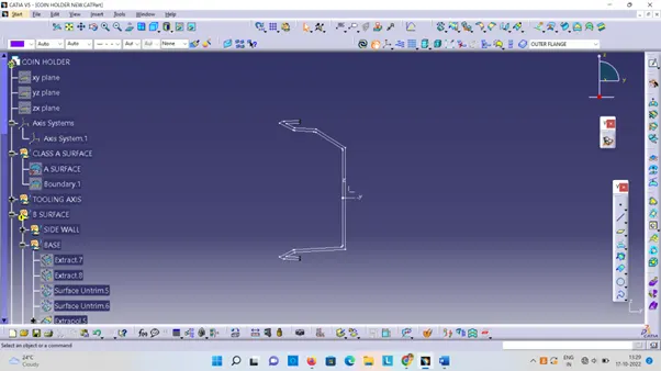
Use sweep command to create surface using the extracted boundary and the reference surface.
Give the sweep surface angle as 90 degree and extend the surface up to 3mm and select appropriate direction.
Sweep – profile type ‘line’ – subtype ‘with reference surface’
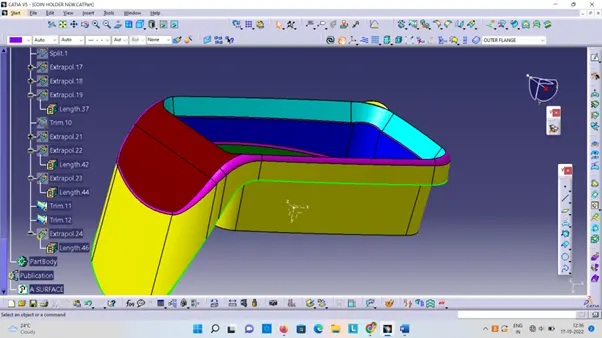
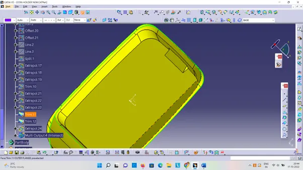
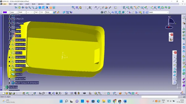
Final Body creation:
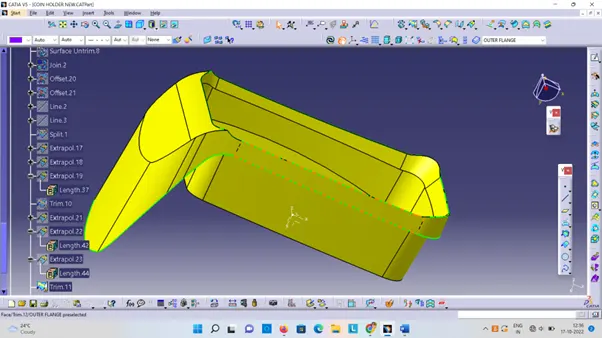
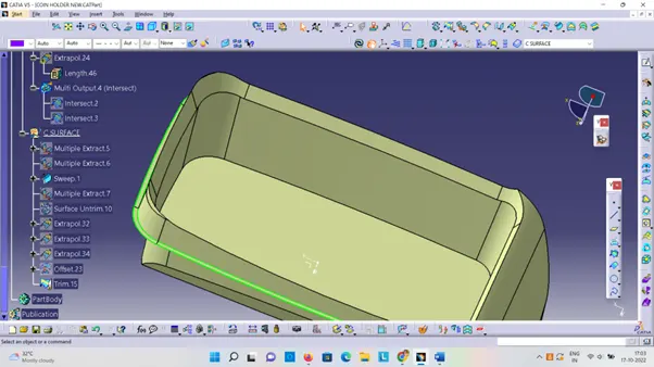
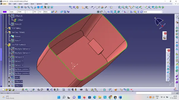
Join class ‘A’ surface and ‘C’ surface.
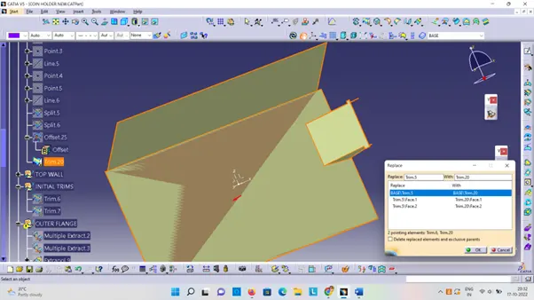
Trim resulting surface with ‘B’ surface.
Join the surface
Final Draft analysis,
Below Steps are followed: