Week 8 - Challenge 3 - Coin Holder Design
NOTE - MY CAT FILE DOES NOT OPEN SO I AM USE THE STEP FILE
AIM : To create a Coin Holder plastic component through the given Class A surface and perfoming the draft analysis on the model
objectives :
- To ensure proper tree structure is followed
- To keep the design as per requirement
- All the sketches should be iso constrained
- To publish the Class A,B and C Surface.
PROCEDURE :
- First import the class A surface in catia.
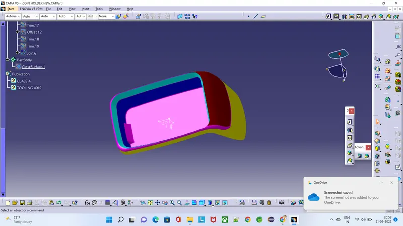
-
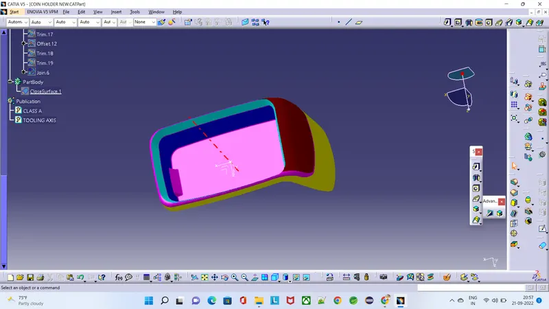
Creation of Tooling Axis-
In this part CCS (Class C surface) will be at 90deg to the part ejection direction/ tooling direction.
- Creation of close surface using Class A, B & C surfaces-
a. Creating Class A surface (CAS)-
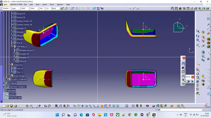
- Creating Class B surface-
Class B surface will be holding all engineering features like ribs, screw bosses, etc.
We need to create CBS (Class B surface) using CAS (Class A surface). The process of generating CBS is explained below-
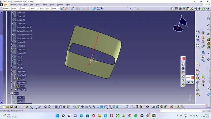
- CREATING THE SIDE WALLS OF COIN HOLDER
For this part tooling axis will be normal to the bottom face. Process to create tooling axis is explained below-
- CREATING THE BASE OF COIN HOLDER
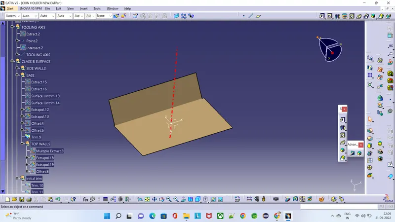
- CREATING THE TOP SIDES OF COIN HOLDER
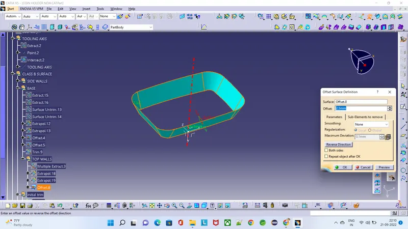
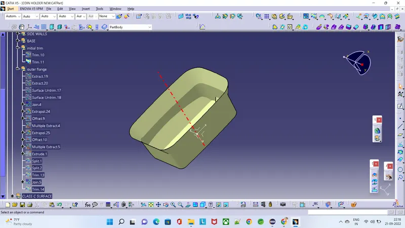
- CREATING THE OUTER FLANGE OF COIN HOLDER
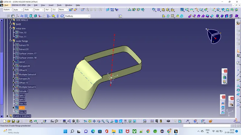
- TRIMMING THE BASE & SIDE WALLS
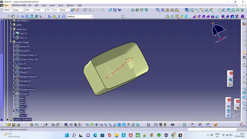
- TRIMMING THE TOP SIDES & THE BASE WHICH TRIMING BEFORE
After creation of class A, class B and class C surfaces, now we trim class b and class c surface to forma a new thick surface part, and then join the trimmed surface with class a surface to form the final required surface.
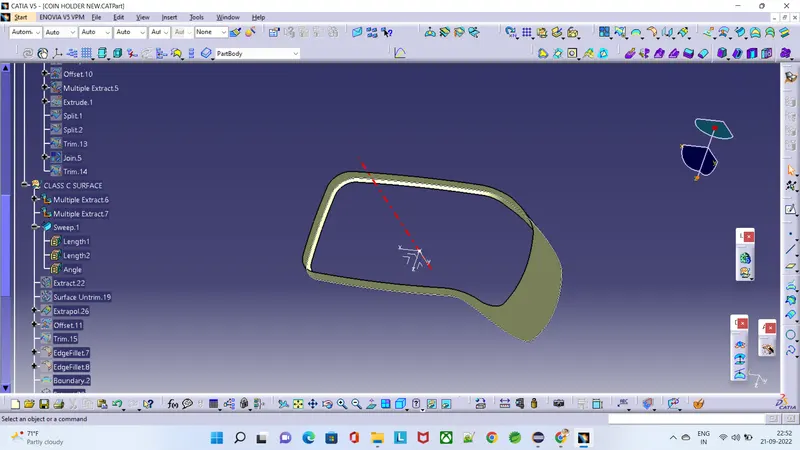
- CREATING THE CLASS C BODY
NOW USING THE CLASS A SURFACE BOUNDARY, CREATED THE SIDE OF THE WALL AT 90 DEGREE OF 4MM.
-
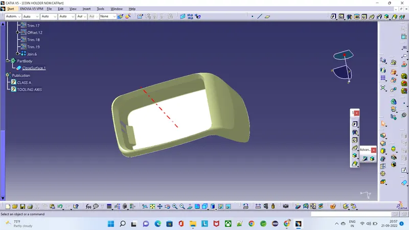
Creating solid surface from closed surface
Creating solid body requires completely closed surfaces or otherwise it will show error.
Using close surface command in part workbench we have created solid body & edge fillet will applied
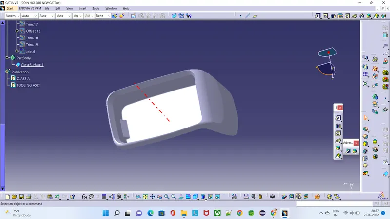
Draft Analysis-
Process of performing draft analysis in Catia V5-
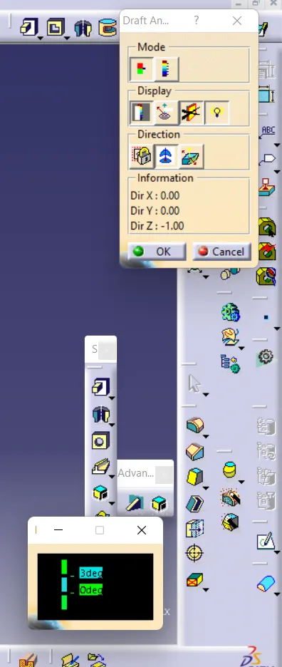
1. Click on the draft analysis icon ( ) or go to Insert>Analysis>Feature Draft Analysis.
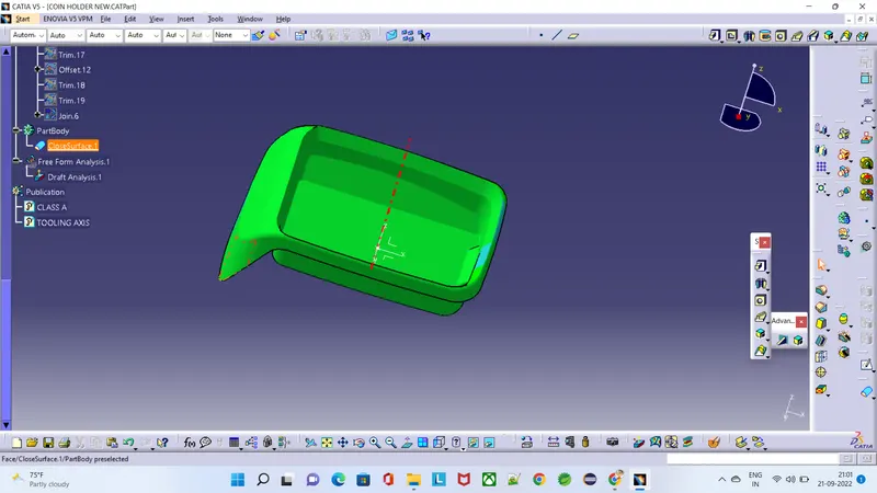
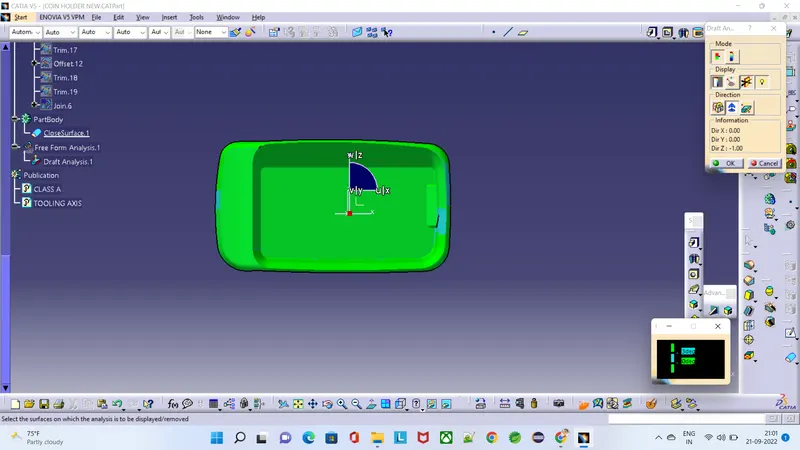
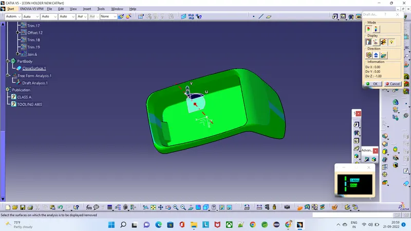
2. Draft Analysis will highlight the entire area of the model with different colour codes according to the rage of angle they have with the draft direnction. In this model we have set the green colour for angle more than 3 degree. Blue for the angle between 3 to 0 degree. And red for angle less than 0 degree.
3.For the ease of manufacturing we always preffer minimum of 1.5 degree. When it reduced further the complexity of manufacturing increases and thus the cost increases. If we require some undercuts then we need to use side cores.
- Conclusion-
1. We have understood how to generate class B & class C surfaces from input class A surface
2. We have understood importance of Tooling Axis
3. We have understood importance of Draft & Draft analysis
4. We have created solid body using closed surfaces.