Week 8 - Challenge 3 - Coin Holder Design
COIN HOLDER
AIM:
Creating the coin holder plastic component through the A-class surface and add thickness to it
Objective :
Creating the B and C surface
Creating the tooling axis
Performing the draft analysis on both A surface and final plastic components.
Take the Thickness of the component to be 2.5 mm
Introduction :
The input of the product designer is in the form of the A-class surface. The job of the product designer is to create the B and C surfaces keeping all the aspects for the mold.
Class A is
1.Visible surface and aesthetic look
2.surface with textures
3.Surfaces provided by customer(OEM)
4.Don't have any features like(rib, snap, bosses, etc) on class A surface.
5.Class A surface is made from scanned data with different software like alias etc.
6.Surfaces which are having CURVATURE CONTINUITY IS CALLED class-A.
Class B surface:
1.invisible Surfaces.
2.Surface mostly don't have textures
3.Surface needs to be created according to the class-A surface.
4.having all features(Rib,boss,snap etc) in B-side surface only.
- Surfaces which is having TANGENT CONTINUITY IS CALLED class-B
Procedure :
Creating the tooling axis :
The tooling direction is used to find the direction in which the part is ejected out of the mold or it is the direction in which the core and cavity are moved and the part is ejected.
The draft on the part should be positive in order to manufacture the part easily. The draft angle should be positive with respect to the tooling direction.
* To create the tooling axis, we need the proper orientation or view that gives the correct features and draft available in the component.
* So here the component view from the Y-direction gives the proper view for the tool to see the features present in the geometry.
* To create the tooling axis from the Y direction we need the tooling axis from the other direction that gives the wall draft angle.
* The bin base center will be the initial tooling axis for the coin holder.
The tooling axis created by following steps
1 The base surface is extracted.
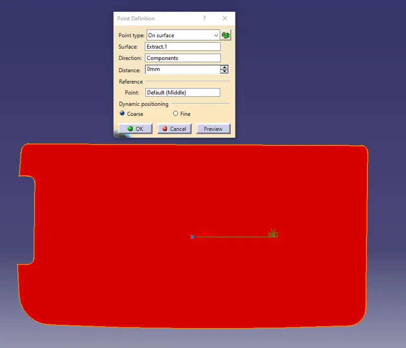
- Then the center point is created using the point > on the surface at 0
- At the point created the axis system is created.
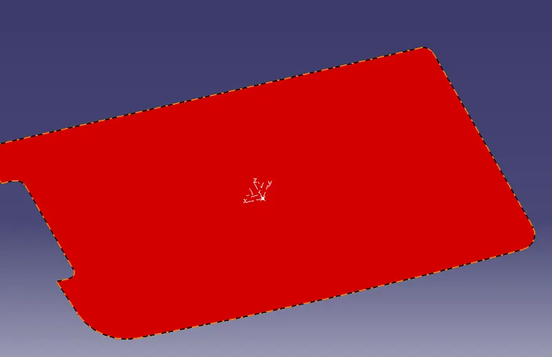
After that switching the view of the model to the X direction and creating the tooling axis.
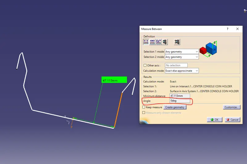
Using the intersect in the ZY plane to get the boundary lines. Then the lines are created along the slant surfaces.
Here the wall lines form the zero degrees angle with the base. So the final tooling axis will be perpendicular to the base or in the Y direction from the center point.
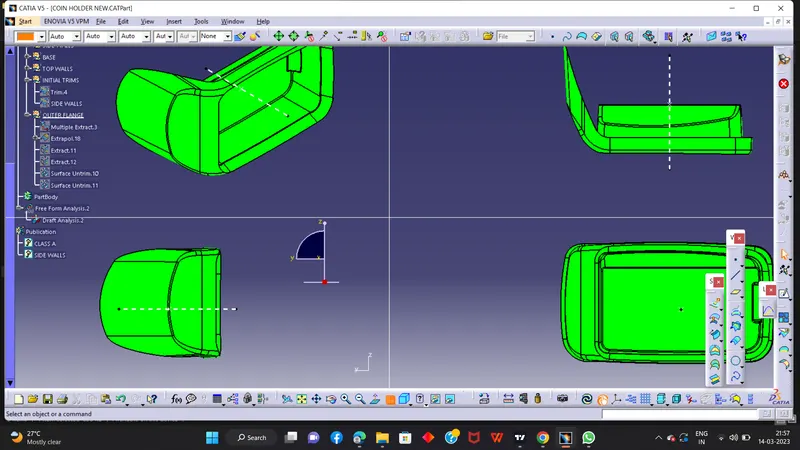
DRAFT ANALYSIS FOR CLASS A
CLASS B SURFACE CREATION
* First, extract all 4 surfaces of the sidewall of the coin holder.
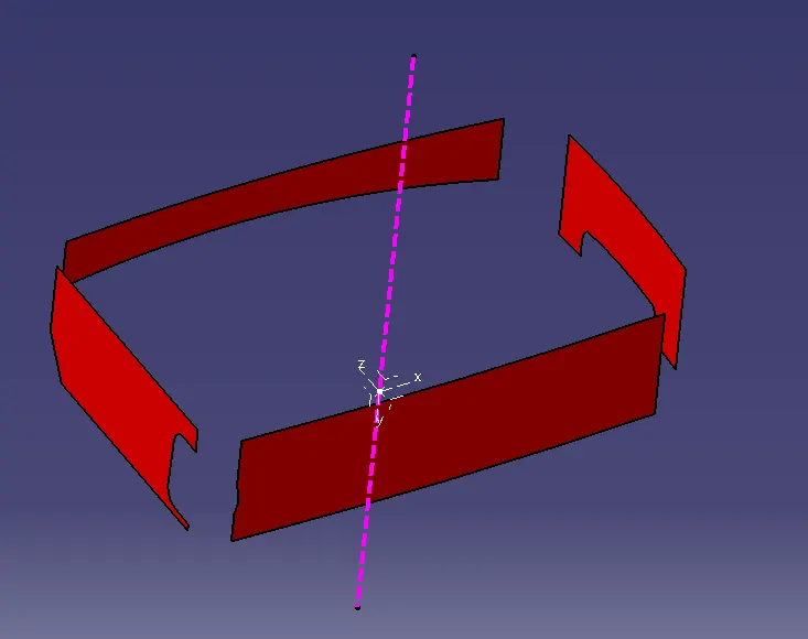
* If the surfaces are not intersected, then extrapolate by point continuity propagation is used to make these surfaces have an intersection between them
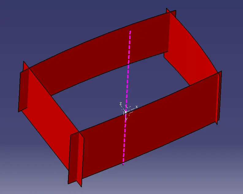
* Lastly, the surface trim is used to get the replica for the inclined surface.
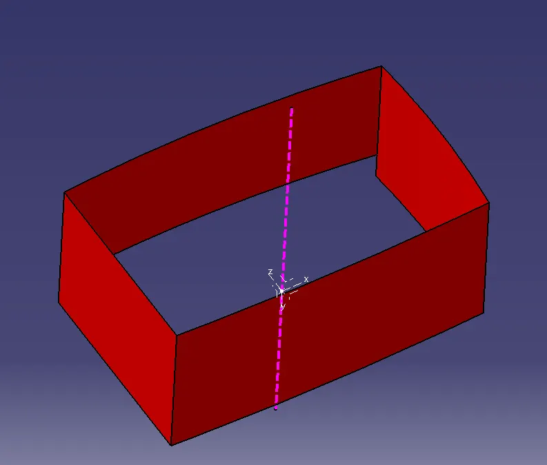
* Now, the thickness of the final component is 2.5mm so this obtained surface is offset below by 2.5mm.
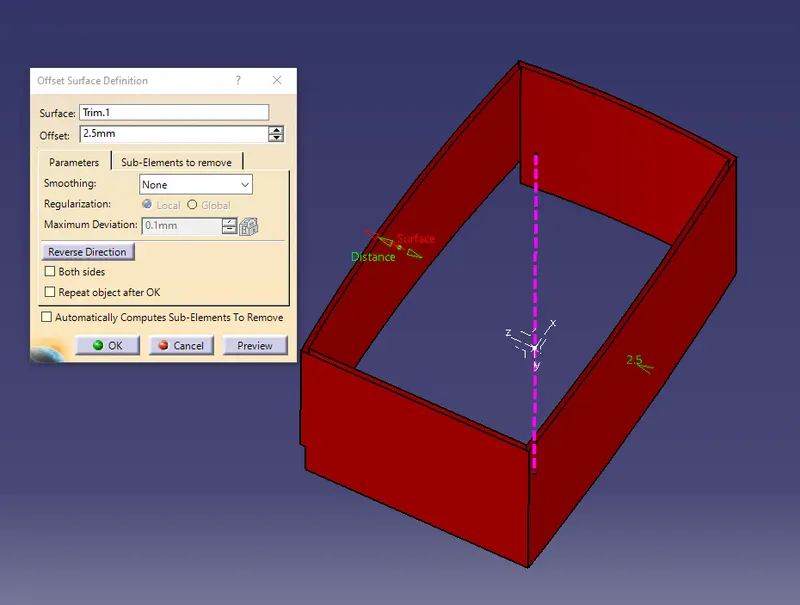
* Like that the rest of the region is extracted and trimmed to get the final B surface.
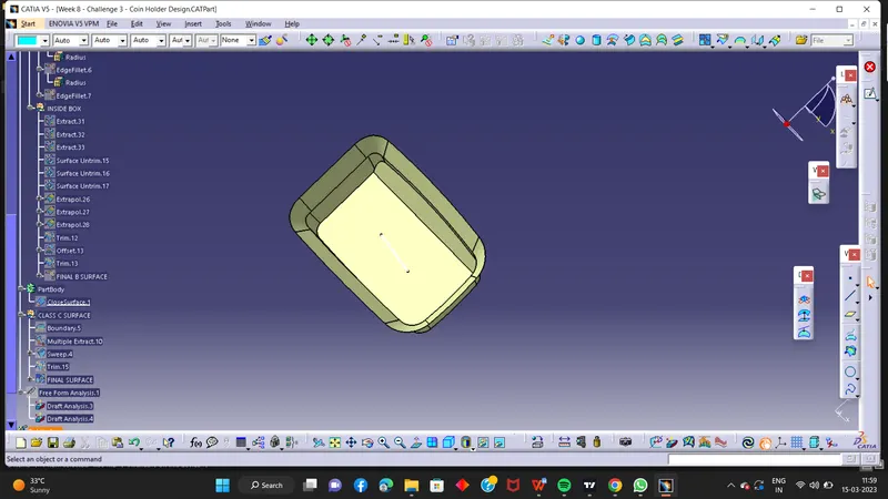
FINAL CLASS B SURFACE
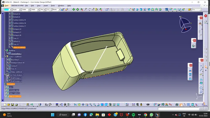
C-class surface
* C class is where the thickness of the component can be seen.
* For the C surfaces, the boundary is extracted from the A surface and then swept with a reference surface in 90 degrees inside
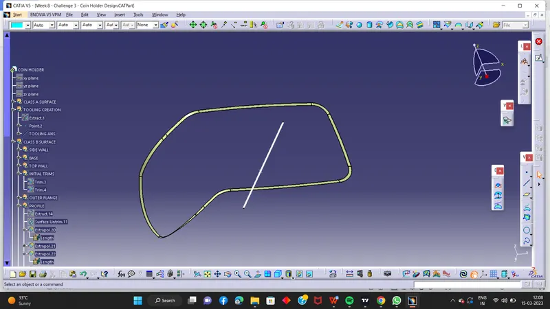
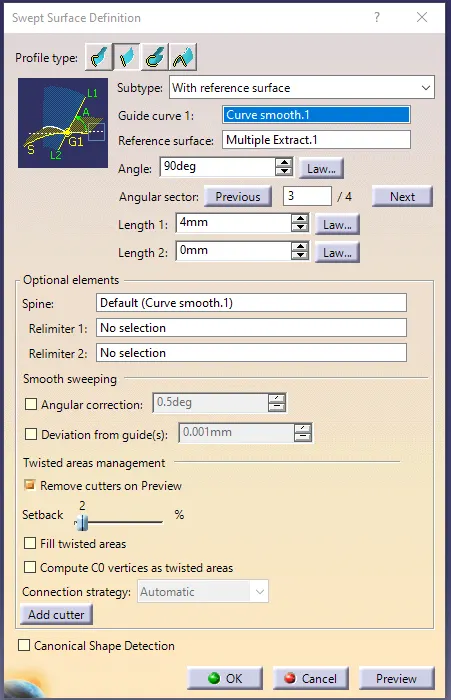
* Next, the swept surfaces are trimmed with the B-class to form a complete B and C surface.
* Lastly, the BC is joined with the A surface to get the final coin holder component. This obtained surface is then thickened in part design.
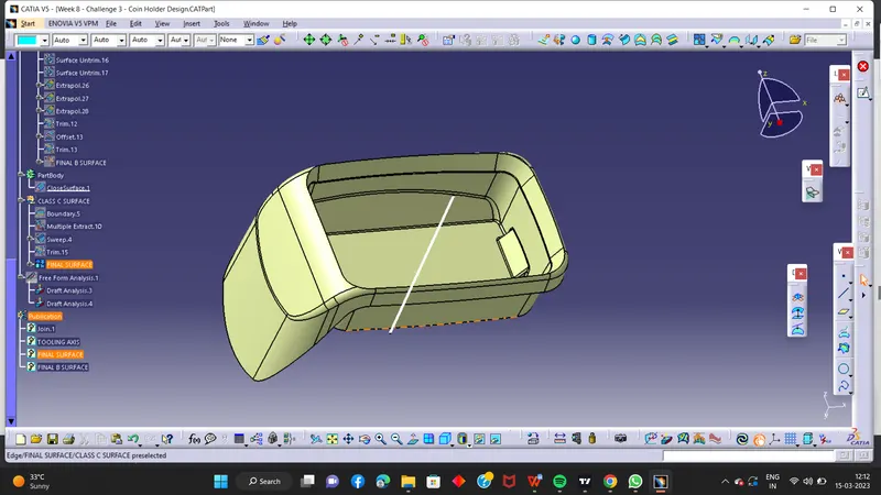
Results :
Final coin holder plastic component :
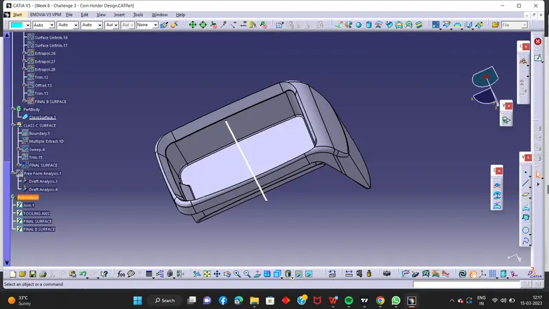
FINAL PRODUCT DRAFT ANALYSIS

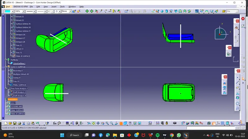
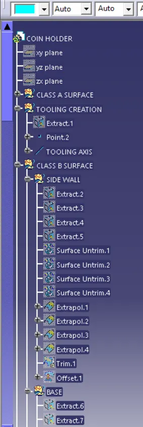
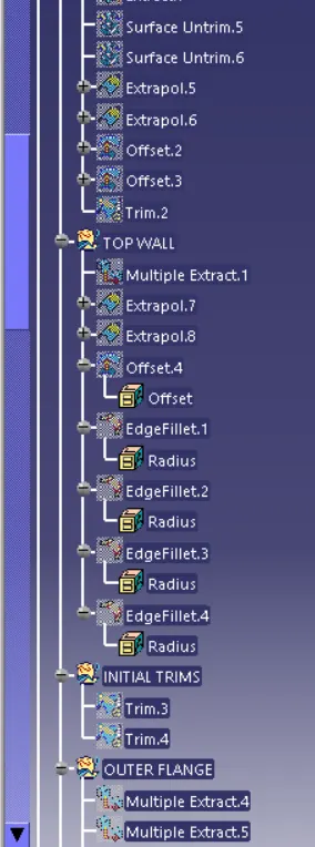
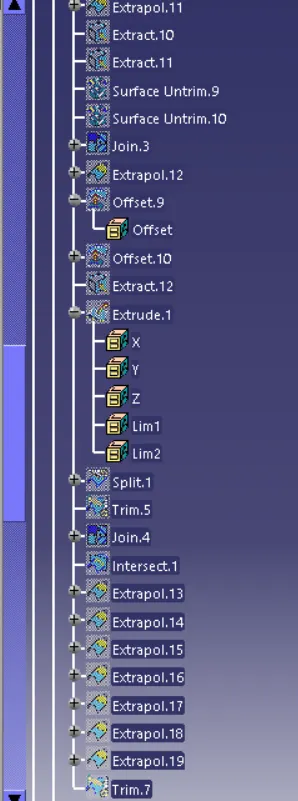
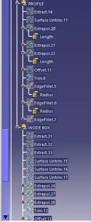
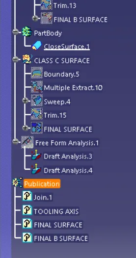
TREE STTRUCTURE