Week 8 - Challenge 2 - Switch Bezel Design
Week 8 - Challenge 2 - Switch Bezel Design
OBJECTIVE:-
The objective of the project is to design the switch bezel and to do a draft analysis for it by creating the required tooling direction with the help of Bisecting method.
INTRODUCTION:-
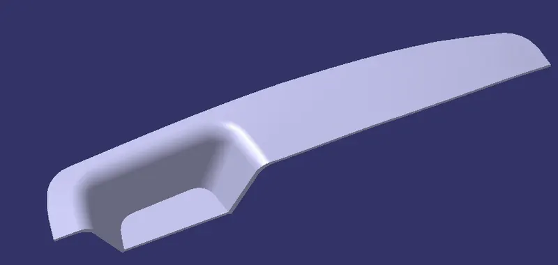
The control panel bezel is the frame part of the window switch that holds its switch covers and buttons into place. Molding is the method used to manufacture the plastic trims of an automotive by most OEMs, hence by considering the manufacturing consideration the switch bezel is designed.
DESIGN CONSIDERATION:-
- Class – A surface should be aesthetically smooth and good.
- Class – B surface should have all the supporting features like ribs.
- Parting Line should coincide with the B surface since flashing couldn’t affect the aesthetic of Class – A.
- Class – C surface should also pass the draft analysis.
DRAFT:-
Draft angle is nothing but providing some tapered portion to the part for easy removal of the component from the mold during manufacturing. This is especially done in the case of plastic component design having a complex shape. Mostly the 3-degree draft angle is provided but it can vary depending on the component which is to be designed
In our case of the Switch Bezel design, the draft angle is 3 degrees the draft analysis is done during the design of the component to check the feasibility of the product.
Before providing a draft angle we need to decide on the tooling axis also known as the molding axis considering the faces which can cause issues while manufacturing.
TOOLING AXIS:-
It is nothing but the direction in which the mold opens and closes the draft angle needed to be provided by considering this tooling axis.
We can create a tooling axis by using the bisecting method.
BISECTING METHOD:-
This method is used for the generation of the tooling axis for that purpose first we need to decide the direction of molding and then we create one dummy tooling axis for the reference to the purpose.
In this method, we select the surfaces which can create problems and take intersections in the x and y-direction. By using these curves we draw two lines and then draw a bisecting line from these two lines in the x-direction and y-direction.
If it is done in the x-direction then it is called a tooling axis clearing the x-direction and if in y then the tooling axis clears the y-direction.
After completing this we need to draw a final line bisecting these two tooling axis in the X and Y directions to get our final output.
Class A:
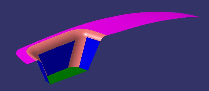
Class A Draft Analysis:
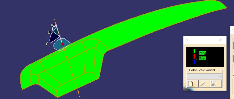
Tooling Axis:
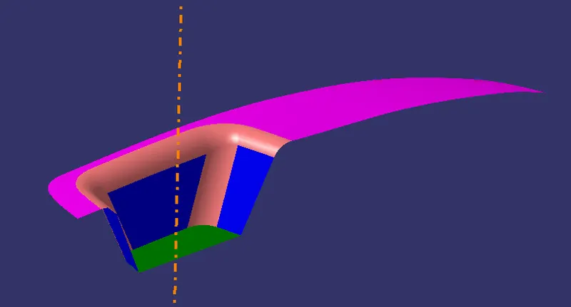
Axis Clearing all surfaces:
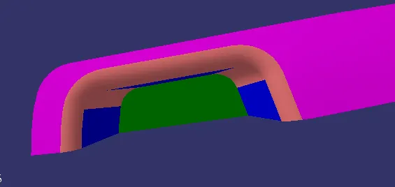
Class B:
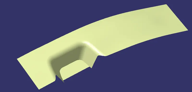
Class C:
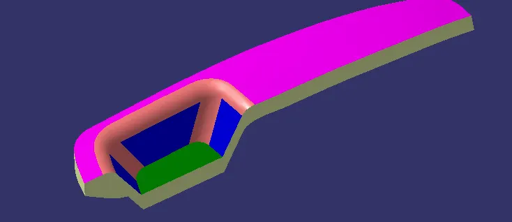
Closed Surface:
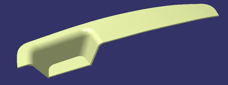
Closed Surface of Draft Analysis:
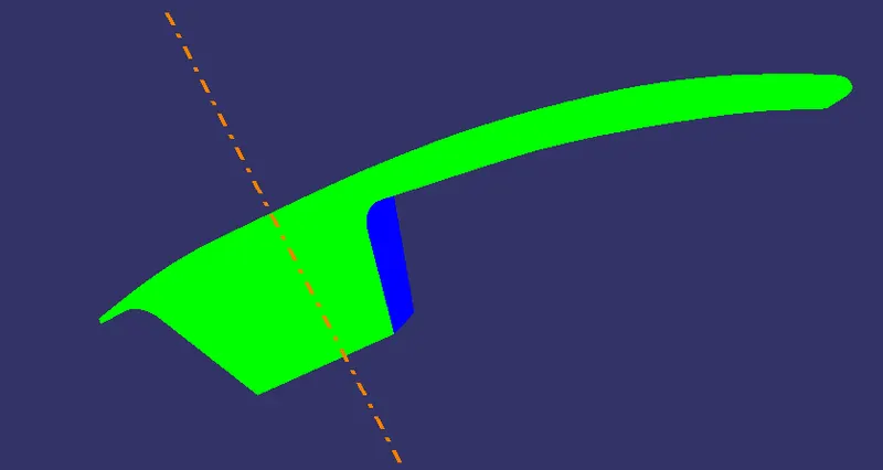
Solid Body:
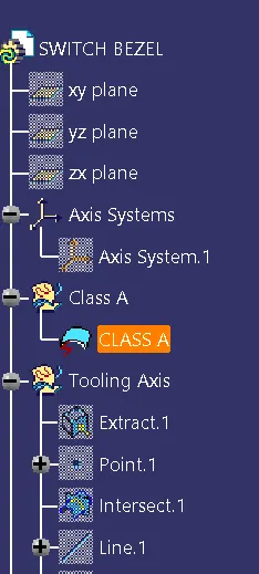
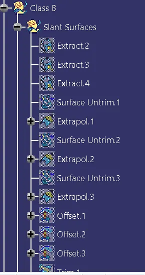
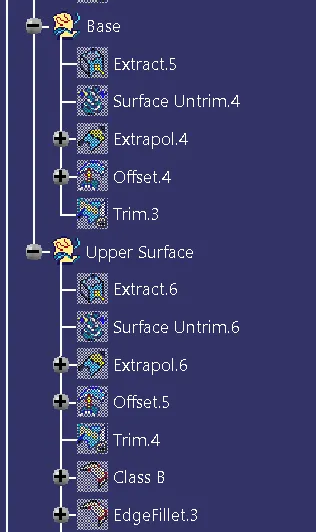
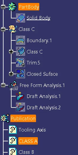
Tree: