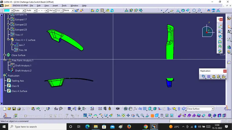
Week 8 - Challenge 2 - Switch Bezel Design
Objective :- We will Create Switch Bezel plastic Component by the help of given class A Surface after that we will do draft analysis on this model.
Steps for Tooling axis creation -:
1. First step we will extract the base surface from class A surface then we will take point on the Surface after that We insert the axis system on this point. Now we will go into the sketcher workbench where we will select the position sketch. In the position sketch we will select the reference plane like if we will take ( YZ plane then we will get tooling direction along y-axis and ZX plane then we will get tooling direction along X-axis).
2. Second step we will take intersection of a class A with XZ plane then we will draw a line on intersection line in class A. Since We do not have any other surface to draw the line thats why we will draw a line and this line will passing through projection point with making 3 degree angle with reference plane.
3. Third step we will use bisecting method to get actual tooling axis.
the axis system on this point. Now we will go into the sketcher workbench where we will select the position sketch. In the position sketch we will select the reference plane like if we will take ( YZ plane then we will get tooling direction along y-axis and ZX plane then we will get tooling direction along X-axis).
2. Second step we will take intersection of a class A with XZ plane then we will draw a line on intersection line in class A. Since We do not have any other surface to draw the line thats why we will draw a line and this line will passing through projection point with making 3 degree angle with reference plane.
3. Third step we will use bisecting method to get actual tooling axis.
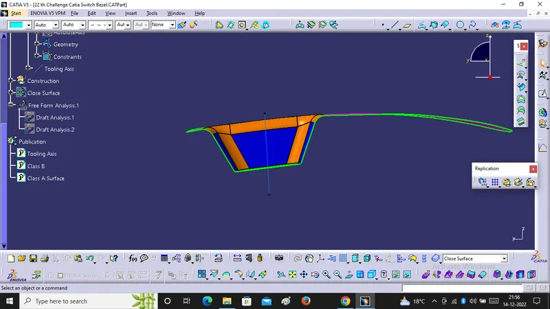
4. Now we will perform the Draft Analysis on Class A surface. In draft analysis we have to follow some step, click on the Compass Icon, drag it to the tooling axis and align it with the tooling axis. After that we have to click in option of customize view parameter mode and select the material option and then we will click on the Base Bracket Surface.
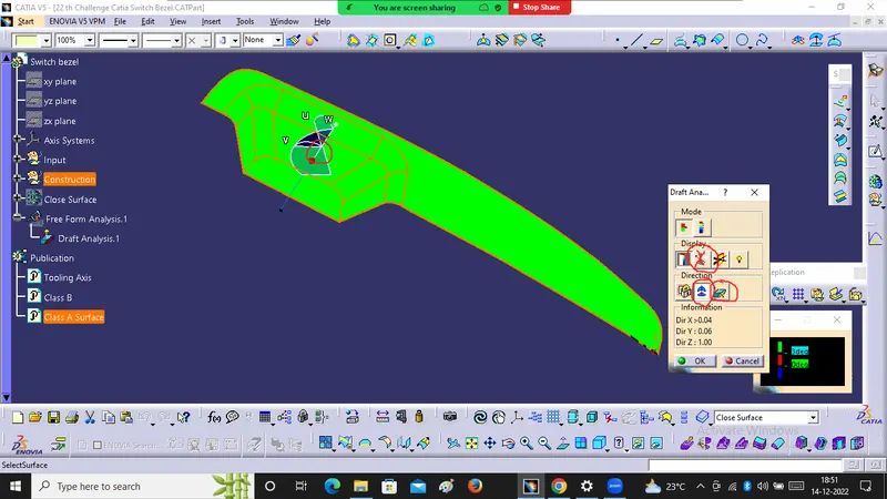
In the above image we can see that surface is green colour has draft angle greater than 2 degree and which is most required for Tooling feasibility.
5. Now we will check the degree of the surface for that we will go to the features draft analysis Toolbar and click the analysis under the running point option after that we move the mouse cursor on the surface it gonna shows how much degree is their for that specific point. so if the degrees are ok then it will be ready for design.
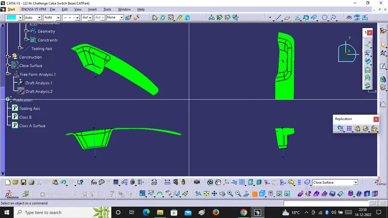
Screenshots of the draft analysis in various orientation ( Isometric, Front, Side and Top View)
For B Surface Creation :-
1. We have to extract the top surface from class A Surface and untrim the surface.
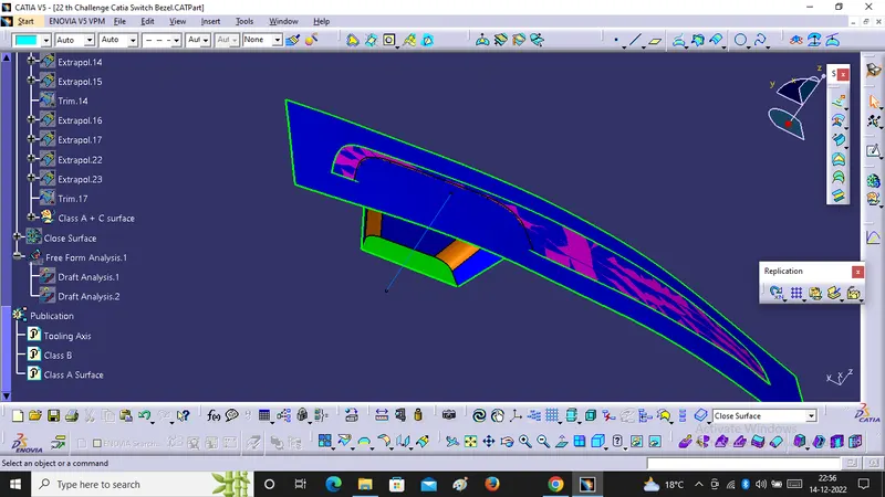
2. We will extract the bezel from class A surface and untrim the Surfaces.
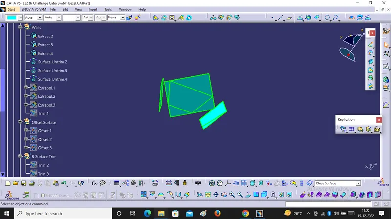
3. We will extrapolate the Surfaces . Use continuity as Curvature and propgation mode as Point Continuity.
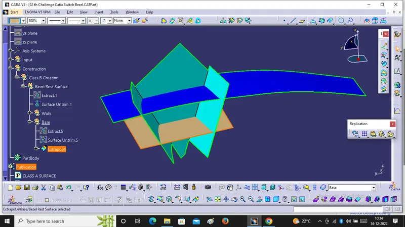
4. We will trim the surface and offset it for 3mm.
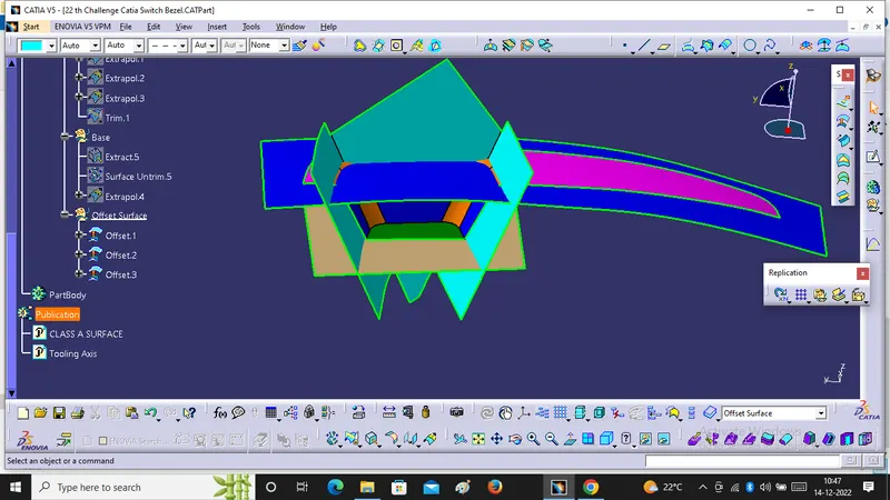
5. After that we will do final trim and applying proper fillets value, we will get B surface. Measuring the proper fillet from A surface.
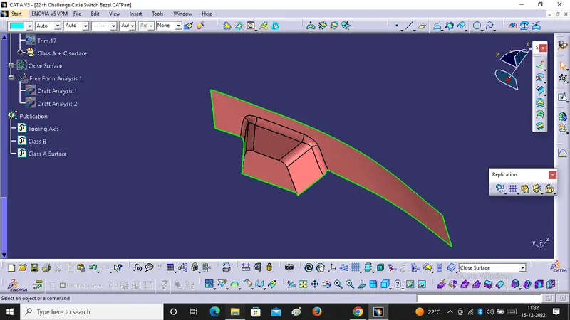
For C Surface Creation:-
1. We will extract outer boundary of the Class A surface by the help of using multiple extract Command. After that we will go the curve Smoothing option and Joined the outer boundary.
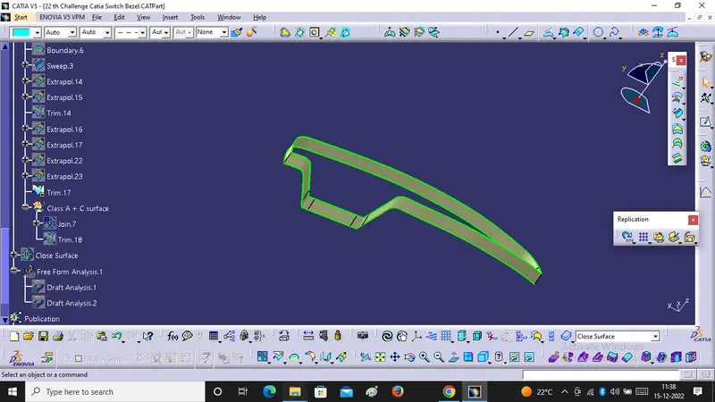
2. We will use sweep command to create C Surface.
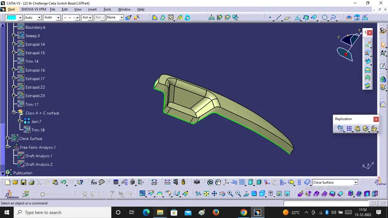
3. After that we will extrapolate the C Surface and trim the edges to get final Switch Bezel Model.
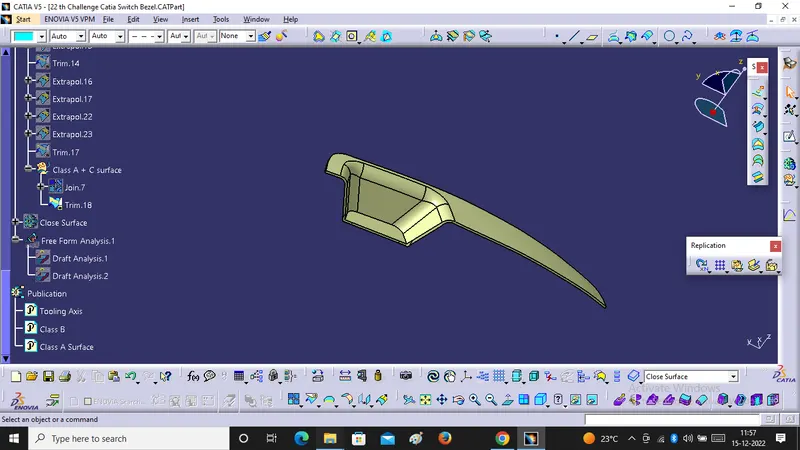
To get Close Body:-
We have to go into the part design workbench as well as defined in the part body and select the close Surface Command then we get Solid Body.
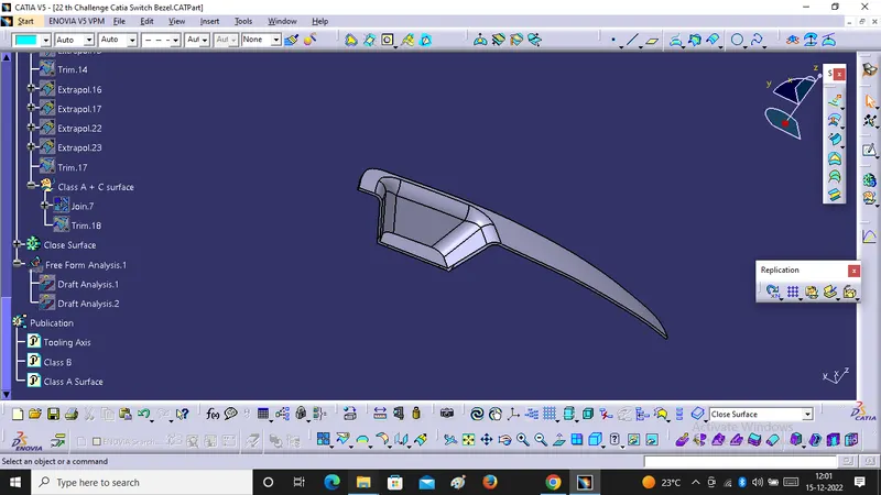
After that we have to draft analsis for close surface .