Week 8 - Challenge 2 - Switch Bezel Design
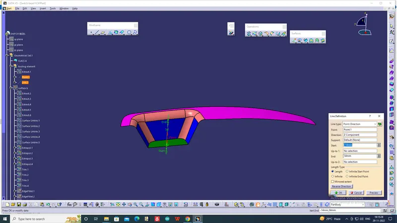
Tooling axis: The direction in which the mold or core and cavity opens is the tooling axis
Tooling Axis creation:
Using the tooling axis created along x and y-axis, these tooling axes are used for creation of tooling axis by bisecting method where the two lines and point will be selected as inputs.
Draft Analysis:
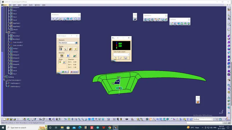
Draft analysis is done after determining the tooling axis, draft analysis is used to check whether the minimum draft (3 degrees) is maintained or not.
Compass is used to define the draft direction.
If the minimum draft 3 degree is provided the whole component changes in to green colour.
SURFACE A
- First, the given styling surface is checked for any irregularities and if found any then it is corrected by using Trim, Extrapolate, Split and Join commands.
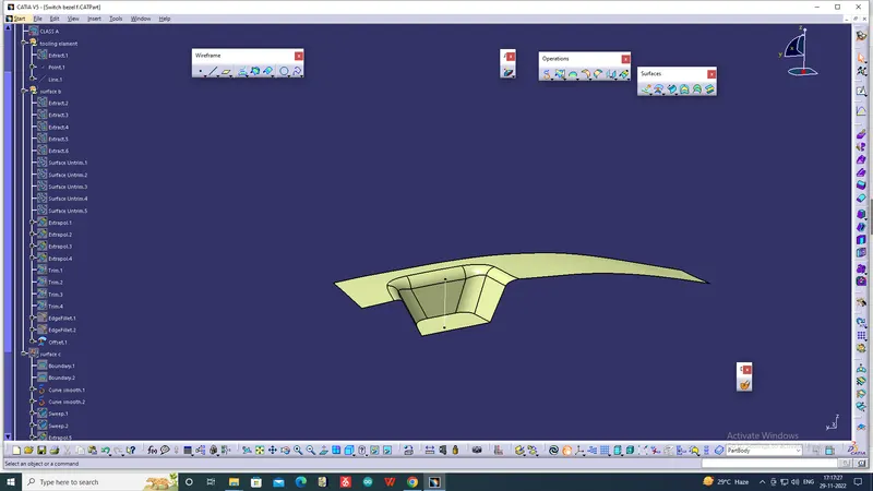
- The below image shows that the Class – A surface is clean and no irregularities present, so let's move on to the next step.
- SURFACE B
Class-B surface is created by extracting each walls and un-trimming and extrapolating the walls to obtain the shape by trimming the excess surfaces and offsetting it to certain distance based on the thickness of the model and giving fillets wherever it is necessary. The offset surface will be the B-Surface.
CREATION OF SURFACE B
- For creating the class-B surface the required surface except the offset surface have been extracted and then untrimmed all the surface.
- Then all the surfaces have been extrapolated to get intersections between them.
- Since the thickness of the Switch bezel is 2.5mm the B-Surface was offset to 2.5 mm and the required trim operations must be carried out.
- Finally, the required corners have been filleted to 12.5mm (15mm-2.5mm). [ 15mm - fillet value of the A-surface, 2.5mm – Thickness of th]
C-Surface:
The surface created using the sweep option by sweeping the boundaries of A-surface along the tooling axis to connect from A to B-surface is called C-Surface.
CRETION OF SURFACE C
-
- The required outer edges of the A-Surface were extracted using Multiple Extract. Then for avoiding the patches the curve is smoothened using the Curve Smooth option.
- Then by using the sweep command the surface was created with the following feature controls,
- Profile type – Line
- Subtype – With Draft Direction
- Guide Curve – Smooth Curve
- Draft Direction – Tooling Axis
- Draft Computation Mode – Square
- Angle – 3 Degree
- Angle Sector – Positive Downward (1)
- Length – 20mm
- Then by using extrapolate command the edges were intersected between the surface corners which eases the trimming operation.
- Now the required portion of the C – surface were trimmed out.
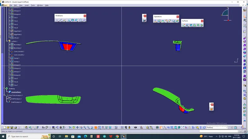
FINALY SOLID BODY DRAFT ANALYSIS
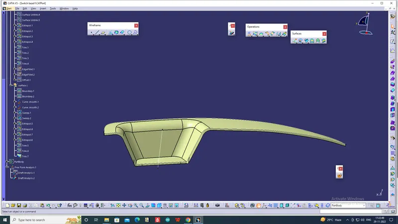
Finally the Class – A, B&C surfaces with the Tooling Direction have been Published and the Switch Bezel is moved on to the designing of the next operation – the creation of B-side features.