Week 8 - Challenge 2 - Switch Bezel Design
OBJECTIVE
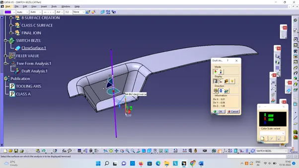
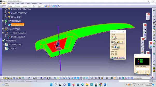
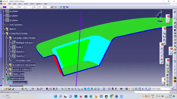
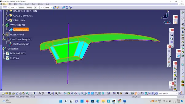
The objective of the project is to design the switch bezel and to do a draft analysis for it by creating the required tooling direction with the help of Bisecting method.
INTRODUCTION
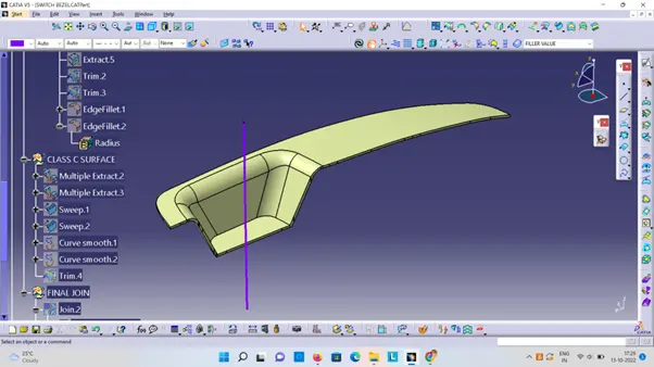
The control panel bezel is the frame part of the window switch that holds its switch covers and buttons into place.
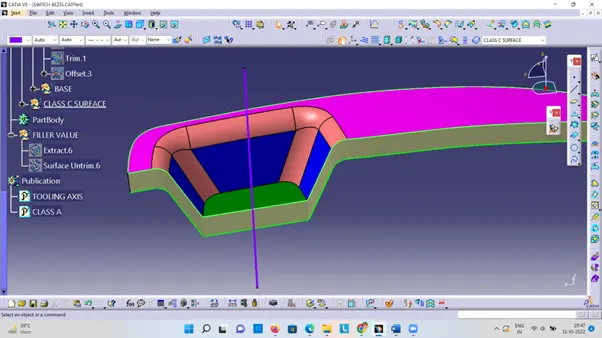
Class – A surface should be aesthetically smooth and good.
Class – B surface should have all the supporting features like ribs.
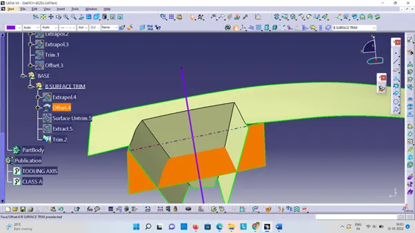
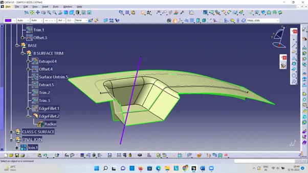
Parting Line should coincide with the B surface since flashing couldn’t affect the aesthetic of Class – A.
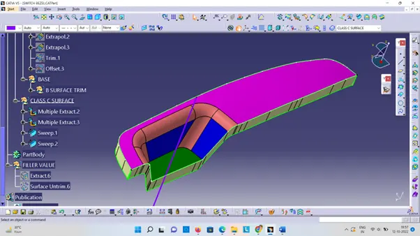
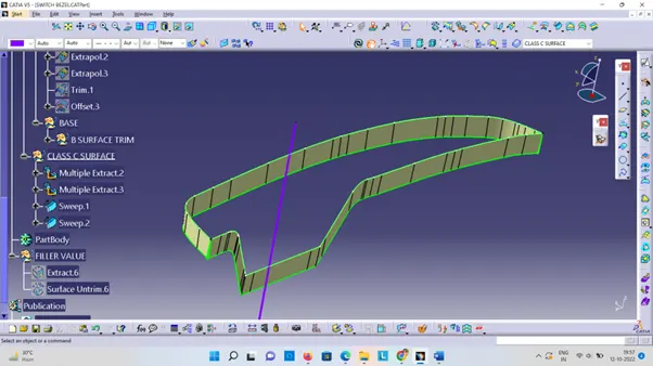
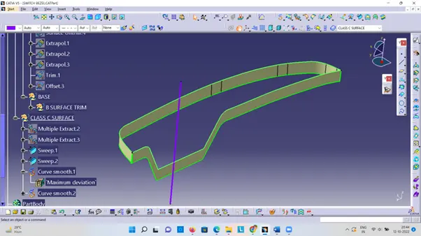
Class – C surface should also pass the draft analysis.
PROCEDURE FOR CREATING THE SWITCH BEZEL
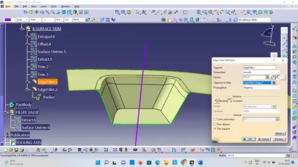
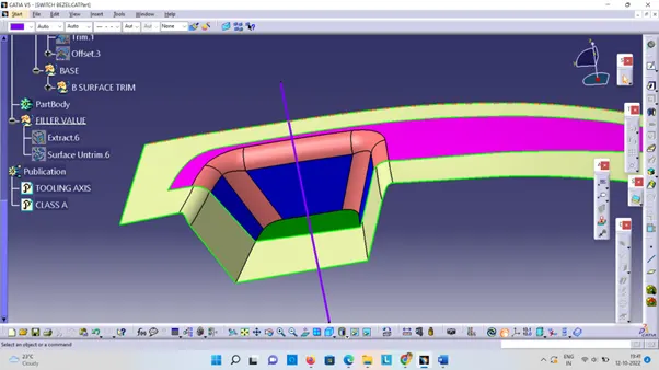
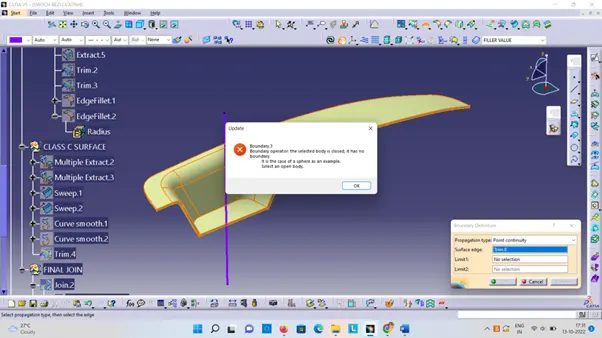
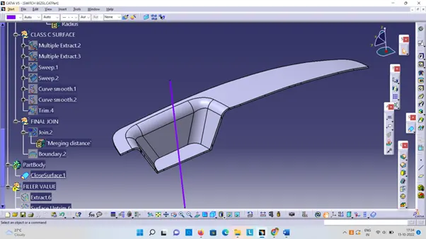
The given styling surface is checked for any irregularities and if found any then it is corrected by using Trim, Extrapolate, Split and Join commands.
SETTING OF TOOLING DIRECTION
Considering the Ejection from the cavity of the mould after manufacturing the interior trim (switch bezel) must have the nominal 3-degree draft angle.
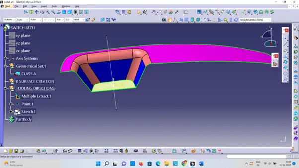
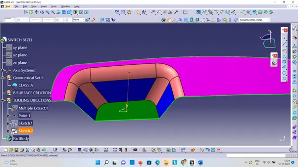
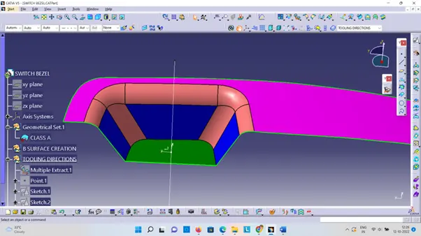
Hence the tooling direction is created.
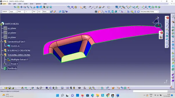
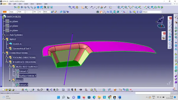
The base surface of the class – A was extracted.
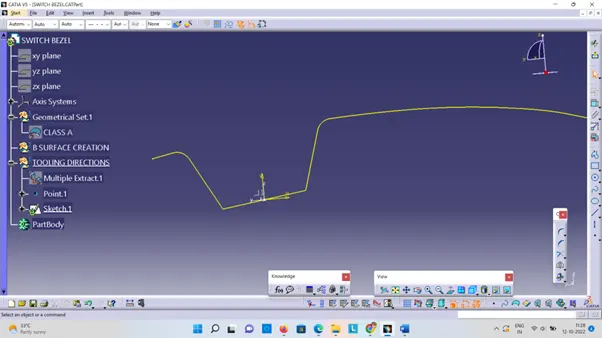
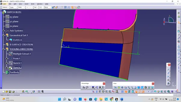
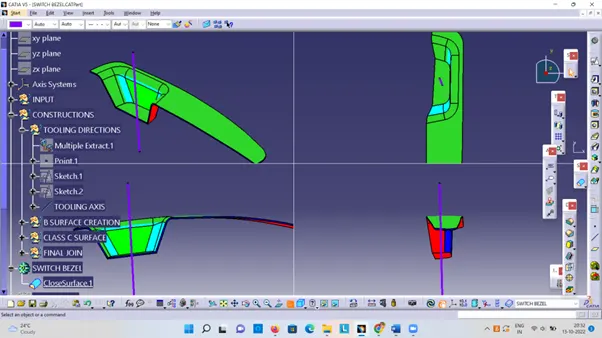
Creating Sketch1 & sketch 2.
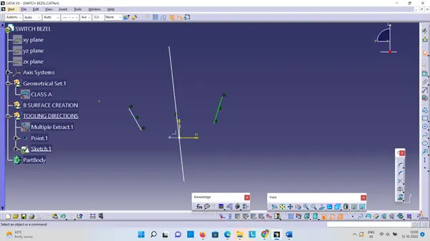
Then, using project intersection along yz plane is created and the two inclined lines were drawn inside the positioned sketch.
Then bisecting lines were drawn..
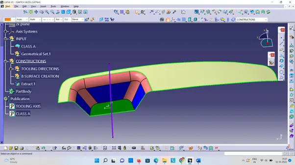
Now the same procedure is done along the xz plane is used to extrude a line along the z-direction.With Sketch1 & sketch 2 publish the Tooling Axis.