Week 8 - Challenge 2 - Switch Bezel Design
AIM
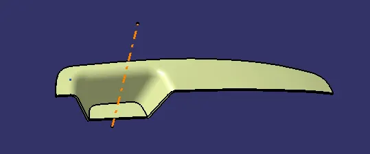
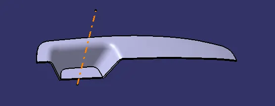
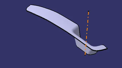
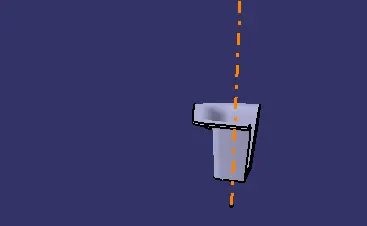
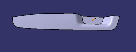
Create the Switch Bezel Plastic component through the given Class-A surface.Create the tooling axis for the given Class-A Surface meeting the requirements of the draft angle and at the end perform the Draft analysis on the model.
REPORT
CLASS A SURFACE
In automotive design , a class A surface is any of a set of free form surface of high efficiency and quality. Although, strictly, it is nothing more than saying the surfaces have curvature and tangency alignment – to ideal aesthetical reflection quality, many people interpret class A surfaces to have G2 (or even G3) curvature continuity to one another. It gives the aesthetic of the component which is created by the styling team and gives to the part design engineer to create the part with all engineering aspects.
CLASS B SURFACE
Class-B surface means the thickness of a part it is not visible and is inside part. In other words, the Class-B surface is a surface below a certain thickness from the class-A surface. This is the surface that contains engineering aspects of a model.The Class B finish is a quality finish with only minimal imperfections. A Class B finish is the most common finish for exterior surfaces. It is normally specified on surfaces such as external covers, panels, and parts that are fairly prominent.
The surface that joins class-A and class-B surfaces are class-C surfaces. Class C is often specified for interior surfaces not readily visible, surfaces that will be covered by another part when assembledThe Class C finish allows more imperfections than Class A or B. Class C is often specified for interior surfaces not readily visible, surfaces that will be covered by another part when assembled, or surfaces which the Customer feels do not need to meet a high cosmetic finish.
DRAFT ANGLE
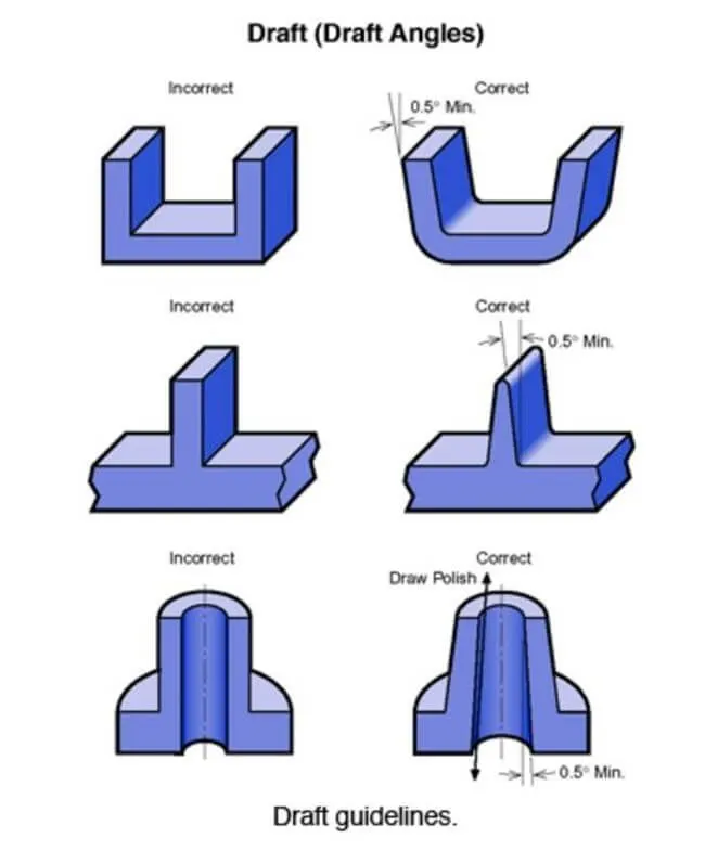
When developing parts for plastic injection molding, applying a draft (or a taper) to the faces of the part is critical to improving the moldability of your part. Without it, parts run the risk of poor cosmetic finishes and may bend, break, or warp due to molding stresses caused by plastic cooling. Equally important, an absence of draft may prevent parts from ejecting from the mold, damaging not only the parts but possibly the mold itself—a costly and time-consuming detour.
STEPS
CLASS A SURFACE
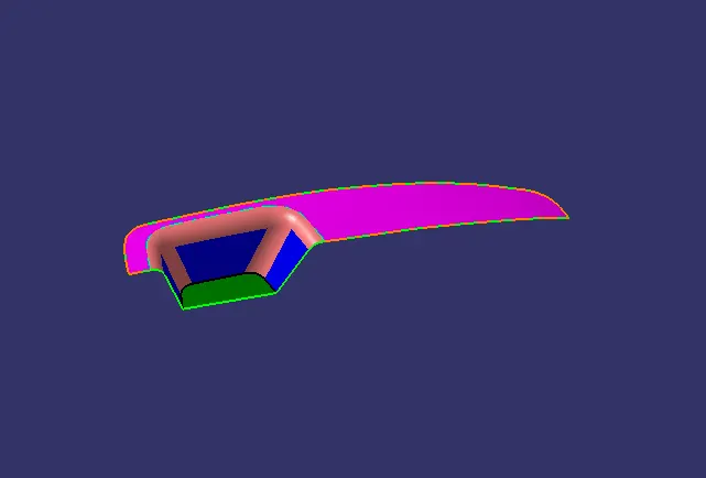
We have been given the Class-A surface and the first thing to do is to make sure that the given surface has no gap in between them. We can check it visually and also with help of Join or boundary commands.
The given surface has only one boundary . So, there are no other gaps found.
TOOLING AXIS
The direction in which the mold or core and cavity opens is the tooling axis.
TOOLING AXIS USING BISECTING METHOD
Tooling axis for the part is created by using the bisectiong method .In order to check whether the part is toolable in the direction,the class A surface is analysed and the walls which are doubtful of clearing the 3 degree draft angle to the dummy tooling axis is identified.
In this class A surface there is only three walls intersection line is created on these three walls by using the sketch tool
point is created on the extraced face of the bottom wall
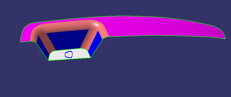
An axis system is created on the point for sketching
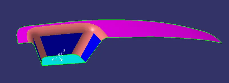
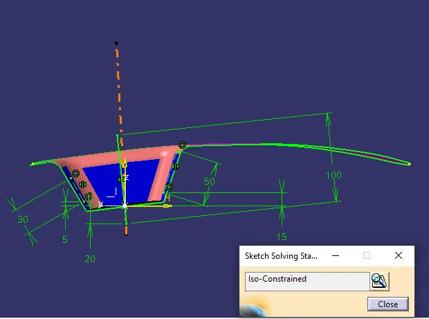
a sketch is created to obtain the intersecton
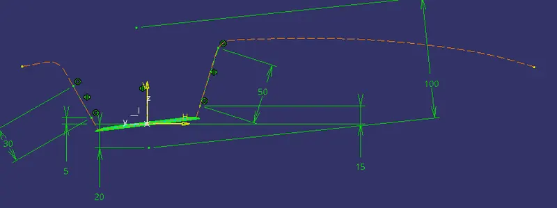
the lines are drawn in the intersection of walls
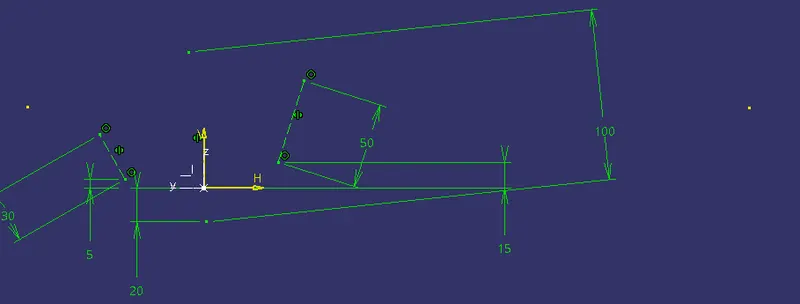
a bisecting line is created for the two lines

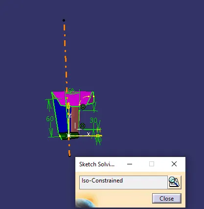
for the third single wall intersection is created using new sketch
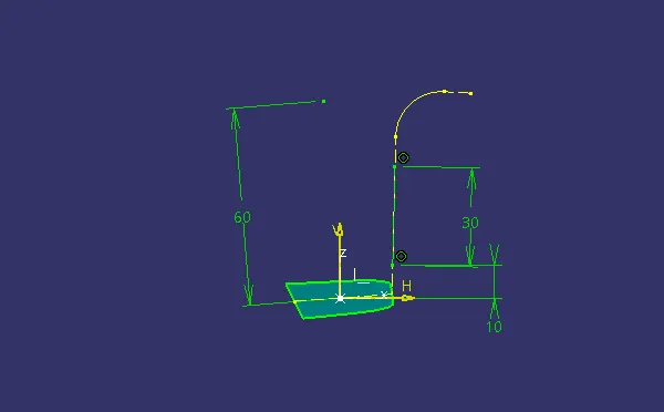
line is drawn in the intersection of wall
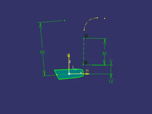
the minimum draft angle is 3 degree a line is drawn at 3 degree on the point to the line on the wall . it is increased to 6 degree to et more clearence.
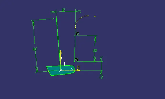
the bisecting line is created for the line on the wall and line at 6 degree to it.
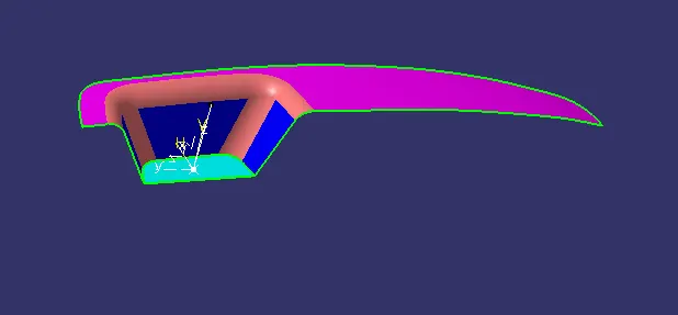
the tooling axis is created by bisecting the two lines ( bisecting line on first sketch and second sketch)
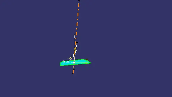
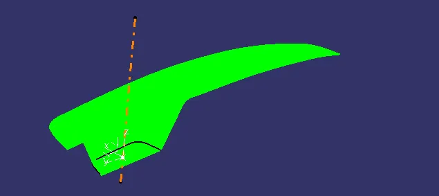
TOOLING AXIS is created
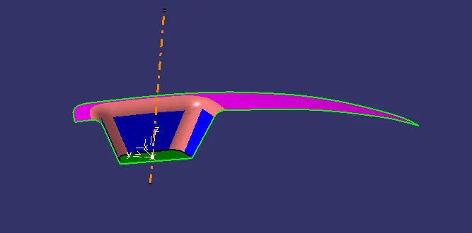
sketch soling status of two sketch
DRAFT ANALYSIS OF CLASS A SURFACE
Change the view to material mode for draft anlysis
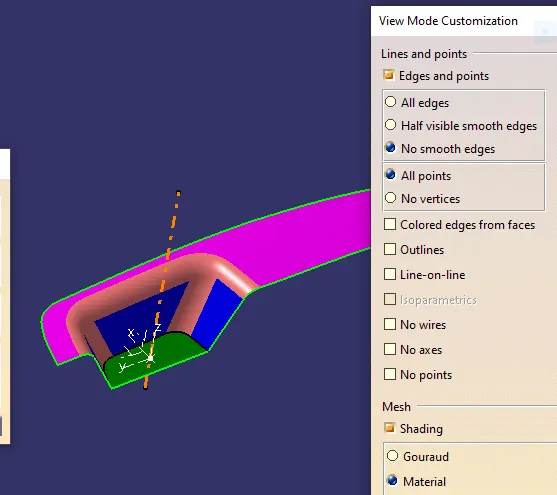
draft analysis is done using featured draft analysis tool
Use the compass fucnction to aling the compass to the tooling direction and lock the direction using lock function in the draft analysis tool bar
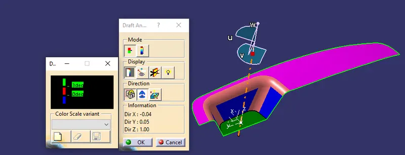
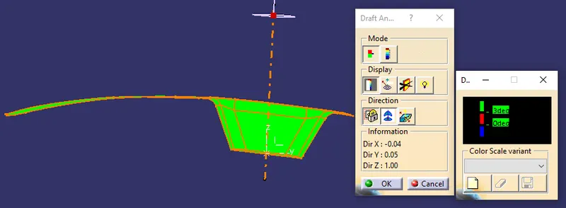
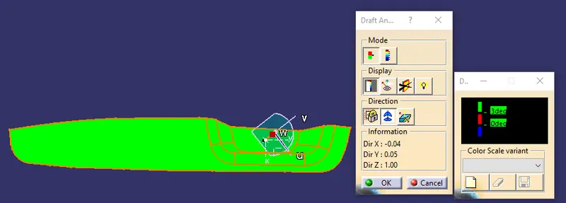
the surface is showing green colour so that the surface clears the minimum draft angle of 3 degree
By using the analyses under the running pointwe can check draft angle on the individual faces. It shows how much draft on specific points when we move the cursor point.
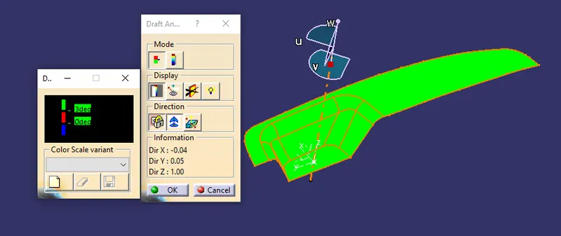
Green colour - above 3 degree positive draft
Red colour -between 3 and 0
blue colour- below 0 degree
CLASS B SURFACE
B surface gives thickness to the component. all the engineering features are made in the B surface
WALLS
extracted the surface
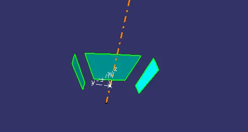
untrim the surface
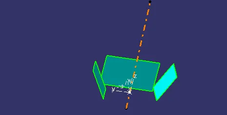
Extrapolate the surface
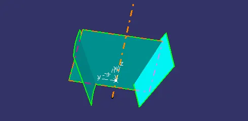
Trim the surface
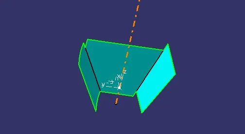
offset to the thickness
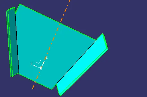
WALLS is created
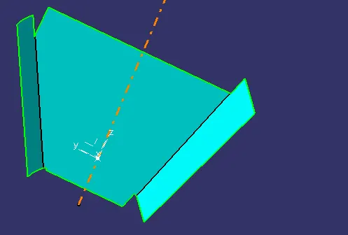
BEZEL REST SURFACE
extracted the surface
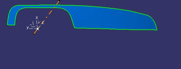
untrim the surface
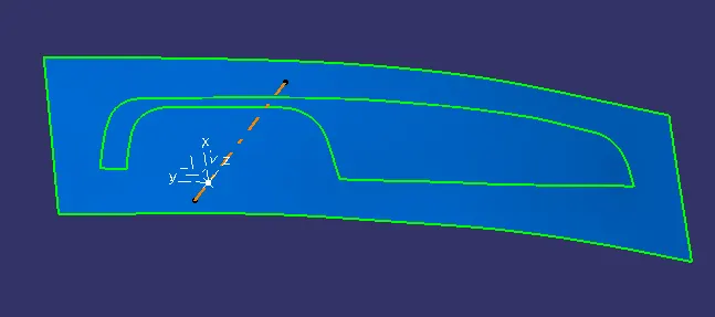
offset to the thickness
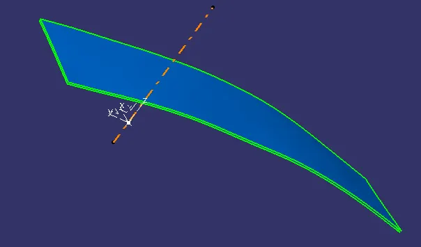
BEZEL REST SURFACE is created
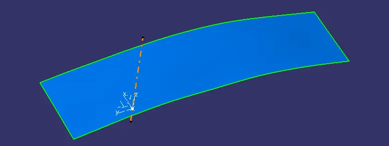
BASE
extracted the surface
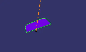
untrim the surface
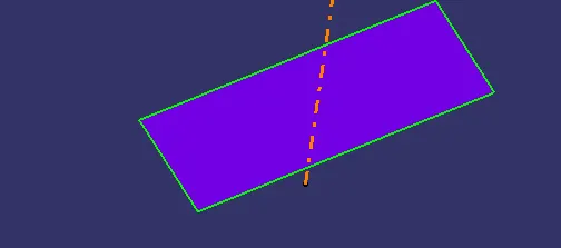
offset to the thickness and BASE is created
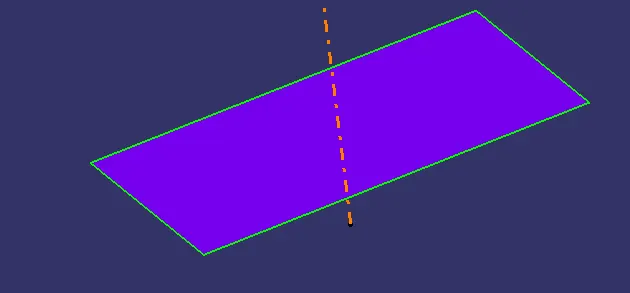
B SURFACE TRIM
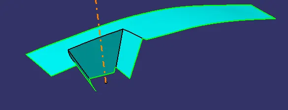
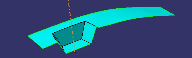
Fillet is provided and B SURFACE is created
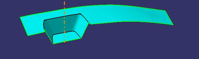
CLASS C SURFACE
The first step is to create the boundary of the CLASS-A surface by extract command.
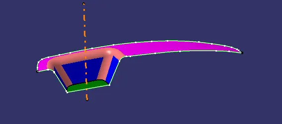
Then using the sweep command create the CLASS-C surface
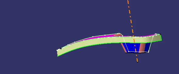
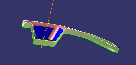
the curve is smoothened using smooth curve command and the two two walls joint are extrapolated andtrimmed together to form CLASS C SURFACE
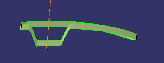
CLOSED SURFACE
CLASS A B & C trimmed to form CLOSED SURFACE
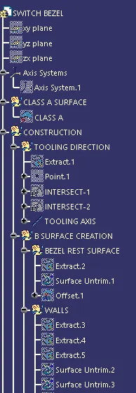
TREE STRUCTURE
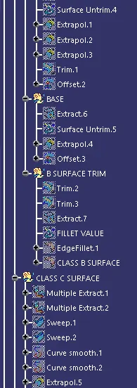
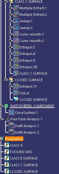
PART BODY
Close Surface feature used to make a solid body from the surface.
DRAFT ANALYSIS OF COMPONENT
draft analysis is done using featured draft analysis tool
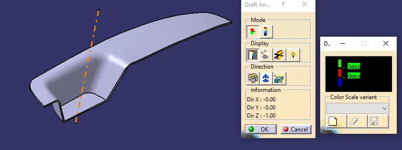
Use the compass fucnction to aling the compass to the tooling direction and lock the direction using lock function in the draft analysis tool bar
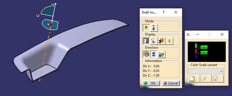
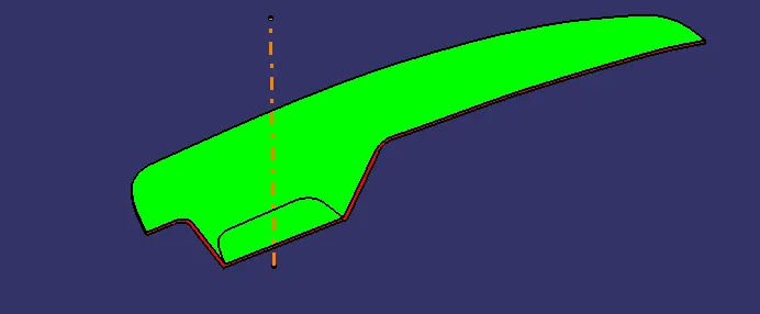
the surface is showing green colour clears the minimum draft angle of 3 degree
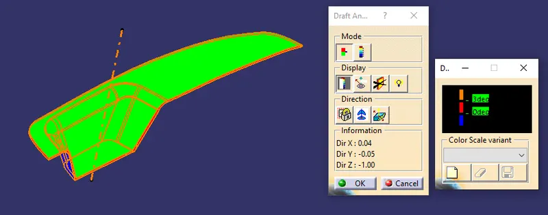
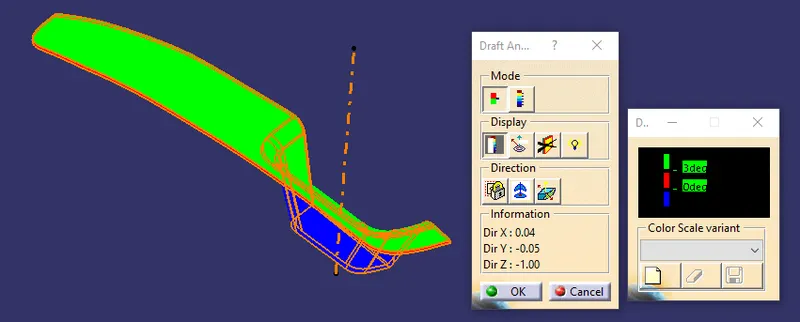
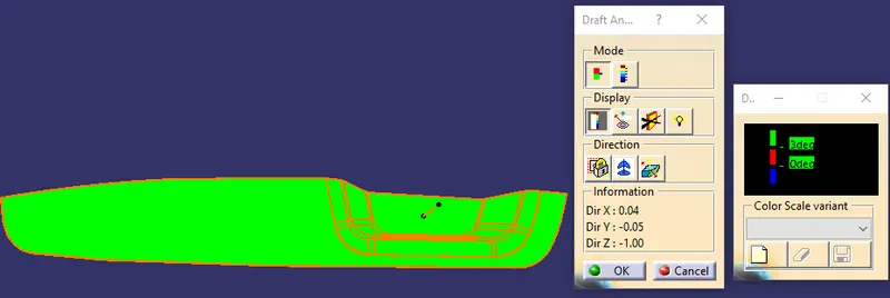
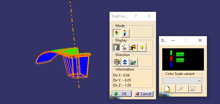
By using the analyses under the running pointwe can check draft angle on the individual faces. It shows how much draft on specific points when we move the cursor point.
Green colour - above 3 degree positive draft
Red colour -between 3 and 0
Blue colour- below 0 degree
CONCLUSION
- Created the Base Bracket Plastic component through the given Class-A surface.
- the tooling axis for the given Class-A Surface is created which meeting the requirements of the draft angle
- Draft analysis is done on the CLASS A surface
- Draft analysis is done on the model.
- Using the Close Surface feature solid body is created from the surface
- Publications: Tooling Axis Class A, B, and C surface and solid body