Week 8 - Challenge 2 - Switch Bezel Design
- Aim: Create the Switch Bezel Plastic component through the given Class-A surface.
- Objectives:
- To create class B & C surface for the given component.
- To form the tooling axis and capture the surface properly.
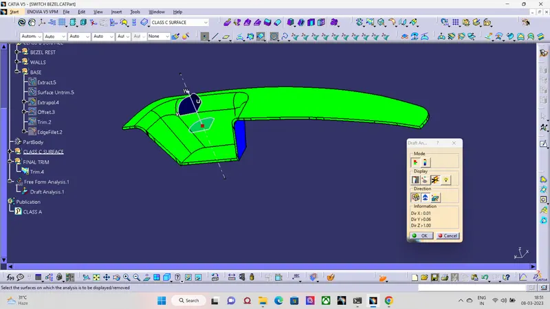
- To check the feasibility of the component with a draft of 3 degrees.
- Method:
- In order to obtain the proper draft analysis tooling axis is required and the following steps show how it is done.
- As this component has 1 hole from where the tooling axis can be generated, however it does not have proper 4 walls to generate it. In this case, an approximation is made in order to obtain the tooling axis.
- First by using the two side walls a dummy axis is made. As it is known that the draft angle is 3 degrees, the second axis is taken as a 3 degrees to the given wall and using these two axis the tooling axis is made. 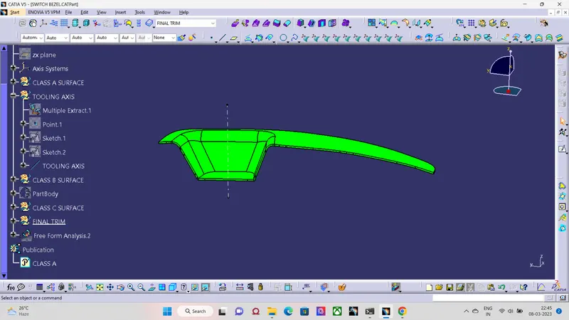 Once all the adjacent surfaces are taken, they are trimmed and form into the bezel surface.
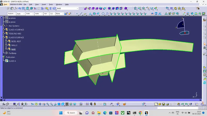 As per the requirement, the fillets are given. In order to given the fillets it is not exactly equal to class A. Along with the fillet radius, part thickness has to be added.
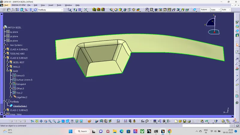 To Capture class C surface it is necessary to sweep it to the required length. However for this as the border formed is having number of small sections the border curve can be smoothened and then swept or else done in parts.
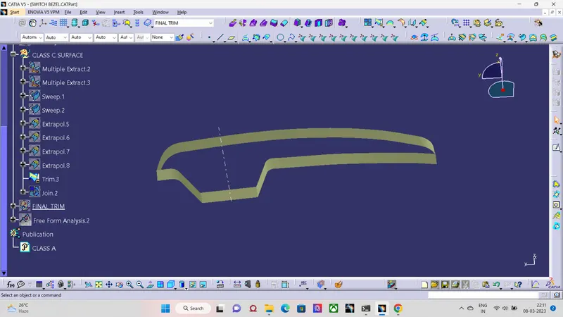 After forming the class b & C all the three surfaces can be trimmed and check for any discontinuity.
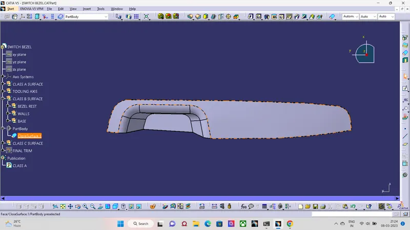
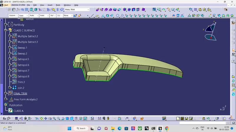 After trimming, this is how the surface will look like.
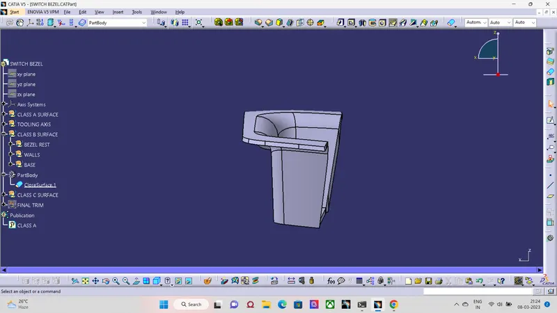
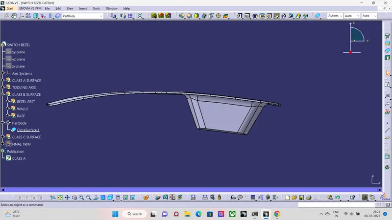
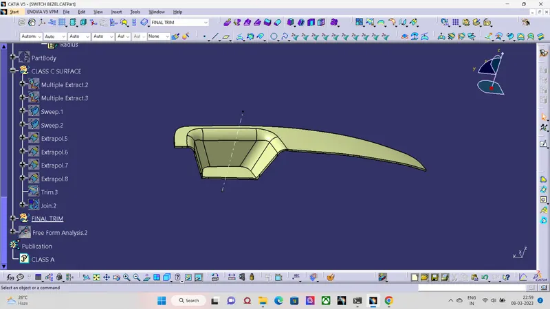 Solid formed after the class A,B & C surface.
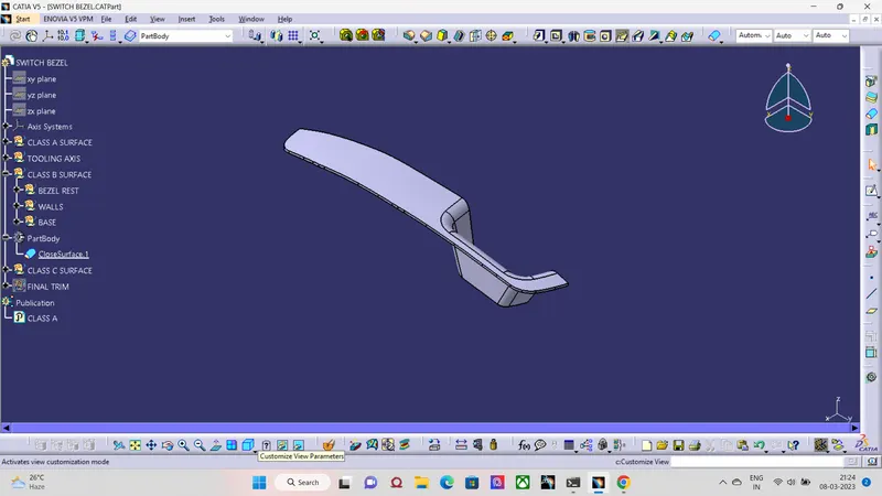 After increasing the angle it can be seen that there is no draft failure and now the component is feasible and can be manufactured.