Week 8 - Challenge 2 - Switch Bezel Design
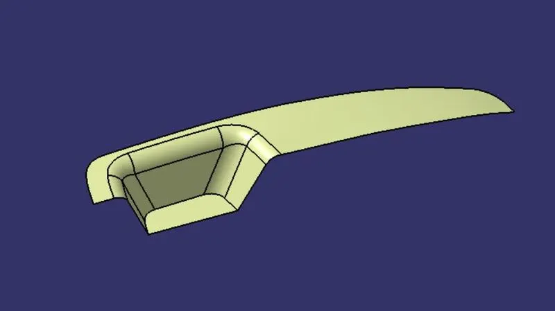
Aim :- To create the Switch Bezel Plastic component through the given Class-A surface. To begin with, the tooling axis for the given Class-A Surface should be created meeting the requirements of the draft angle and at the end perform the Draft analysis on the model.
Given Data :-
Thickness of the component = 2.5 mm
Class A Surface -
By using Boundary Command ,I have check given Class A surface Contunity.
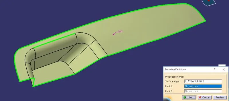
I found there is one discontunity in Class A surface .
Then by using Join command I have given merging distance as 0.003 mm for rectifying this issue.
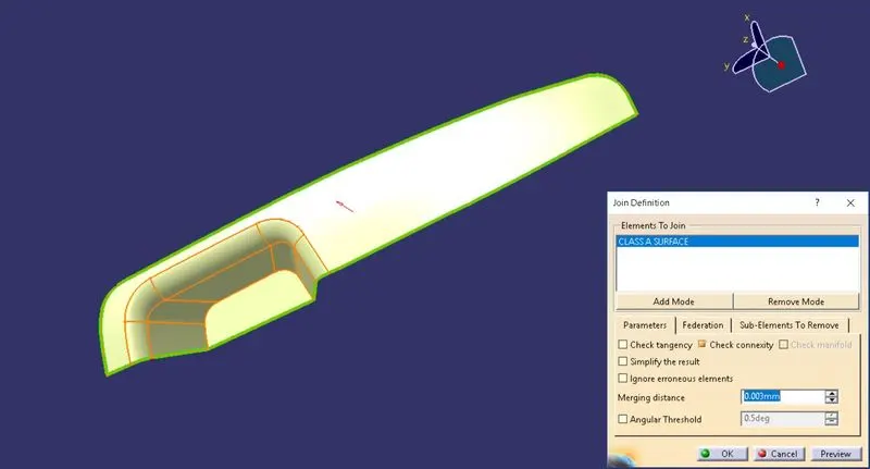
Creation of Tooling Axis -
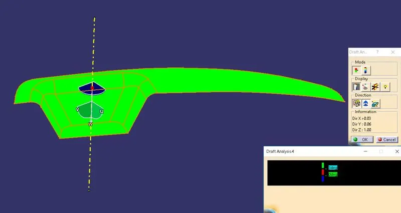
From given Class A surface I found that Z-direction is the best possible tooling direction. Then I have check this direction is clearing all surfaces along X and Y-direction or not.
Creation of Y-Direction line-
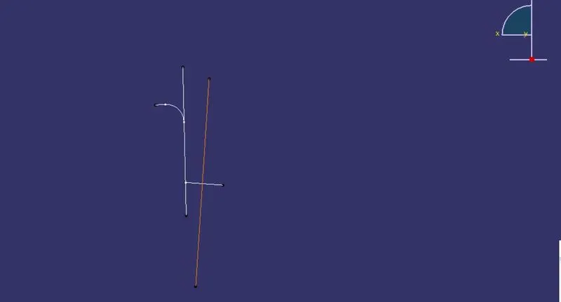
By using intersection I have intersect Class A surface along Y-direction. Then make Y direction Clearing line.
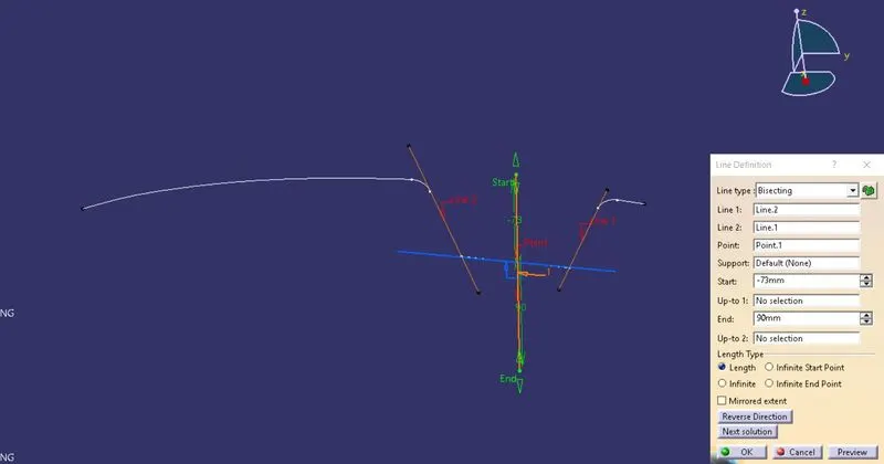
Creation of X-Direction line-
Same as Y-Direction line I have drawn X-Direction line.
Main Tooling Axis -
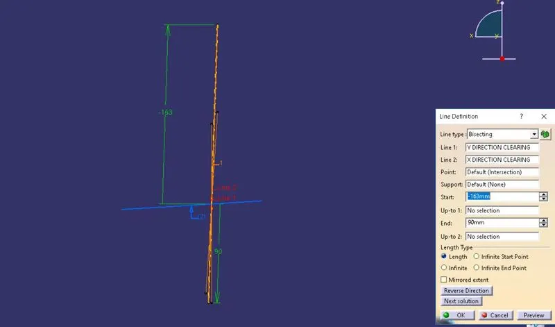
By using Bisecting Line method I have created main tooling axis.
Draft Analysis on Class A Surface -
Creation of Class B Surface -
All the steps for creating Class B Surface are shown bleow.
Step 1 - Extraction of Surfaces from Class A.
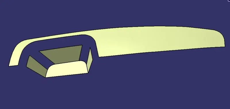
Step 2 - Offseting extracted surfaces.
I have offset all surfaces by 2.5mm as given thickness of componenet.
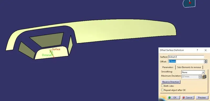
Step 3 - Untrim of Offseted Surfaces.
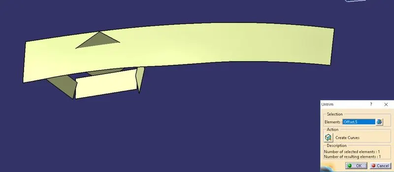
Step 4- Extrapolating of untrimed surfaces.
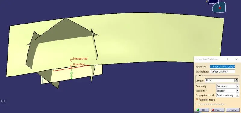
Step 5- Trimming of extrapolated surfaces.
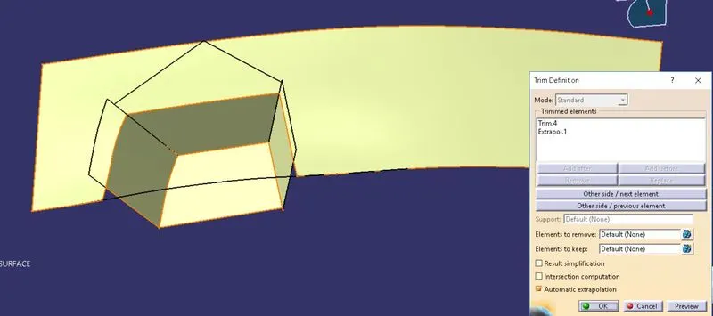
Step 6- Give edge fillet.
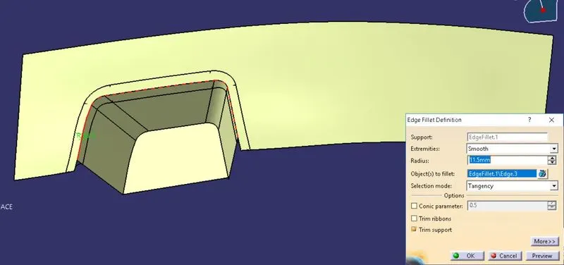
Then we get final Class B surface.
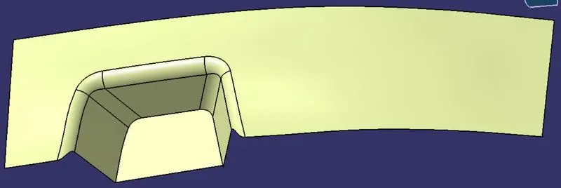
Creation of Class C surface -
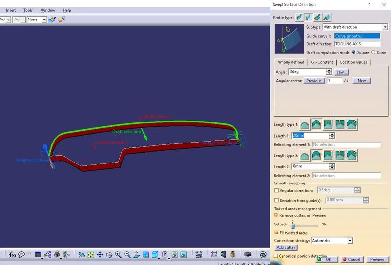
For creating class c surface I have use outer boundary of class A surface and by using sweep with draft directrion I have create class C surface.
Then I extrpolated end edges of this surface.
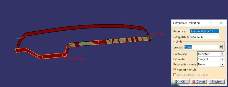
After Trim operation we get final class C surface.
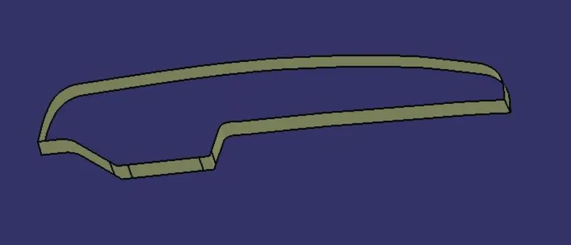
Final Surface Body of Component -
By using join and Trim operation we get final surface body from Class A ,B and C surfaces.
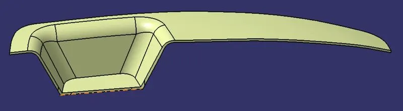
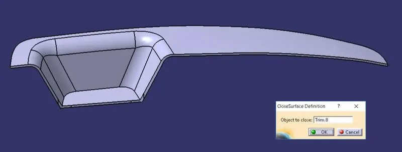
Making Solid Body from Surface Body -
By using close surface we get final solid Switch Bezel Plastic component.
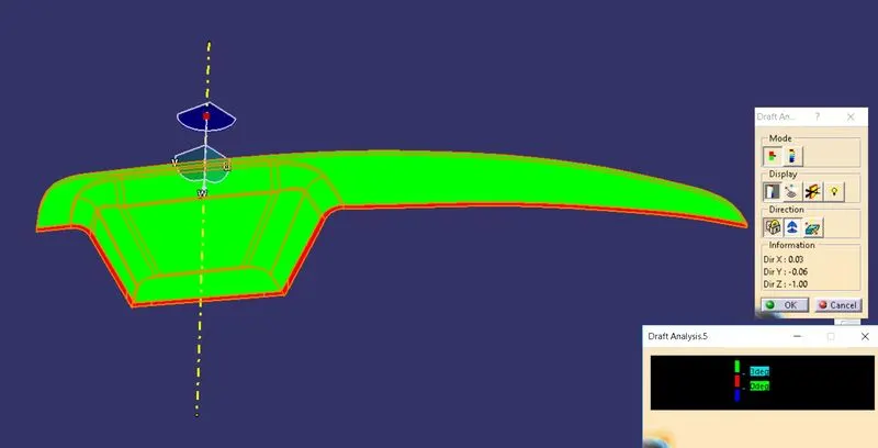
Draft Analysis on Solid Body -
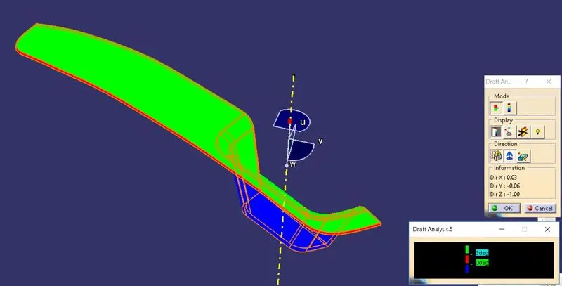
Isometric View -
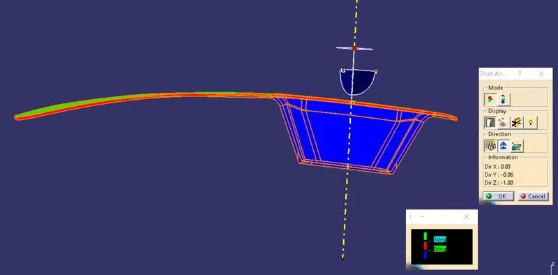
Front View -
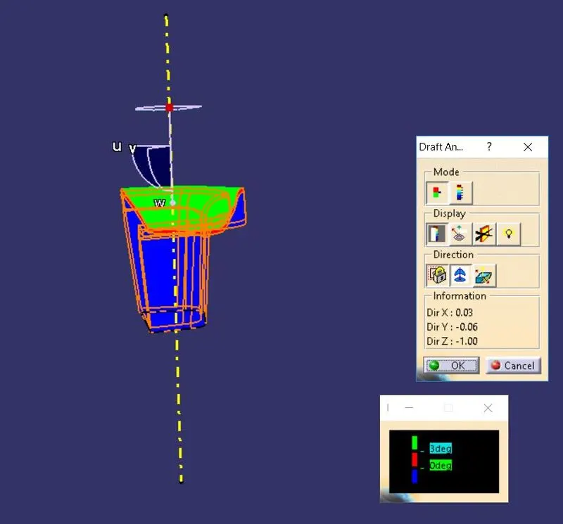
Side View -
Top View -
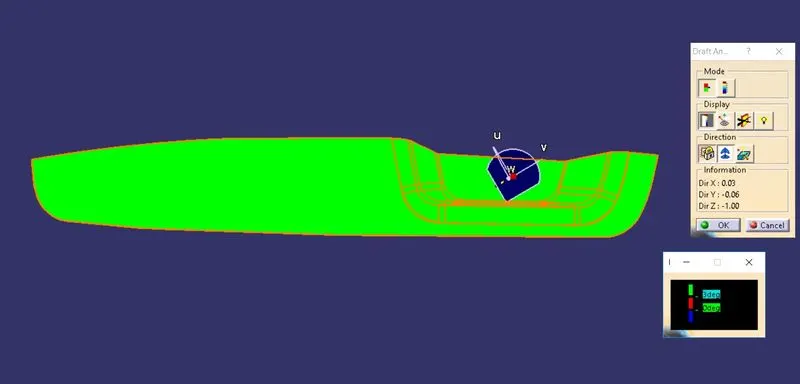
From above draft analysis we found that upar side of component is green in colour beacause all this faces are at an angle more than 3 degree to tooling axis. While Side surfaces are red in colour because this surfaces drafted at an angle 3 degree and bottom side is blue in colour because there is negative draft.