Week 8 - Challenge 2 - Base Bracket Design
Base Bracket Design:
The aim of this challenge is to create a Base Bracket based on the input A-surface given.The desired result is to create B-surface and C-surface based on the tooling axis created and using all A,B and C surfaces to
create a solid body of Bass Bracket.
The other inputs considered for this designs are
Thickness of component : = 2.50 mm
Draft angle = 3 Degree.
A-surface given as IGS file.
Creation of Tooling Axis:
The tooling axis is the axis in which core and cavity of a mold move apart and the component is ejected. In this case, the component is checked in X,Y and Z directions.
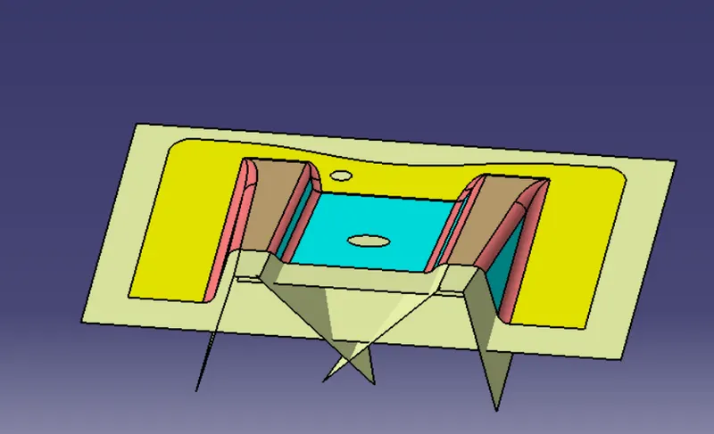
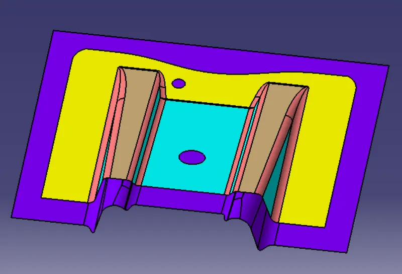
In X and Y directions , there are features that needs seperate tooling axis.(See Image 1,2,3)
It is clear from below image 3 that tooling axis in Z direction, al the features of the part can be cleared in single tooling axis and part can be ejected.
So, The optimal direction of Tooling axis is Z direction.
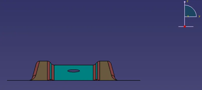
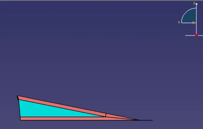
Image 1 : A-Surface in X-direction Image 2 : A-Surface in Y-direction
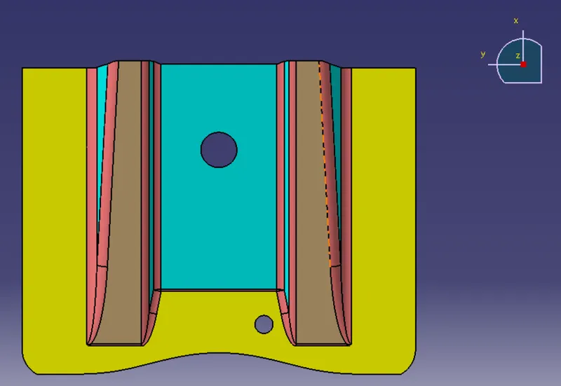
Image 3 : A-Surface in Z-direction
Creation of Tooling Axis:
The tooling axis is created by using Measure Inertia tool. The below steps explains in detail the procedure to be followed.
- Select Measure Inertia tool under Measure tool bar. A popup window as shown in below will be displayed.(See Image 4)
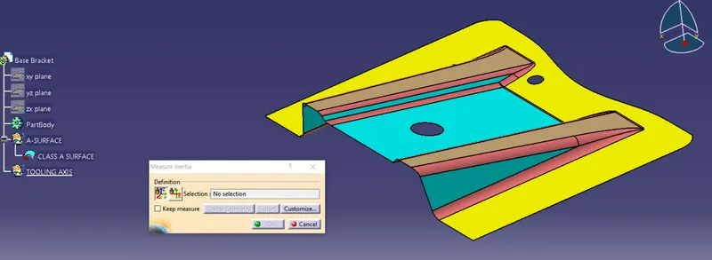
Image 4 : Measure Inertia selection window is seen in above image
- Select the "A-surface" in specfication tree and select "create geometry". (See Image 5)
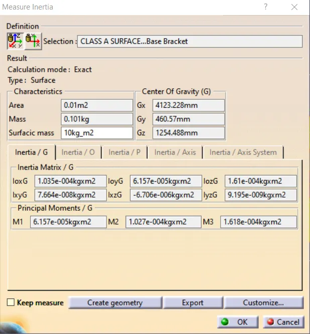
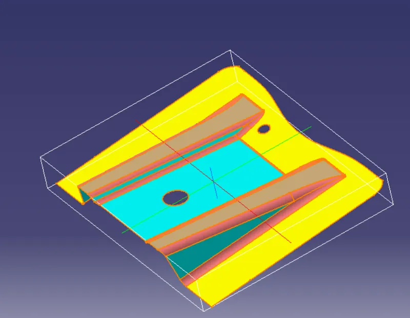
Image 5 : Measure Inertia Input window
- In creation of Geometry window, select Non-Associative Geometry. This will create a isolated point which wont get affected in case of change in A-surface.
Change Point type from explicit to coordinates.(See Image 6,7)
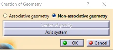
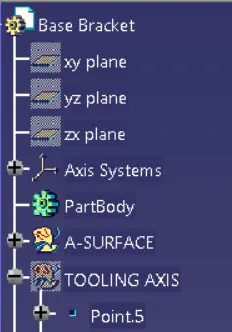
Image 6,7 : Creation of Geometry window ,Point created based on Measure Inertia Inputs
- Create Tooling axis line using Point-direction method,by selecting the point and Z-direction.(See image 8)
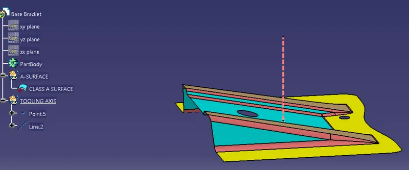
Image 8 : Creation of Tooling Axis
Draft analysis:
After the tooling axis is created, it is needed to analyze the tooling direction with respect to the surface and check if all the areas are meeting the draft angle requirement of 3 degree.
This method of analysis of draft angle based on tooling axis is called Draft analysis.
- The Feature Draft analysis tool present under Analysis tool bar was selected.
- In colourscale window,the value of 3 degree is entered.
- The mode selected was 2 angle with other value being 0 degree.
- The compass was placed in line with Tooling axis,lock button was switched on and the surface was selected.
- The surfaces were highlighted in green through which it was determined that all surfaces with respect to tooling axis will clear when draft angle is 3 degree. (See Image 9,10)
The Draft analysis of the part with the tooling axis was thus done by following above steps.
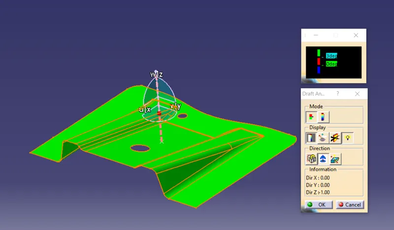
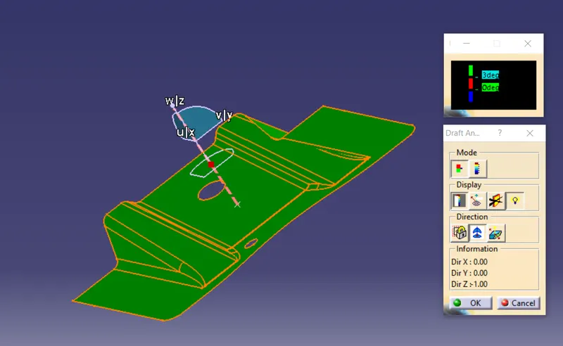
Image 9,10: Draft Analysis
Publication of A-surface and Tooling axis:
The tooling axis and A-surface are then published usingPublication option. This results in creation of new features under publication in specification tree.
This is done so that these important features can be easily accessed at later stages.(See Image 11)
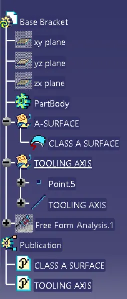
Image 11 : Publication shown in specification tree
Creation of B-surfaces:
The next step was creation of B-surfaces.
These surfaces were created under a geomertrical set named "B-surface". This set had different geomterical sets named based on the features created based on A-surface.This was done for better understanding
and clarity of the specfication tree. (See Image 12)
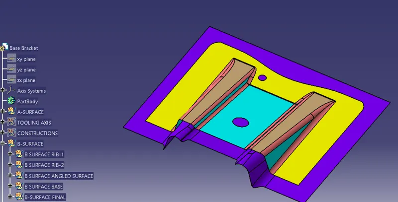
Image 12: Creation of B-surface
Intially, B-surfaces for the to ribs were created by extracting the surfaces and untrimming them. Then these surfaces were extrapolated to intersect with each other. Using trim command, these extrapolates
surfaces were trimmed as per the needed geometries. This resulted in a single trim which was offseted to a distance of 2.5 mm which is the thickness of the component.
The same steps were repeated for all surfaces to create B-surfaces. Then all the trims were combined as a single trim resulting in a single B-surface to which edge fillets were added.
The below images (See Images 13-17) shows the steps of B-surface creation. The Final B-suface created is shown in Violet colour (See Image 17).
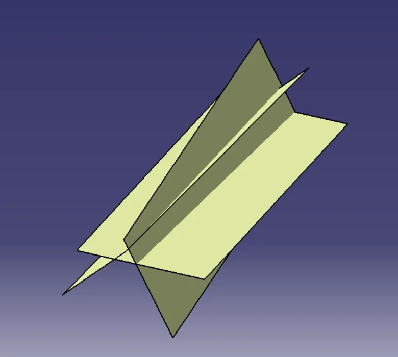
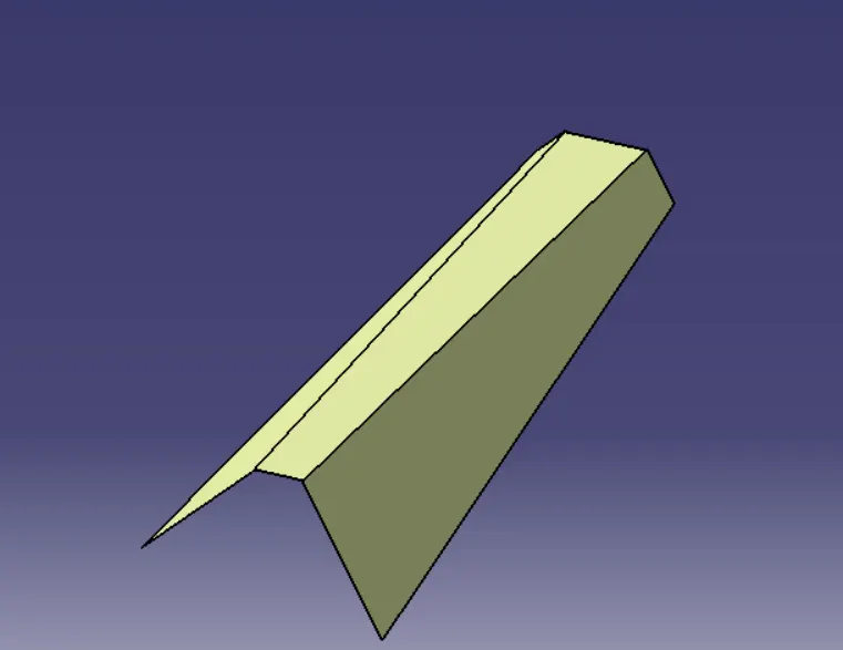
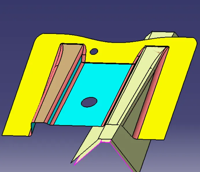
Images 13-17: Creation of B-surfaces
Creation of C-surfaces:
After creation of B-surfaces, C-surfaces were created. C-surfaces are surfaces which connects the A and B surfaces and results in a closed body. C-surfaces are create with reference to tooling axis.
The edges of A-surfaces and holes were selected to create a boundary which acts as a guide curve for C-surfaces.
Using sweep with draft direction, the tooling axis was selected for direction and draft angle of 3 degrees was entered. The direction of sweep was selected on the model by selecting the arrows as shown in below
images. (See Images 18-20)
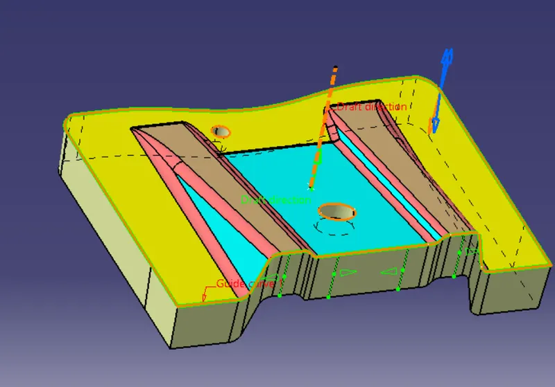
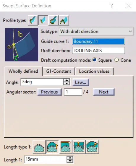
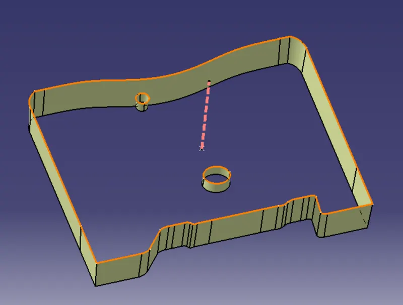
Images 18-20: Creation of C-surfaces
Final Surface Operations:
After the B and C surfaces were created, it was trimmed with A-surface to create a single body. To check if it is a closed body, Boundary option can be used. An error will pop up as shown in image (See Image 21)
saying it is a closed body.
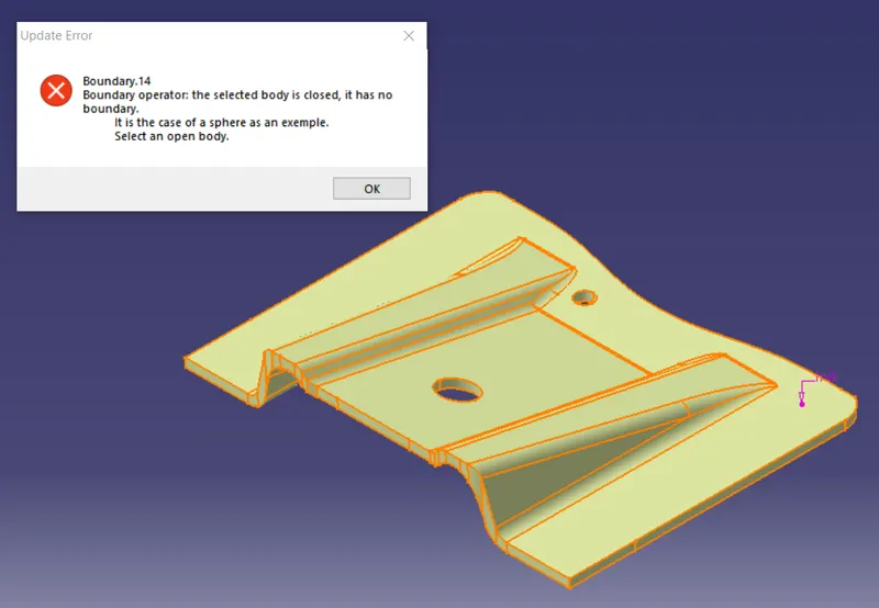
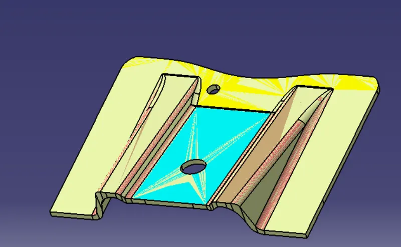
Images 21-22: Final closed body after trimming of A,B and C surfaces.
Creation of solid Body:
Then in Part design workbench, Using close surface in surface based features tool, a solid body is created b selecting the trimmed surface.(See Image 23)
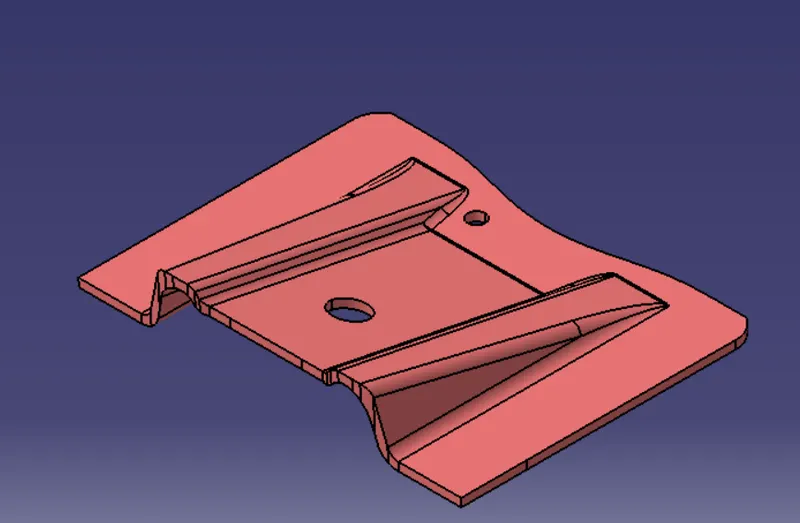
Image 23: Final solid body
Results:
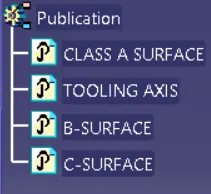
Image 23: Publication of A,B,C surfaces and Tooling axis
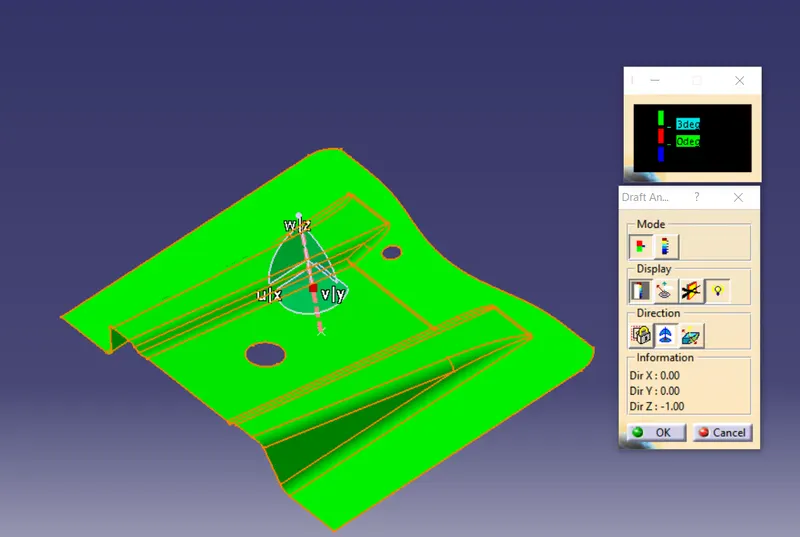
Image 24: Draft analysis of A surface
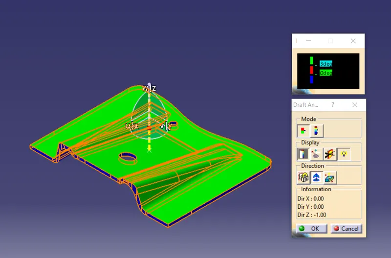
Image 25: Draft analysis of Solid Body
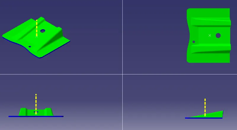
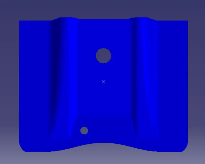
Image 26: Multi view of Brass Bracket with Draft colour
Conclusion:
Thus the Bass Bracket design was completed as per the inputs given and by following the steps with all the procedures needed to create a tooling axis,B surface,C surface and a final closed,solid body.
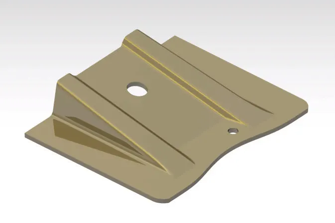
Image 27: Rendered view of Brass Bracket