Week 8-Challenge
3D MESHING ON THE GIVEN CAD MODELS USING TETRAMESH IN HYPERMESH
AIM: To create 3D mesh on a given CAD model using tetramesh as per the quality criteria in hypermesh
INTRODUCTION
When the CAD model is clean then no need go through the geometry clean-up but we need to check the geometry properly before extract the mid surface. Depending on complexity of the model, we can make the model symmetrical so that it is easy to work on the model.
When we change the mode of the component it looks completely transparent green color so delete the solids. Tools > delete > solids > click on delete entity. In shell mesh or 2D meshing we need to delete the solids but in 3D meshing we can mesh the solid model using volume tetra.
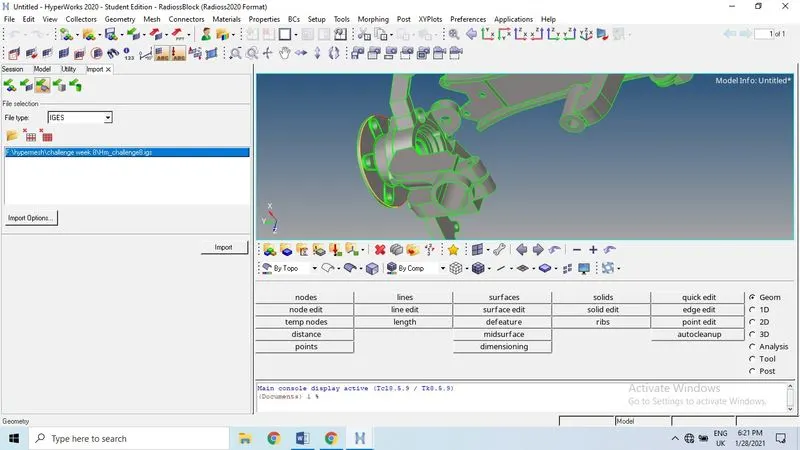
File (type) > Import > geometry or CAD model > select the link and click on import.
While Import the CAD model file (step , hm or IGES etc.) the model may have geometrical errors like unconnected, missing and duplicate surfaces also overlap surfaces due to small geometry areas in the model. Cleanup operations include the equivalence of "red" free edges, fixing of small surfaces (relative to the element size), and detection of features such as beads. It also performs specified surface editing or de-featuring operations like the removal of pinholes (less than specified size), removal of edge fillets, and the addition of a layer of washer elements around holes.
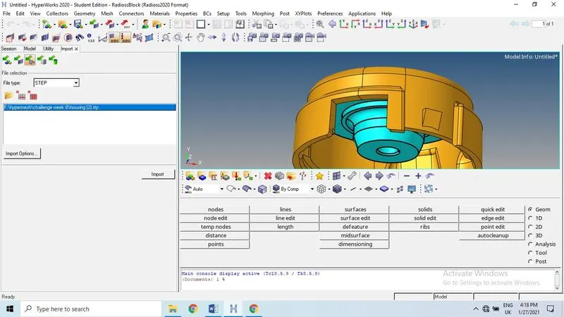
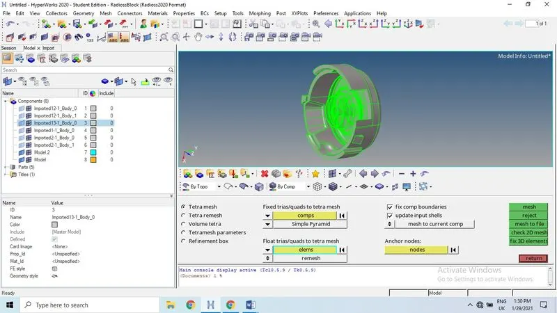
Auto cleanup: To use auto cleanup the geometry before meshing the model as per the criteria given... Below we can observe the CAD model with missing surfaces, sometime these are done by auto cleanup or manually we have to clean the geometry.
Geometry > auto cleanup> enter the target elemental length > select the model > click on auto cleanup
Manual cleanup: Sometimes we need to clean the geometry manually where auto cleanup not works properly.
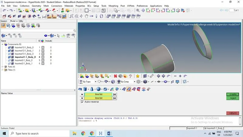
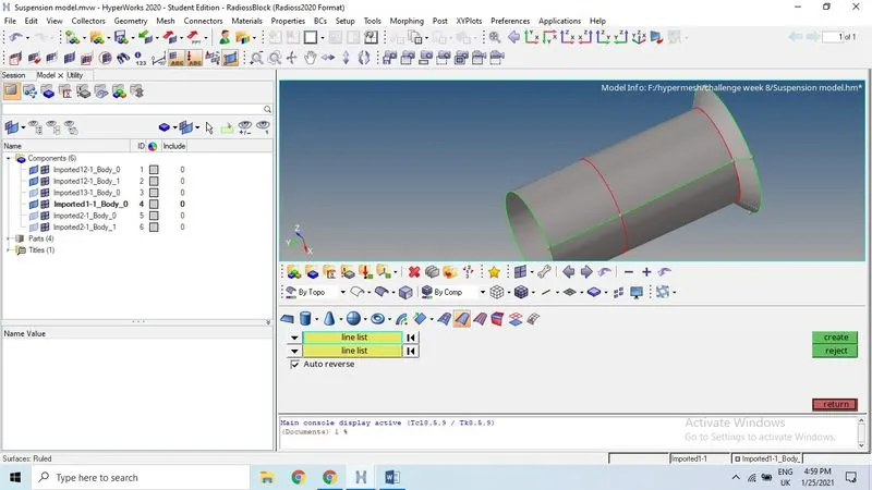
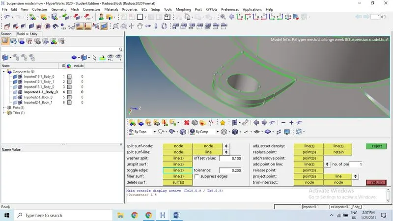
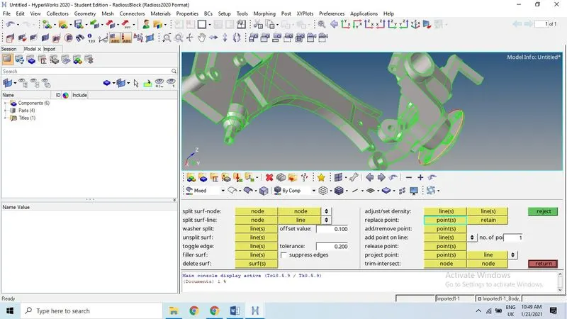
Meshing: Creating the mesh on 2D surface using auto mesh option here. Before we create the meshing we need to edit he criteria by using F12 in the keyboard or preference > criteria, parameters.
Size and Bias.
Use the Size and Bias subpanel to perform size and bias meshing, a flexible and powerful meshing method. A minimum of inputs are required for the element criteria settings.
Size and biasing meshing produces a mesh with consistent element size. If meshed interactively, the number of elements (element density) node spacing (biasing), element type and mesh style can be modified for each surface face and edge.
Use the Auto mesh panel to generate a mesh of plate elements using surface geometry or existing shell elements to define the mesh area.
I have used mixed elements instead quad and other elements available.
Uses quads primarily, but inserts trias when making density transitions, resulting in improved mesh quality. I have used mixed elements here to improve the mesh quality and it’s easy to work on surface mesh.
Set the options in the panel in any order that you feel comfortable using. Moving from subpanel to subpanel will not cause you to lose work. When you are finished making all your selections, click mesh to start the meshing process.
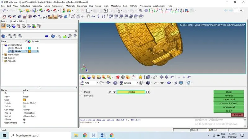
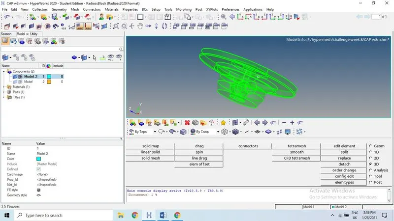
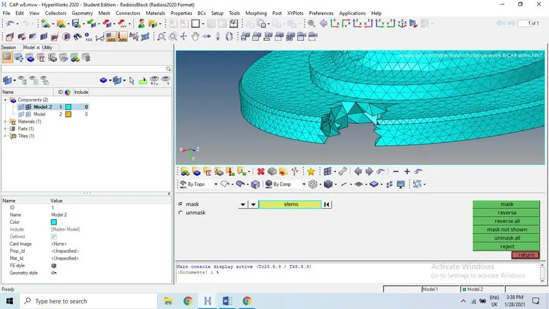
This is solid model, we can mesh this using volume tetra without shell mesh
For 2D mesh cleanup
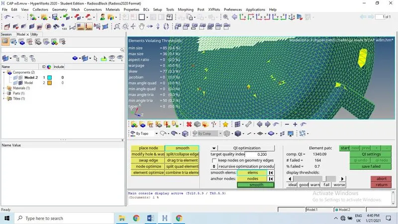
Cleanup tools:
The Quality Index Cleanup Tools secondary panel's layout changes dynamically depending on the cleanup tool you select.
To meet the quality these cleanup tools make use to change or modify the elements and node in particular direction and place, it helps to reduce the errors.
Place node: To move nodes along the surface or normal to the surface.
Modify the hole or washer tool: To modify the elements or nodes around the hole without changing the hole radius and also moving the washer elements to modify the radius and angular movement of the element.
Swap edges: Use the Swap Edge tool to consider the elements to which the edge belongs, and find alternative orientations for it. To improve the mesh quality and rectify the fail elements. For a pair of trias, there are two possible positions for their shared edge. For a pair of quads, there are three possible positions. For a quad and a tria, there are six possible positions.
Smooth: To improve the mesh quality of surface based mesh.
Node optimize: Use the Node Optimize tool to automatically move a selected node to optimize the overall quality of its surrounding elements. The options along surface, normal to surface, and along and normal to surface work exactly as described for the place node tool. The only difference is that node optimize moves the node automatically, while place node requires you to choose the location manually.
Element optimize: Use the Element Optimize tool to automatically optimize the shape of the selected element and the elements surrounding it. It is similar to Node Optimize, except that its effects are wider-spread.
Drag tria: To move the trias from one location to another or out of location.
Split quad: sometime quad elements are out of size then we can split the quad by click on the quad element.
Edit element also used here to do similar kind of function, like create, combine and split. 2D> edit element>create (quad, trias, hexa. Etc.) Or combine or split the element.
Save the failed elements then we can retrieve the elements to rectify the error in that particular elements. Quality > clean up tools > save failed > mask > elements > retrieve > mask > reverse.
3D meshing
A region is considered enclosed if it is entirely bounded by a shell mesh (tria and/or quad elements). Other element configurations generated in this panel are hexahedral, wedge, and pyramids. These elements are typically generated when you need boundary layer type meshes on certain areas of the volume surface.
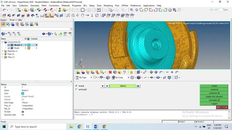
3D > Tetramesh > we tetramesh, tetraremesh, volume tetra and tetramesh parameters
Tetra mesh: Use the Tetra Mesh subpanel to fill an arbitrary volume, defined by its surface using tria/quad elements, with tetrahedral elements.
Tetra remesh: Use the TetraRemesh subpanel to regenerate the mesh for a single volume of tetrahedral elements.
The Free boundary faces option affects those faces of tetra elements which are on the outside of the volume, meaning the tetra faces which have only one tetra attached. Those faces are called free boundary faces.
Volume tetra: Use the Volume Tetra subpanel to generate a shell mesh and fill the enclosed volume with solid elements.
When you select quads or mixed as your 2D element type, HyperMesh creates quad elements and splits them diagonally into two trias during tetra face creation. This can create tetra elements whose triangular faces are right triangles (90-45-45 angles) instead of equilateral triangles (60-60-60 angles).
Given a solid entity or a set of surfaces representing a closed volume, this meshing option generates a shell mesh and fills the enclosed volume with solid elements. You can choose to create a shell mesh (2D) using quads, trias, or mixed elements and a solid mesh (3D) using tetrahedral elements only or mixed (tetras and penta) elements. In addition, you can use proximity meshing, which refines the mesh in areas where the features are small and closer together.
Tetramesh parameters: Use the Tetramesh Parameters subpanel to set general qualities of the tetra meshing engine, such as a maximum element size, growth rate, the balance between speed and element quality, or whether to perform smoothing operations after initial meshing.
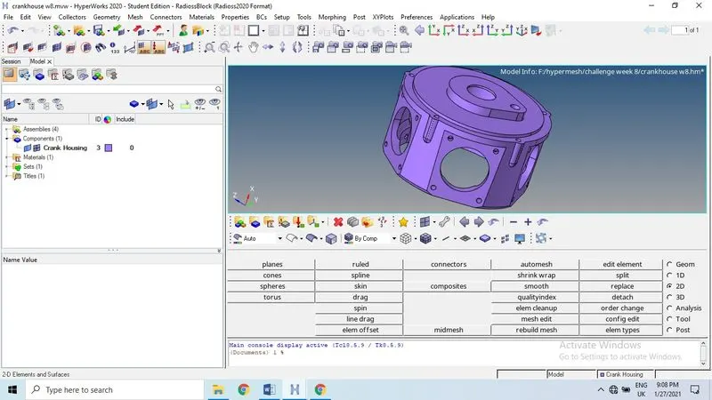
The given CAD model meshed with 2D meshing or shell mesh before going for 3D mesh.
3D > Tetra mesh > click on dropdown icon to select the elements or comp > select the type of element by click on dropdown icon.
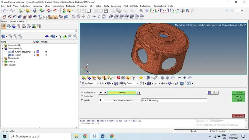
We can check the 3D elements formation after tetra mesh is done on the surface mesh. We have to give the elemental size as per the criteria.
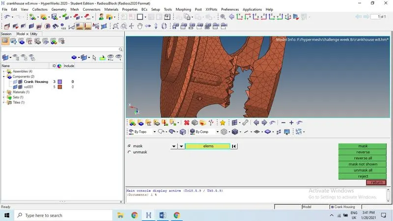
Using volume tetra has two type of meshing possible , one is surface and other one is solid so the given component is not solid then we can directly mesh the 3D meshing on the model. Here the component is directly meshed without shell mesh here.
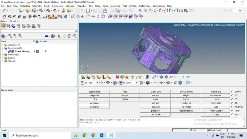
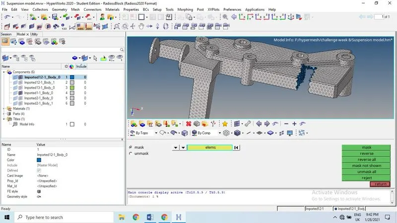
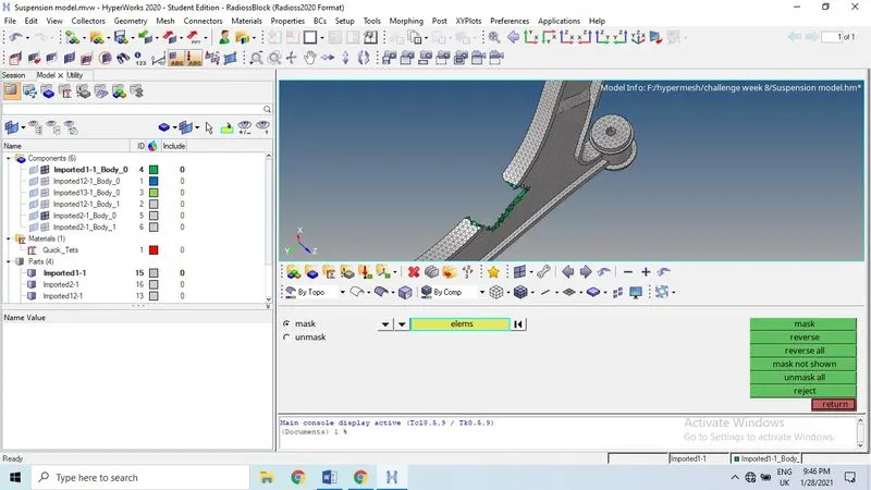
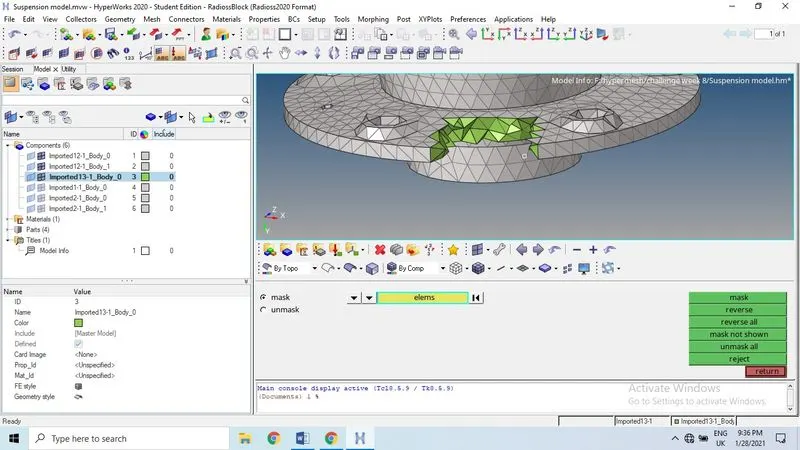
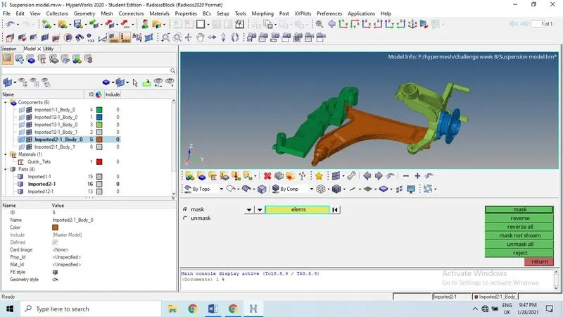
Outcomes:
- Learned manual geometry cleanup for 3D mesh
- Learned 2D to 3D meshing using tetra mesh and volume tetra etc.
Conclusion: Geometry cleanup and 3D tetra meshing on CAD model is done as per the given quality criteria.