Week 8 Challenge
AIM: - To calculate the load applied at the base of pile foundation as per the guidelines given by IRC-6
LOAD CALCULATION: -
Given Data: -
| Basic design details | ||
| 1 | Basic design data | |
| 1.1 | Span and cross-section data | Left span |
| C/C of expansion gap | 30 m | |
| C/C of bearing | 28 m | |
| Distance of bearing to expansion gap | 1 m | |
| Girder overhang beyond bearing | 0.35 m | |
| Total deck Width | 12 m | |
| Carriageway width | 11 m | |
| Footpath Width | 0 | |
| Crash Barrier Width | 0.5m | |
| Width of median | 0 | |
| 2 | Superstructural details | Left |
| Number of girders | 4 | |
| spacing of girders | 3m | |
| Cantilever on both sides | 1.5m | |
| Depth of superstructures | 1.32m | |
| C.G of superstructure | 0.88m | |
| Wearing coat thickness | 0.065m | |
| Distance of FRL from bearing of least height | 10.9m | |
| Bearing Thickness | 0.25m | |
| Pedestal thickness | 0.25m | |
| Superelevation | 2.50% | |
| 3 | Levels | |
| HFL | 232.1 | |
| Bed Level | 231.5 | |
| Road level | 232.361 | |
| Minimum vertical clearance needed | 4 m from dwg | |
| Soffit Level | 238.172 | |
| Pier cap top | 237.672 | |
| Pier top | 237.072 | |
| Height of Substructures | 5.211 m | |
| pile cap top level | 231.861 | |
| Depth of pile cap | 1.5 m assume | |
| Pile cap bottom level | 230.361 | |
| Clear cover for foundation | 75 | |
| Height of substructures | 5.5 m | |
| 4 | Water Current Data | |
| Max.mean velocity | 0.98 m/s | |
| Constant "k" for the pier in the transverse direction | 0.66 | |
| Constant "k" for the pier in the longitudinal direction | 1.5 | |
| % of uplift considered | 100% | |
| 5 | Material Used | |
| Grade of concrete fck | M35 | |
| Design of concrete fcd | 15.63 Mpa | |
| Grade of steel fyk | Fe500 | |
| The design strength of steel fyd | 434.8 Mpa | |
| The density of RC Concrete | 2.5 t/m3 | |
| The density of wearing the coat | 2.2 t/m3 | |
| Coef. Of thermal expansion of steel | 1.2 E-05/ºc | |
| Shrinkage strain of concrete | 2.00E-04 | |
| Modulus of elasticity of steel Es | 20000000 Mpa | |
| Modulus of elasticity of concrete Ecm for M35 | 32000 Mpa | |
| Mean axial tensile strength of concrete fctm | 2.8 Mpa | |
| Density of concrete | 2.5 t/m3 | |
| The density of wearing the coat | 2.2 t/m3 | |
| 6 | Soil parameters | |
| The density of dry backfill | 2 t/m3 | |
| Density of submerged backfill | 1 t/m3 | |
| Net SBC | 25 t/m3 | |
| Gross SBC (LWL) | 33.92 t/m3 | |
| Gross SBC (HFL) | 27 t/m3 | |
| Net sbc-seismic case | 31.25 t/m3 | |
| Gross SBC-Seismic case | 33.25 t/m3 | |
| Type of soil | medium soil | |
| Partial safety factor | |||
| Materials | Basic combinations | Seismic combination | |
| Concrete | 1.5 | 1.5 | |
| Reinforcement | 1.15 | 1.15 | |
| Load on superstructure | |||
| Dead load | |||
| Total weight of superstructure | 199t | ||
| DL reaction | 99.5 t | ||
| Total reaction on the abutment | 99.5 t | ||
| Unbalanced Long. Moment | 0 tm | ||
| Transverse ecc.of DL from pier c/l | 0 m | ||
| Transverse moment due to unbalanced DL | 0 tm | ||
| SIDL (Except WC) | |||
| Weight of crash barrier | 1 t/m | ||
| Weight of crash barrier | 60 t | ||
| Weight of median | 0.00 t | ||
| Weight of footpath | 0 t | ||
| Total reaction on the abutment | 30 t | ||
| Total Long.Moment | 0 t | ||
| Transverse ecc.of CB | 0 t | ||
| Total Trans. Moment | 0 t | ||
| SIDL (WC) | |||
| Load intensity due to WC | 0.22 t/m2 | ||
| Weight of WC | 77.60 t | ||
| Total reaction on the abutment | 36.30 t | ||
| Unbalanced long. Moment | 0 tm | ||
| Transverse ecc.of WC | 0 m | ||
| Trans. Moment due to unbalanced WC | 0 tm | ||
| Substructure | |||||
| Abutment | |||||
| Length (Longitudinal) | 12 m | ||||
| Length (Transverse) | 1.3 m | ||||
| Height | 0.3 m | ||||
| Volume | 4.68 m3 | ||||
| Weight | 11.70 t | ||||
| Trapezoidal Part | |||||
| Top length | 12 m | ||||
| Bottom length | 7 m | ||||
| Top width | 1.3 m | ||||
| Bottom width | 1.3 m | ||||
| Height | 0.3 m | ||||
| Volume | 3.66 m3 | ||||
| Weight | 9.15 m | ||||
| Total weight of pier cap | 20.85 t | ||||
| Pier shaft | |||||
| Dimension along traffic direction | 1 m | ||||
| Dimension perpendicular to traffic | 7 m | ||||
| Area of the rectangular part | 7 m2 | ||||
| height | 5.50 m | ||||
| Volume | 38.50 m3 | ||||
| Area-semicircular | 0 m2 | ||||
| height | 5.50 m | ||||
| Volume | 0 m3 | ||||
| Weight of pier | 96.25 t | ||||
| Total weight of substructure | 117.10 t | ||||
| Foundation | |||||
| Type of foundation | Pile | ||||
| Diameter of pile | 1 m | ||||
| no of the pile in each direction | 3 nos | ||||
| spacing of pile in each direction | 3 m | ||||
| size of pile cap | 7.3*7.3 m | ||||
| the thickness of pile cap | 1.5 m | ||||
| weight of pile cap | 199.84 t | ||||
| Weight of soil on pile cap | |||||
| Road level | 232.361 | ||||
| Pile cap top level | 231.861 | ||||
| Depth of soil above pile cap | 0.5 m | ||||
| The total volume of footing | 26.645 m3 | ||||
| Total weight of footing | 53.29 t | ||||
| Live load | |||||
| 1 Lane 70R wheeled | |||||
| Live load reactions | |||||
| Total live load | 100 t | ||||
| No of lanes | 3 lanes | ||||
| % reduction in live load | 10% reduction | ||||
| Impact factor-1L 70R | 1.13 as per IRC-6 | ||||
| Ra | 75.3 t | ||||
| Rb | 26.4 t | ||||
| Vertical reaction on the abutment | 75.3 t | ||||
| Braking force | 20% of 75.3 t | = | 15.06 t | ||
| Total horizontal force at bearing level | Fh/2 | = | 7.53 t | ||
| Longitudinal moment | 75.3 tm | ||||
| Bearing type | POT, PIFE | ||||
| Transverse eccentricity | 3.405 m | ||||
| Transverse moment | 256.40 tm | ||||
| 1 Lane Class A | |||||
| Live load reactions | |||||
| Total live load | 55.4 t | ||||
| No of lanes | 3 lanes | ||||
| % reduction in live load | -- | ||||
| Impact factor-1L 70R | 1.125 as per IRC-6 | ||||
| Ra | 39.88 t | ||||
| Rb | 16.21 t | ||||
| Vertical reaction on the abutment | 39.88 t | ||||
| Braking force | 20% of 39.88 t | = | 7.967 t | ||
| Total horizontal force at bearing level | Fh/2 | = | 3.988 t | ||
| Longitudinal moment | 39.88 tm | ||||
| Bearing type | -- | ||||
| Transverse eccentricity | 4.7 m | ||||
| Transverse moment | 187.444 tm | ||||
| 3Lane 70R wheeled | |||||
| Ra | 119.64 t | ||||
| Rb | 48.63 t | ||||
| Vertical reaction on the abutment | 119.64t | ||||
| Braking force | 20% of 2*39.88+5% of 39.88 | = | 17.946 t | ||
| Total horizontal force at bearing level | Fh/2 | = | 8.973 t | ||
| Longitudinal moment | 119.64 tm | ||||
| Bearing type | -- | ||||
| Transverse eccentricity | 1.2 m | ||||
| Transverse moment | 143.57 tm | ||||
| Summary | |||||
| Live load case | Vertical load in t | ML in tm | MT in tm | HL in t | HT in t |
| 1lane 70R wheeled | 75.3 | 75.3 | 256.4 | 7.53 | 0 |
| 1L class A | 39.88 | 39.88 | 187.44 | 3.988 | 0 |
| 3L class A | 119.64 | 119.64 | 143.57 | 8.973 | 0 |
| Summary | |||||
| Load case | Load P | ML | MT | HL | HT |
| t | tm | tm | t | t | |
| DL | 99.5 | 0 | 0 | 0 | 0 |
| SIDL | 30 | 0 | 0 | 0 | 0 |
| SIDL (WC) | 36.3 | 0 | 0 | 0 | 0 |
| Weight of substructure | 117.1 | 0 | 0 | 0 | 0 |
| Weight of pile cap | 199.84 | 0 | 0 | 0 | 0 |
| Weight of soil above pile cap | 53.29 | 0 | 0 | 0 | 0 |
| LL1 | 75.3 | 75.3 | 256.4 | 7.53 | 0 |
| LL2 | 119.64 | 119.64 | 143.57 | 8.97 | 0 |
2) List all the components of the well foundational list the kg/cumec in them.
Also, list their functionality in respect to bridge loadings.
Draw a sketch for each component.
Aim: - List all the components of the well foundational list the kg/cumec in them.
The following are the components of well foundation,
- Well cap
- Top plug
- Steining
- Bottom plug
- Well curb
- Cutting Edge
- Filling (Sand/water)
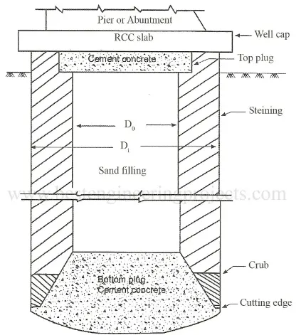
Credit:- https://bestengineeringprojects.com/component-parts-of-a-well-foundation/
Well Cap
- It consists of an RCC slab on the top of the steining. It transmits loads from pier to wall.
- Mostly it is circular in shape. In the case of the abutment, octagonal & hexagonal-shaped wells can also be used.
- The top of well cap should be at bed level or 500mm below ground level.
- The bottom of the well cap shall be laid as low as possible but above the LWL in the active channel.
Top plug
- A minimum concrete grade of M15 is used.
- In order to make it stable, sand/water filling is used.
- In the case of clayey strata, to bifurcate sand and empty space, an intermediate plug is used.
Steining
- The thickness of the steining should be such it is possible to sink the well without excessive kentledge and without getting damaged during the sinking.
- The steining should also be able to resist differential earth pressure developed.
- The minimum concrete grade is M20 with cement content not less than 310kg/m3.
- It forms the body of the well. It is used to transfer the load to the base of the foundation.
- Generally, RCC cracked sections are used. In the case of the uncracked section, minimum reinforcement has to be provided.
- The minimum thickness of the wall steining shall not be less than 500mm & satisfy the following relationship.
- h=Kdsqrt(l)
- K= a constant
- l = Depth of wall in meters below the top of well cap.
Bottom Plug
- After sinking the well, the base of the well is plugged with concrete.
- A minimum grade of M15 is used.
- The thickness of the bottom plug shall not be less than half of the well diameter.
- The concrete mis used in the bottom plug shall have a minimum cement content of 330kg/m3.
Well curb
- The well curb should be strong enough to be able to transmit superimposed loads from the steining to the bottom plug.
- It is a wedge-shaped RCC ring beam. It helps to sink then well foundation properly.
- The internal angle of the curb should be kept at about 30-37 degrees.
- The well curb shall be in RCC with a minimum grade of M25 and minimum reinforcement of 72kg/cumec.
Cutting Edge
- The mild steel cutting edge shall be strong enough & not less than 40kg/m to facilitate the sinking of the well.
- It is fitted with a mild steel angle of 150mm size, which is protected by a 6mm inner plate & a 10 mm outer plate.