Creating the 3d tetrahedral elements on a given models by using HYPERMESH
AIM :
To Creating the 3d meshing on a given model and checking the minimum tet collapse element parameter for all components.
OBJECTIVE :
1) Geometry cleanup on a surface if it's required.
2) Create a 2d meshing on a given model surface, if the minimum and maximum quality parameters are consider.
3) Create a 3d meshing from 2d elements and check the minimum tet collapse quality parameter.
4) Create a 3d meshing on a model without 2d reference by using Volume tetra option and check the minimum tet collapse quality parameter.
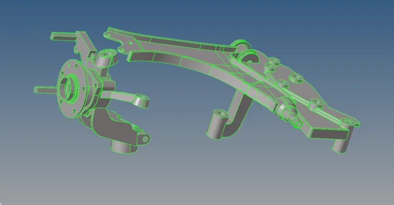
CAD MODEL IMAGE :
I) Model 1
1) Open a Hyperworks software and set the user profile which depends on components gets deformation. If a deformation is small, we gonna to perform a "Optistruct" user profile which is implicit solver and if a deformation is large, we gonna to perform a "RADIOSS" user profile which is explicit solver.
2) Click the "Import Solver Deck" option from where tool bar section, then select the "import geometry" option and select the file type which is "STEP" because given model has "STP" format. Click the folder option and select the respective file which will going to perform and then click the "Import option" it showing up the components from graphical window.
3) After importing the model, by default "Auto" geometry color mode had selected. For visualizing the topologies, manually change into "By Topo" mode for viewing the "Free edges, Sharped edges, T Junction edge and Supressed edge" from components.
4) In this model have two components which are inner and outer components.
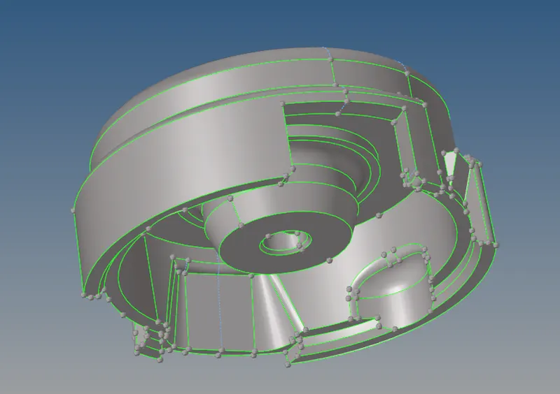
i) Outer Component :
This is the surface component, so directly gonna perform 2d meshing operation on it after complete the manual geometry cleanup.
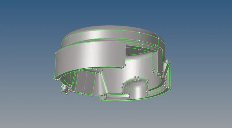
ii) Inner Component :
Initially this component have solids, we need only surface. So, we manually delete the solids from this particular component by using delete option.
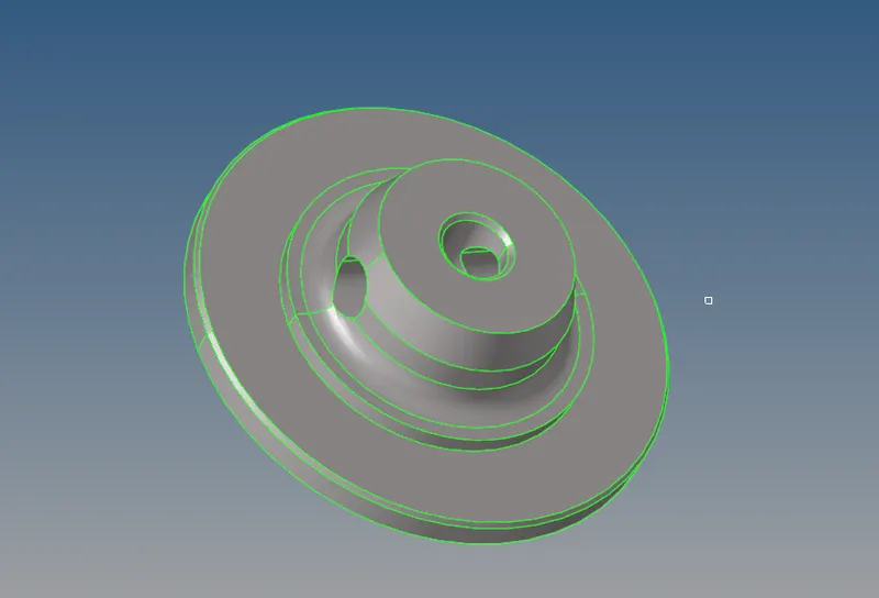
II) Model 2
1) Click the "Import Solver Deck" option from where tool bar section, then select the "import model" option. Click the folder option and select the respective file which will going to perform and then click the "Import option" it showing up the components from graphical window.
2) After importing the model, by default "Auto" geometry color mode had selected. For visualizing the topologies, manually change into "By Topo" mode for viewing the "Free edges, Sharped edges, T Junction edge and Supressed edge" from components.
3) In this model have only one component and also this is surface component. So, we directly go to geometry cleanup or meshing operation.
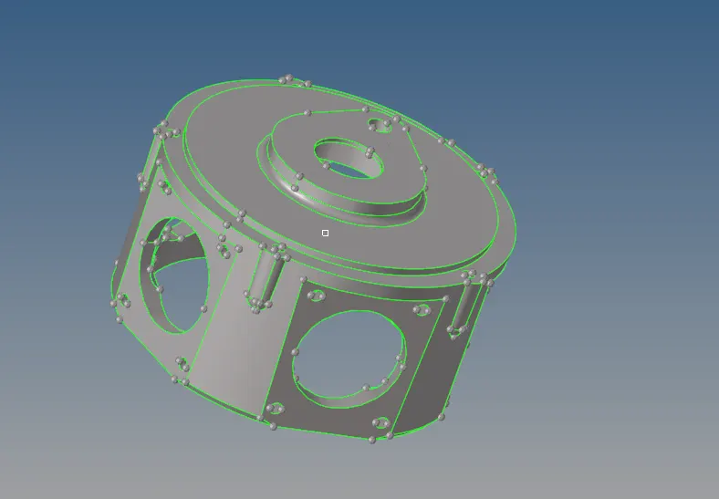
III) Model 3
1) Click the "Import Solver Deck" option from where tool bar section, then select the "import geometry" option and select the file type which is "IGES" because given model has "iges" format. Click the folder option and select the respective file which will going to perform and then click the "Import option" it showing up the components from graphical window.
2) After importing the model, by default "Auto" geometry color mode had selected. For visualizing the topologies, manually change into "By Topo" mode for viewing the "Free edges, Sharped edges, T Junction edge and Supressed edge" from components.
3) In this model have consist of four components and all are surfaces. So, we directly go to 3d meshing operation.
PROCEDURE TO ACQUIRING THE OBJECTIVES :
I) Cleanup the given model :
i) Model 1 :
1) For model 1, we have supressing few sharped edge line and also create a new few lines on a model for which restrict the element failing due to minimum element length criteria and as well maximum element length criteria by using "Toggle option" and also "Surf Split line" or "Surf Split node" option.
2) A outer component only needed for some geometry cleanup, for inner component has no needed for geometry cleanup on it. Because, two parallel feature line lateral distance not comes under the given element criteria.
ii) Model 2
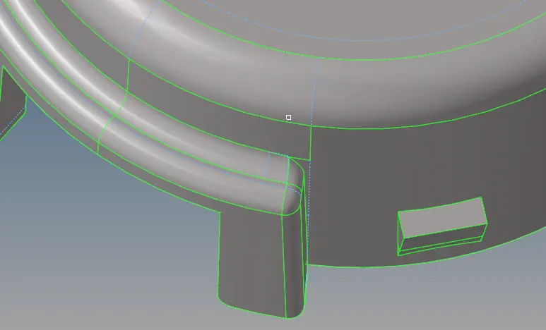
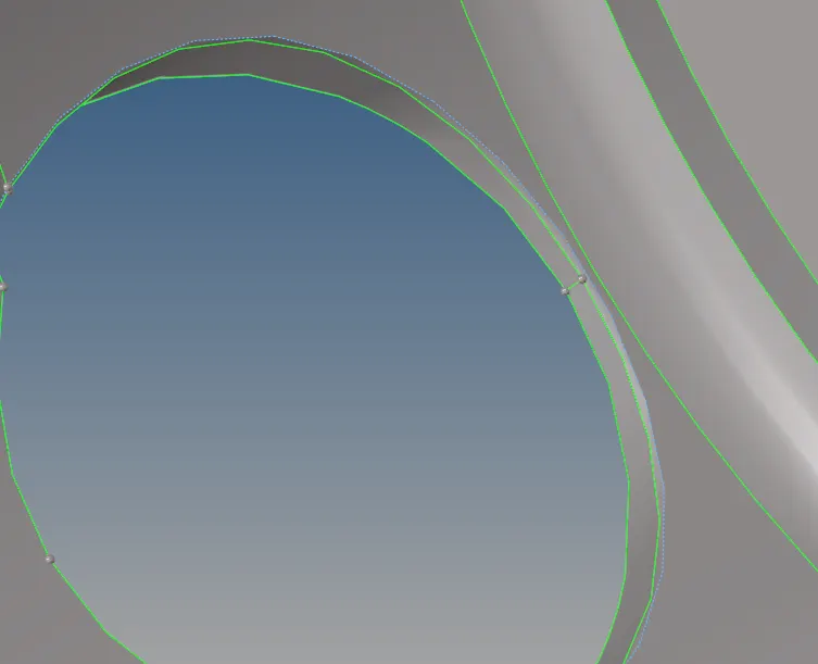
1) In this model have some free edge were found, it's not desirable to perform meshing operation. So, we want to toggling on a free edge feature line for converting into sharped edge feature line.
Before After
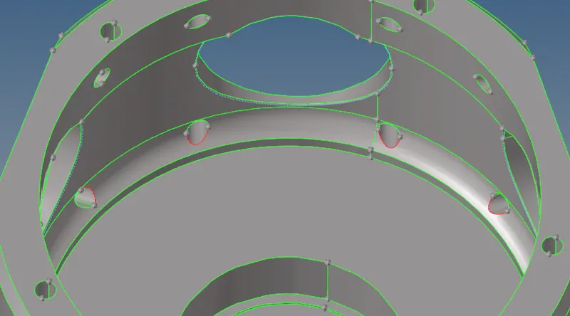
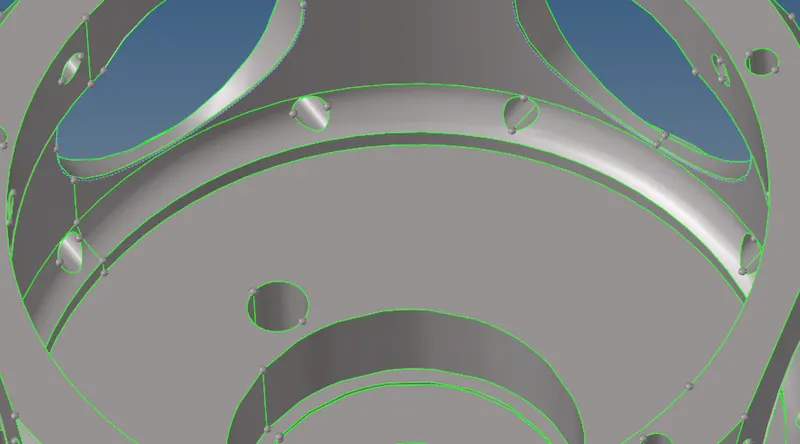
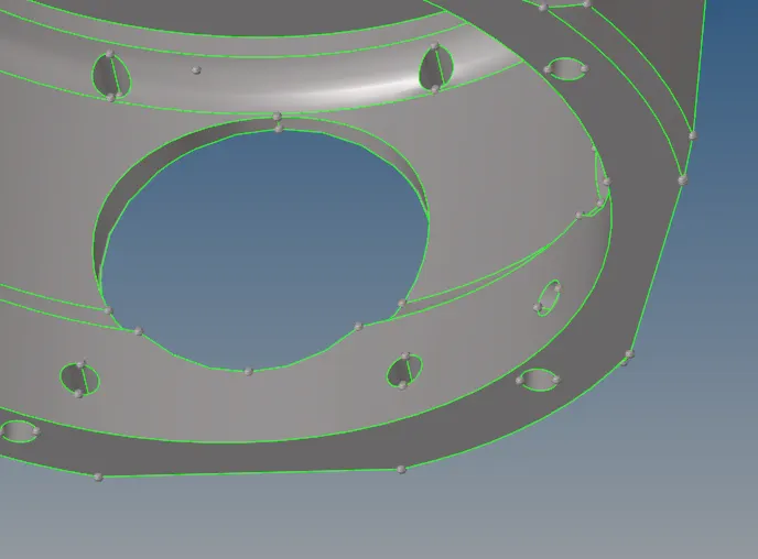
2) In this particular area, one of the champer line had already supressed, We has to manually unsupressing those feature line and combine the two point by using replacing point option.
3) After done this process, a getting the proper model for perform 3d meshing.
Before After
iii) Model 3
I) Component 1 :
1) We have to remove the inner teeths by manually, because it cause to failing tet collapse also. Go to delete option or else press "F2" from the keyboard, set the surface option instead of element from the selector bar.
2) Select the surfaces which are wants to delete and click to delete it.
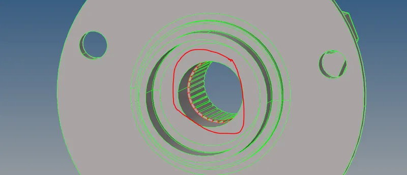
3) After deleting the teeth surfaces, we have to extend the surface between the feature line. Make sure masking the particular surfaces, it will help us to view properly.
4) Go to "Extend" sub panel under which "Surface edit" panel, select the free edge line and destination surface to click to create a surface on between those free edges.
5) After extending the line between those few edges, still a surface has not connect properly together. So, we use toggle option to fix the issues on that particular region.
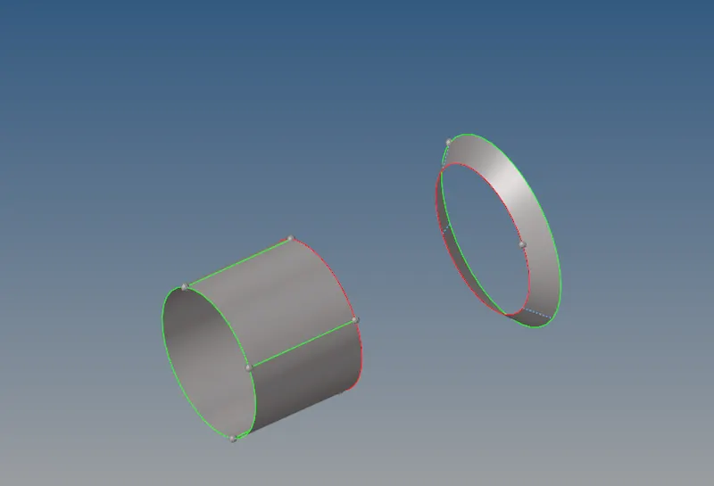
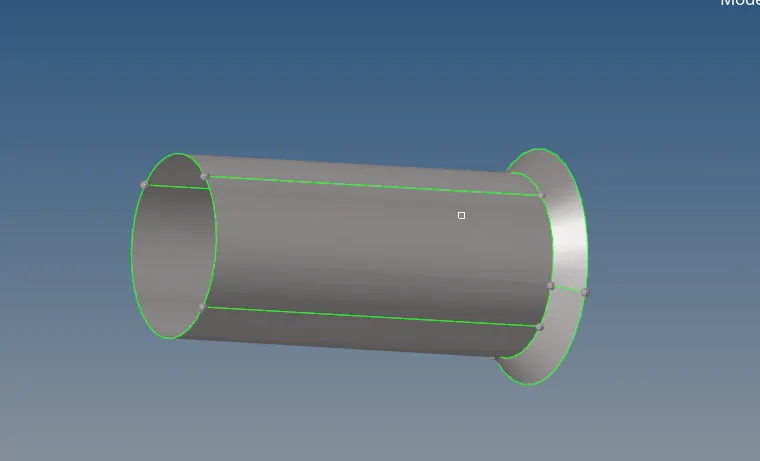
6) After extending the surface, a surface will looks like same as below image. Then unmasking it.
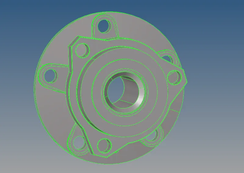
7) After geometry cleanup had been done, a component is ready for meshing and it's looks like below image.
ii) Component 2 :
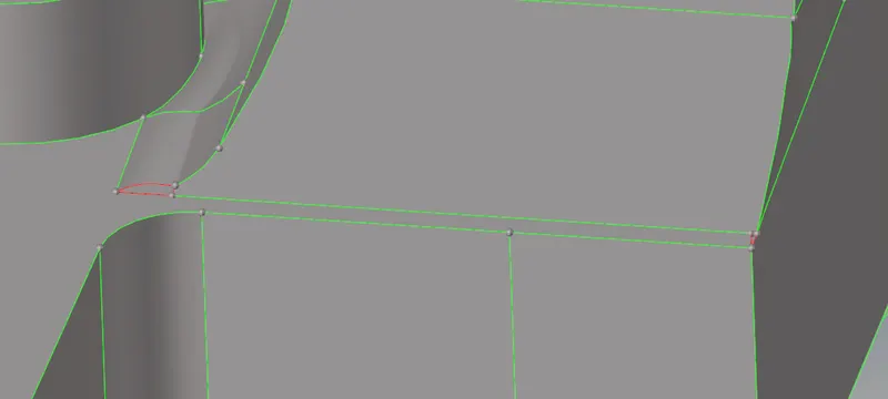
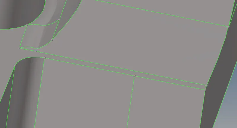
In this component, a surface has missing at where some few areas. By using filler option and toggle option to fix these issues.
Before After
II) Creating the 2D shell elements :
1) In this model, we have consider minimum and maximum element length criteria. So that, we perform 2D meshing on this surface by using "AutoMesh" panel under the "2D" Main menu panel.
2) Set the element size is 5mm and element type is 'trias'
3) Selecting any one of the surface from this housing inner component and then perfom meshing operation on it, subsequently check the qualities for minimum and maximum element length. If created element were failing due to minimum or maximum element criteria, we should work on it to get good elements. Similarly, do the same procedure throughout the component.
4) This meshing procedure is same for both inner and outer component.
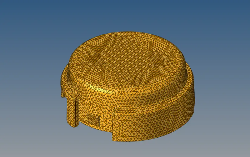
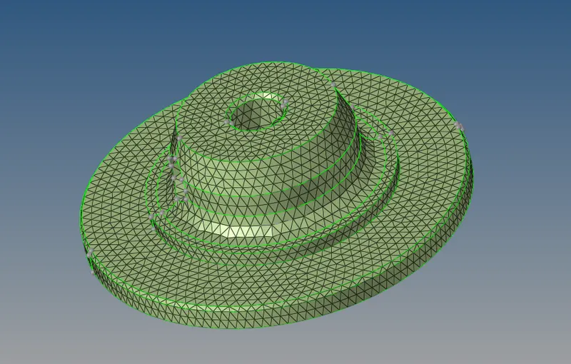
Quality Checking :
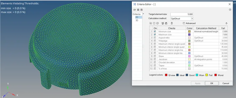
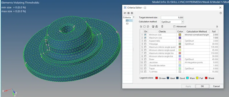
1) Make sure the assigning the element criteria for minimum and maximum through which "Criteria file setting" under the "preferences" option fromt the header menu.
2) In this case, we only consider minimum and maximum element length criteria. All created elements are passed the given element criterias.
III) Creating the 3d elements from 2d elements for only model 1 :
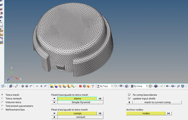
1) For creating the 3d elements from which reference of 2d elements, go to the "Tetramesh" panel under the "3D" main menu panel. Select the "Tetra Mesh" sub panel under which "tetramesh" panel, select the 2d shell element which are presented on the surface.
2) Set into "Mesh to current component" for 3d element will appeared on a current component. Make sure select the current component properly before perform a meshing operation.
3) Click to mesh, a tetrahedral element are created on a model by using reference of 2d shell elements.
4) Similarly, select the inner component 2d shell element as well and perform meshing operation on it.
Quality Check :
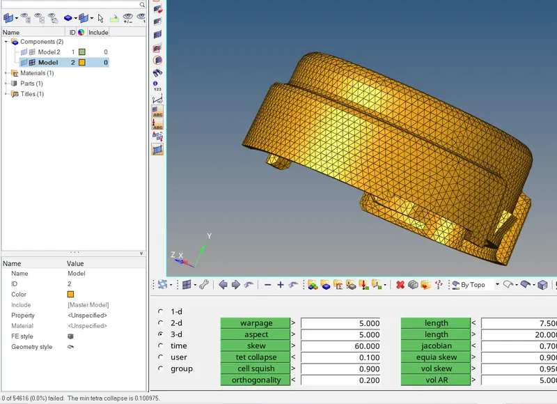
1) For 3d elements, we only take care of 'tat collapse' parameters which is height of the top node from the base surface of the element. All tetra elements will have satisfied and goes above the minimum tat collapse parameter value which is 0.150.
2) In this component, a 3d tetra elements are satisfied the tat collapse element parameter.
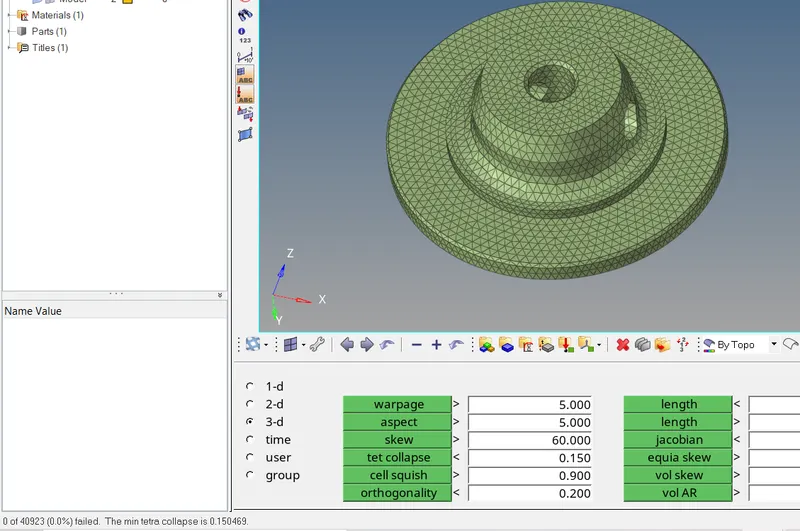
3) Similarly, put the same value of tet collapse and rectifying the failing issues.
IV) Directly create the 3d element for model 2 & 3 :
Model 2 :
1) In this model have only one component and also no need to consider the element criteria except Tet collapse. Inorder to create a 3d element, select the "Volume Tetra" sub panel under which "tetramesh" panel.
2) Change into surface instead of solid from the selector bar, provide the appropriate element size and check the "Cleanup elements". A 2d type is trias and 3d type is tetras and then select first order.
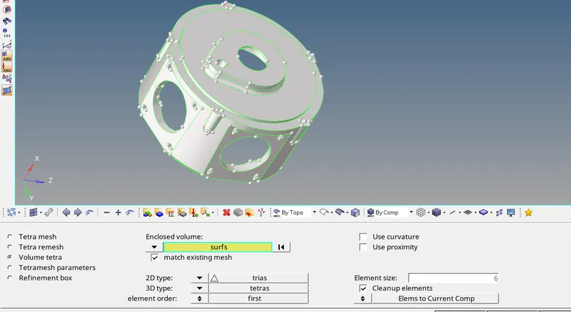
3) Before going to perform meshing operation, make sure put the given tet collapse value on respective place and also provide the maximum tetra size.

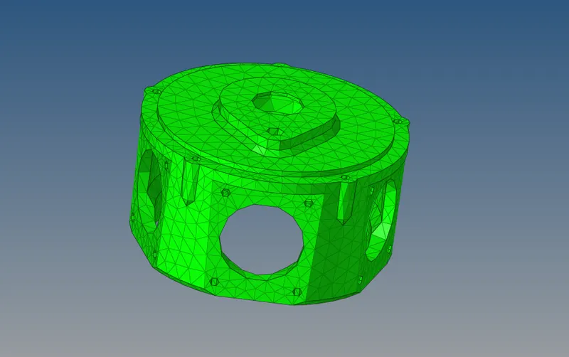
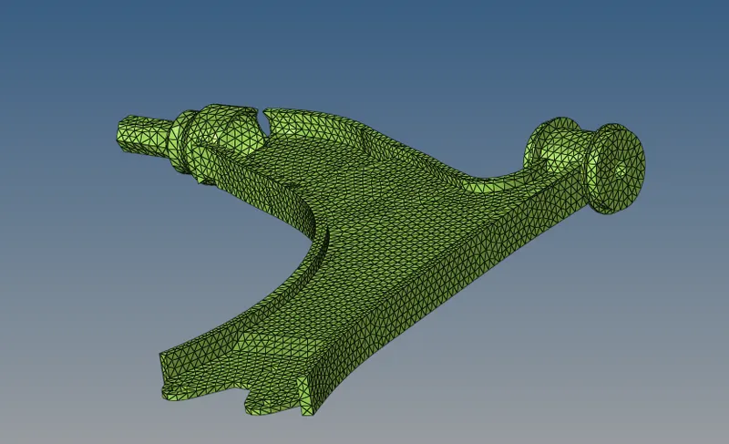
4) After execute the meshing operation, a meshed elements are looks like below image. Now, we gonna checking the tet collapse parameters.
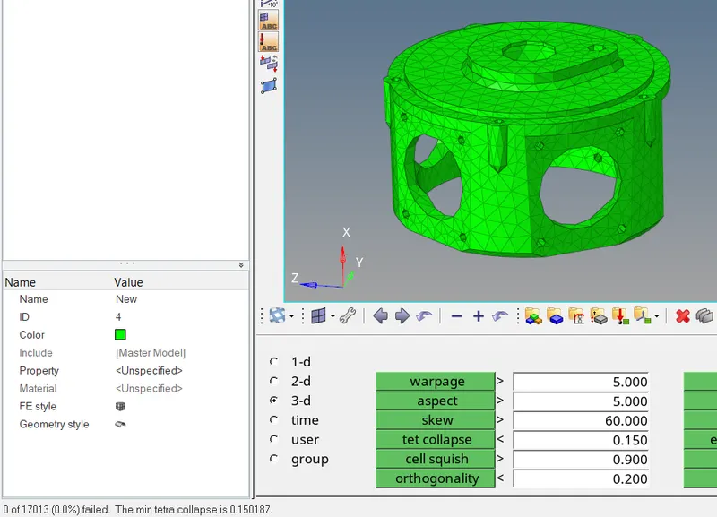
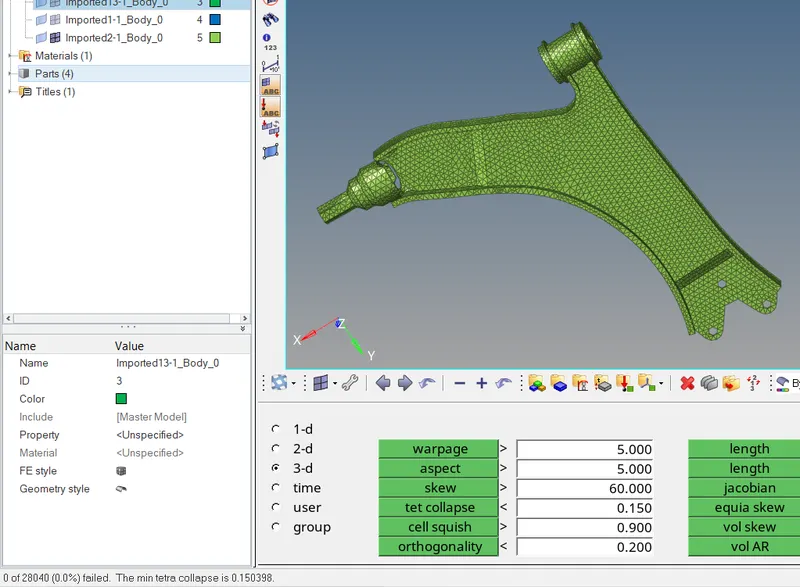
5) For checking the tet collapse, we need to select the "check element" panel under the "Tools" option. Put the minimum tet collapse value and finding no of elements gets fail of total no of elements through the status bar.
6) If the elements are failing or not satifying the given minimum tet collapse value, remeshing the failed elements repetitively untill a failed elements will be satisfied.
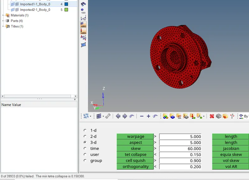
7) After complete few remeshing operation on this component, we get a proper elements without failing due to minimum tet collapse parameters.
Model 3
Steps to 3d meshing and removing tet collapse issue :
1) In model 3 we have consist of four components, perform a meshing operation on one by one component in same manner with that subsequently checking the minimum tet collapse parameters.
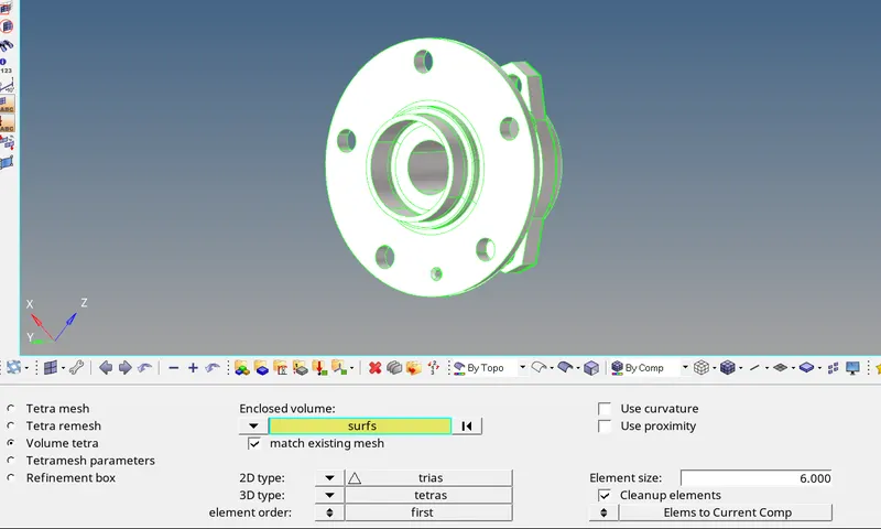
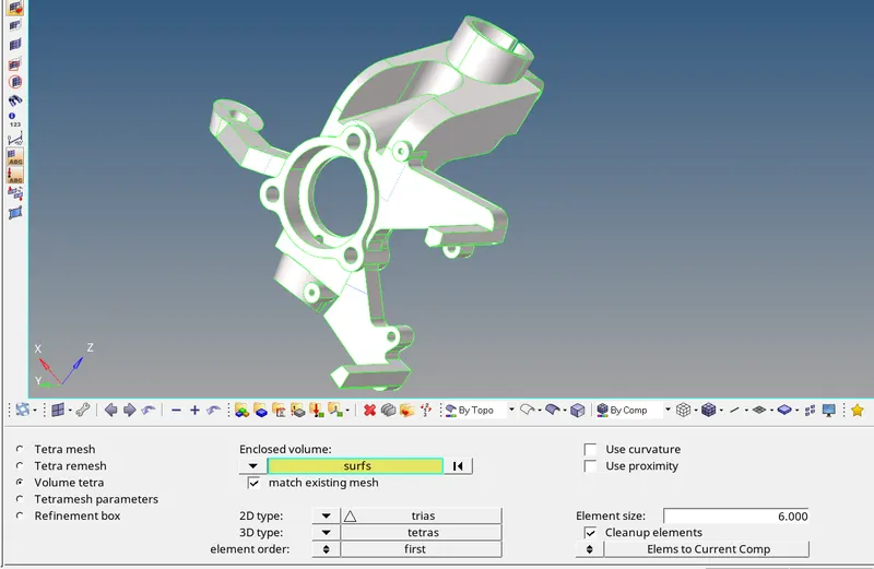
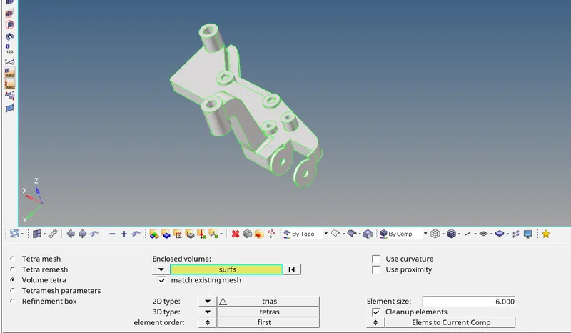
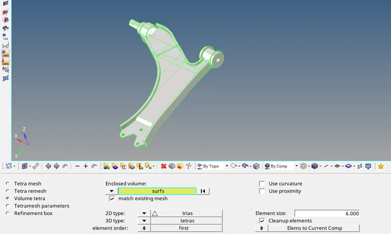
2) First of all, go to the "Volume tetra" sub panel under the "tetramesh" panel, choose the surface instead of solid. Click the particular component surface, it will automatically selected the all surfaces from the particular component. Set the element size which is 6mm and also check the cleanup elements option.
3) Go to "Tetramesh Parameters" for which give the minimum tet collapse value to all components.
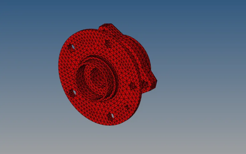
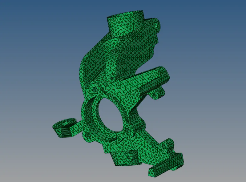
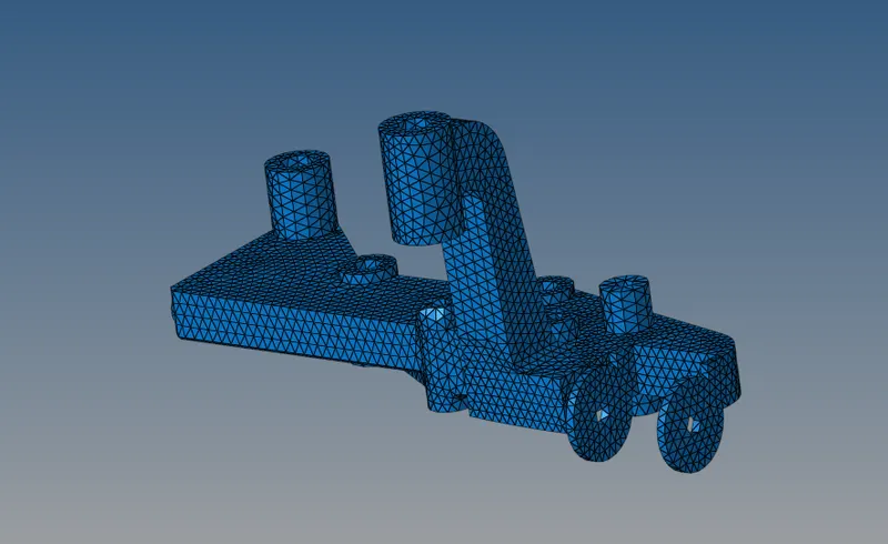
4) Again comes to "Volume tetra" option and then click to mesh. After that, 3d tetrahedral elements are generated for that particular component.
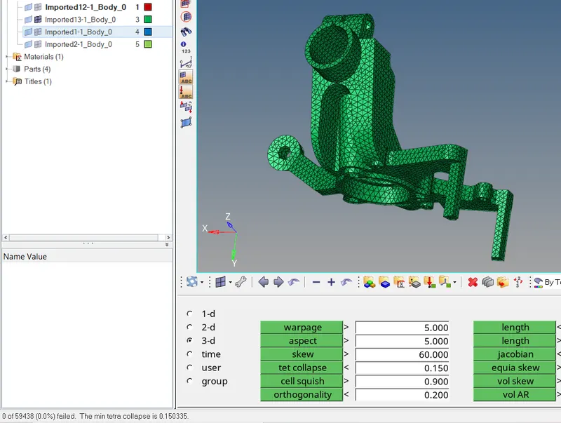
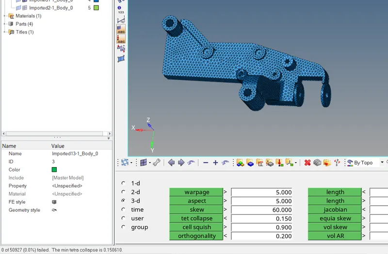
5) Go to "Check element" panel under the "Tools" option, click the 'tet collapse' parameter and view the no of elements are failure due to minimum tet collapse from the status bar.
6) By using "Tetra remesh" option to repetitivity remeshing on that particular failure elements untill gets zero failure.
7) These steps are followed to all components.
Component 1
Component 2
Component 3 :
Component 4
CONCLUSION :
1) Successfully to created the 2d trias shell elements on a model 1 components and also passed the minimum and maximum element length quality parameters. After which, successfully created the 3D tetrahedral element by the reference of 2d trias elements.
2) To Created the 3d tetrahedral elements on model 2 & 3 components and also passed the minimum tet collapse parametrs.