Week 8 - Challenge 1 - Draft Analysis on a Fan Cover
Draft Analysis on a Fan Cover
Aim:
To Create the tooling axis for the given Fan cover model meeting the requirements of the draft angle and perform the Draft analysis on the model.
What is draft:
A draft angle is a slant that is applied to each side of most features of an injection molded part. The angle, which is positioned to run toward the direction of a mold's pull and parting line, helps with releasing the part from the mold.
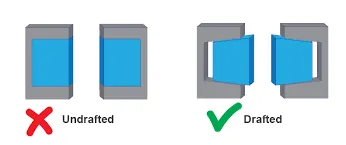
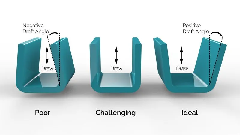
Without it, parts run the risk of poor cosmetic finishes, and may bend, break, or warp due to molding stresses caused by the plastic cooling. Equally important, an absence of draft may prevent parts from ejecting from the mold, damaging not only the parts, but possibly the mold itself—a costly and time-consuming detour.
DRAFT ANALYSIS:
The Draft Analysis command enables you to detect if the part you drafted will be easily removed. This type of analysis is performed based on color ranges identifying zones on the analyzed element where the deviation from the draft direction at any point, corresponds to specified values.
PROCEDURE:
TOOLING AXIS:
The machining process instantiation supports the absolute or relative coordinates for tool axis and machining directions.
Tool axis — Select to define the tool orientation. The default value is Vertical, which is used for standard 3-axis machining. However, it can also be a fixed angle or a continuously changing orientation.
1.First step is to open the given fan cover class A surface in catia software.
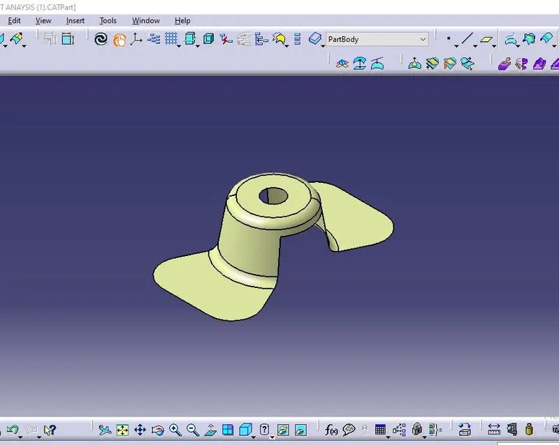
2.After importing the model to check the boundaries,to check the any gap is there between the given class A surface or not.
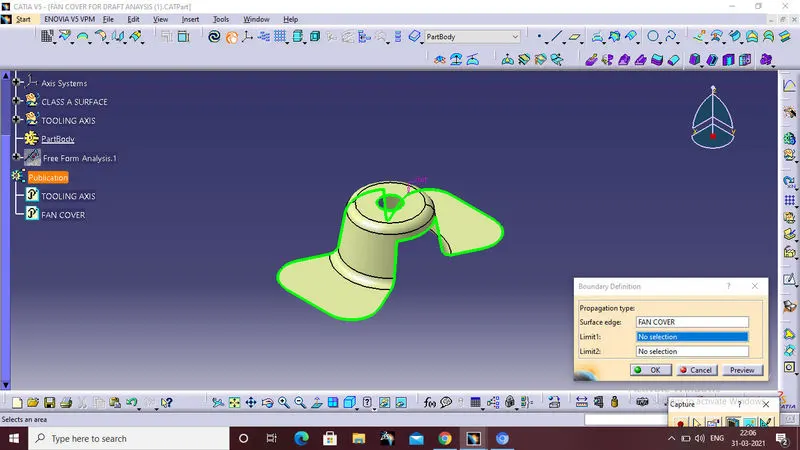
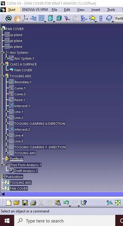
3.In order to craete a tooling axis, first create the dummy tooling axis in the Z-direction.
To create the tooling axis in X-direction, first insert the point at the center of the hole on the class A surface.
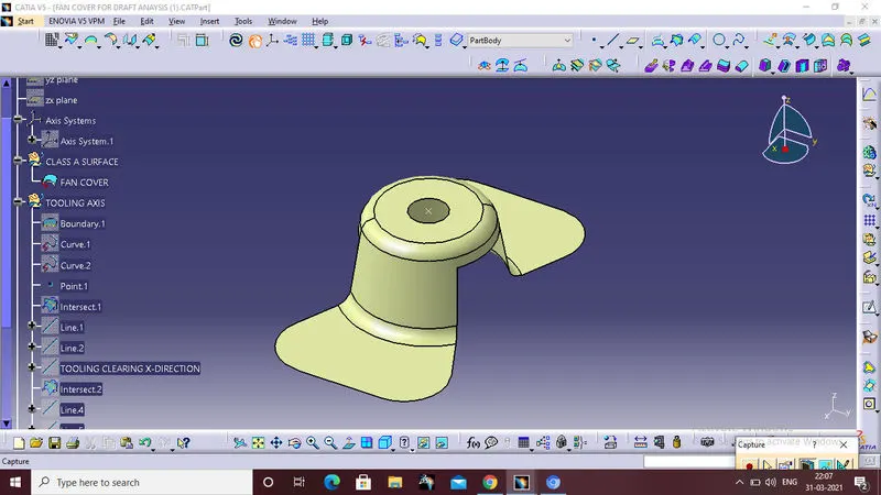
4.After insert the point to create the new axis system at the center point of the hole, the position of x,y,z of the new axis system and the vehicle axis system also in same direction.
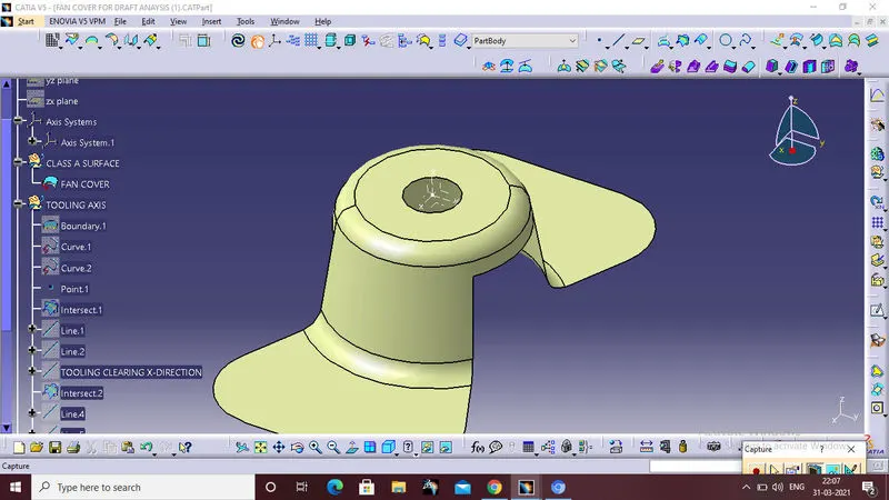
5.Now use the intersection command,intersect the ZX plane of the axis system and the given fan cover(class A surface).This will give the 2d drawing of the fan cover viewing from the x-direction.
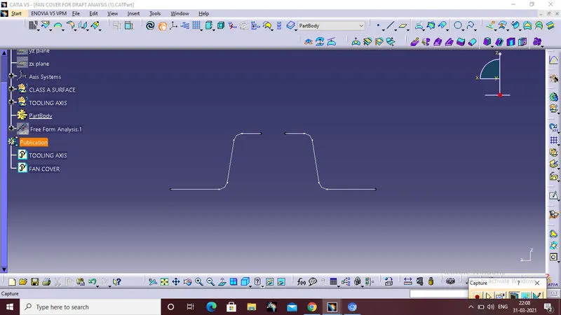
6.Then create the line by using point to point option,that line reptresents the x side wall of the fan cover.opposite side also create line by using same method by the use of intersect.
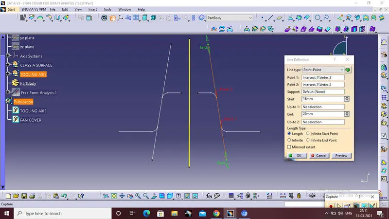
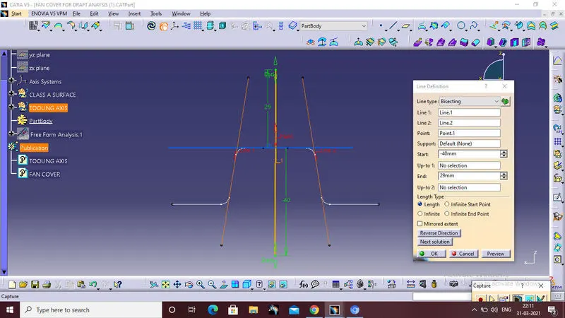
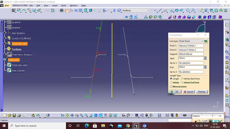 by the use of this two lines to cteate the tooling clearing in x-direction,by using the bisecting line command in line option.To bisect the last two lines with the reference point in the z- direction that will form the tool clearing in x-direction.
7.Similarly by using the intersect opition in yz plane of the axis system to fan cover to get the tool clearing in y-direction.follow the same method used for x-direction
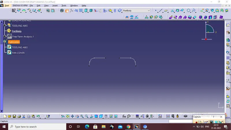
create the lines for y side walls
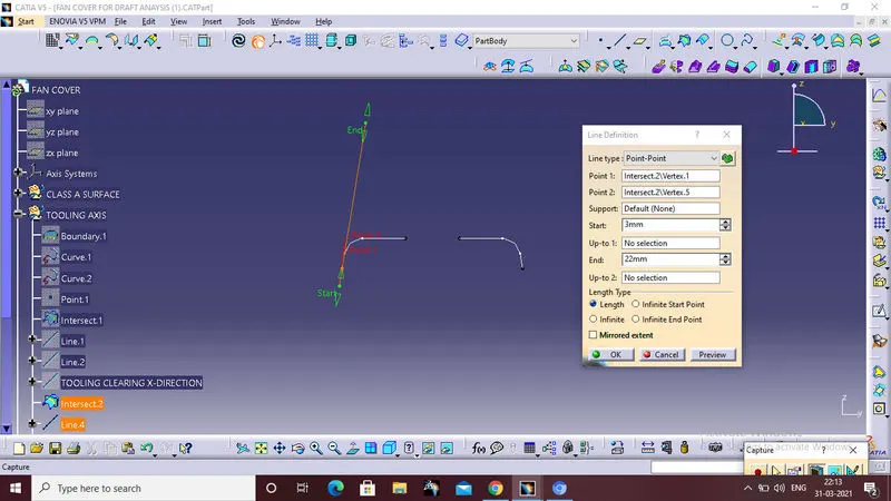
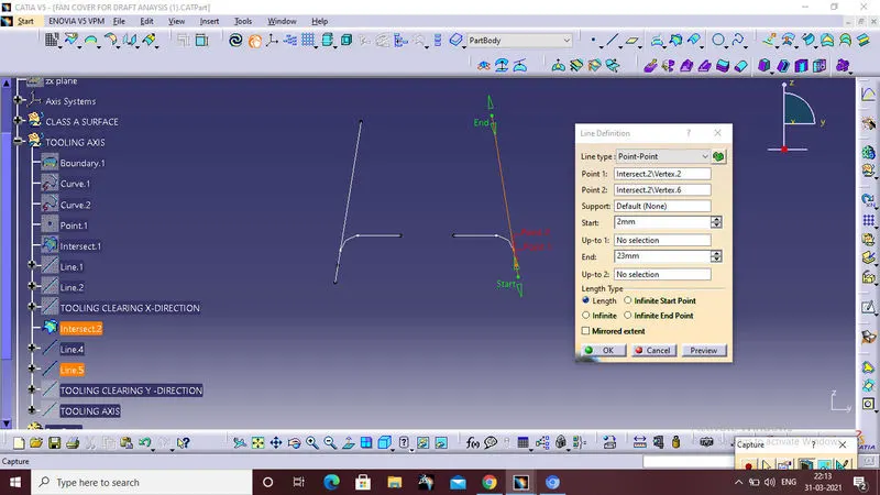
bisecting the last two line with the reference point this will form the tool clearing in y-direction.
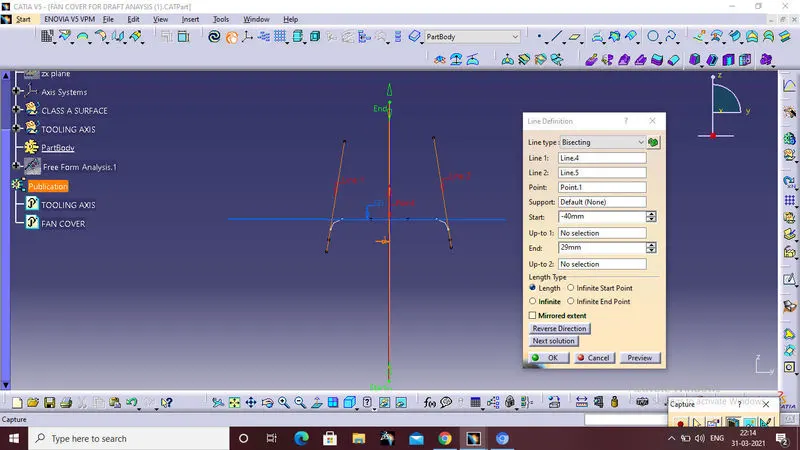
8.Once x axis and y axis are formed,To bisecting the x and y tooling line with the reference point that will form the tool clearing in z-direction.That is the final tooling axis for fan cover 9class A surface)
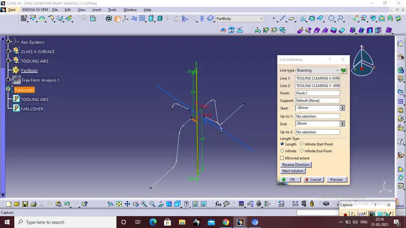
Draft analysis in Catia V5:
- enter part in Catia.
- Go to Material Mode.
- 03.go for draft analysis.
- drag axis bar to the tooling direction of part.
- check for draft and make parting line as per analysis.
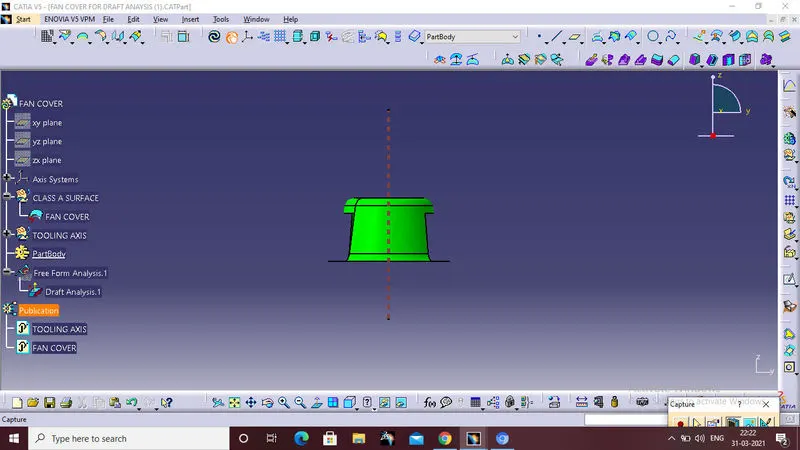
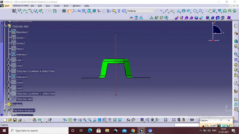
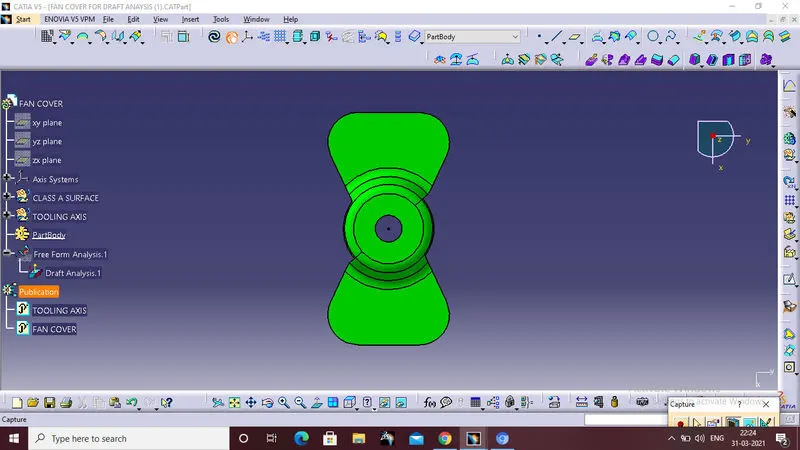
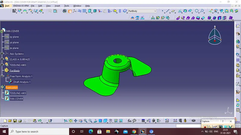
First step is to give the draft direction,for that use the compass and align the z-axis of it with the tooling axis which we created for the model.once the tooling axis is properly alinged,locked the direction.A samll red colour pointer is shown on the screen,just click anywhere on the class A surface and it will shows the current draft angle of the given model.set the draft value at 3deg under the colour scale variant and clik ok.After finishing the all of the settings click ok on the draft analysis table.
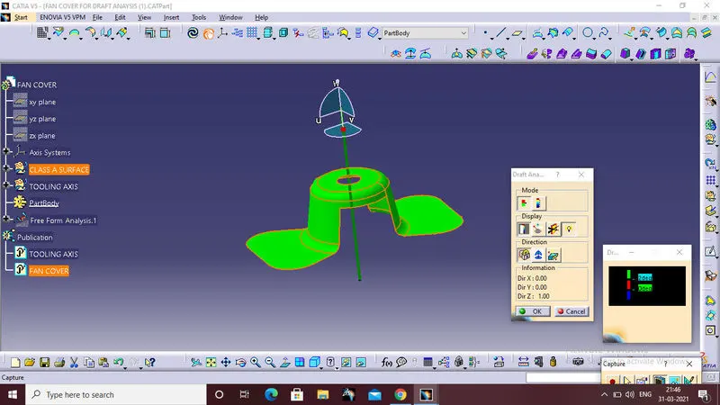
To publish the tooling axis and the fan cover, first select the tooling axis and fan cover from the geometric set and go to Menu bar>Tools>Publication.This will publish the tooling axis and fan surface.Published items will coming out from the geometrical set.
VIEWS:
FRONT VIEW:
SIDE VIEW:
TOP VIEW:
ISOMETRIC VIEW:
TREE STRUCTURE:
CONCLUSION:
- A detailed report should be done explaining the draft analysis and the tooling axis creation.
- An explanation should be given on the way of creating the tooling axis particularly the Bisecting method.
- Screenshots of the Draft analysis report.
- Image of the complete Draft analysis.
- Images of the color scale variant .
- Screenshots of the model with the proper color code of the draft angle in various orientations (Isometric, Front, Side, and Top View.
- CATpart should be submitted as an attachment using the below Browse option.
Above all process are sucessfully completed and submitted by using the catia software.