Week 8 - Challenge 1 - Base Bracket Design
Aim :- To design the Base Bracket plastic component through the given Class-A surface.
Objective :-
- To create a proper tooling direction.
- To perform draft analysis of the plastic component.
- To design the base bracket plastic component by creating the B-Surface and C-Surface using the given Class-A surface.
Tooling Direction :-
Tooling axis is the direction in which mold or core and cavity opens. The ejection of the part from mold depends on the draft. A zero draft can result in difficult or no ejection due to shrinkage. It is recommended to add a minimum of 0.5 to 1 degree of the draft for non-textured surface & 3 to 5 degree of draft for textured surfaces.
Procedure to create the tooling axis using bisecting method :-
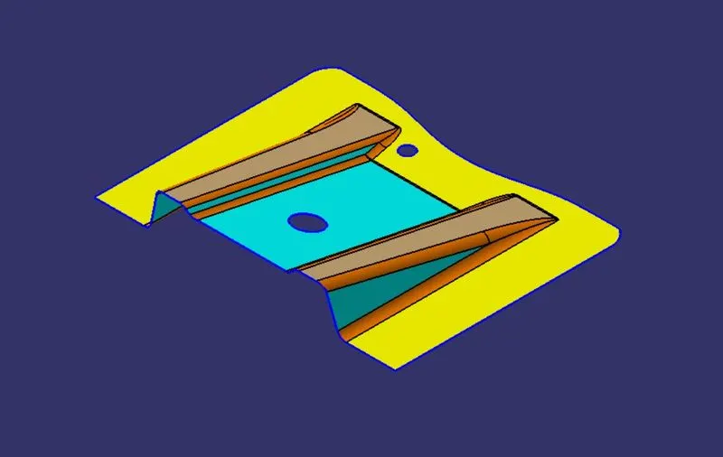
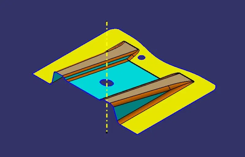
Following Class A surface is provided to design the base bracket plastic component.
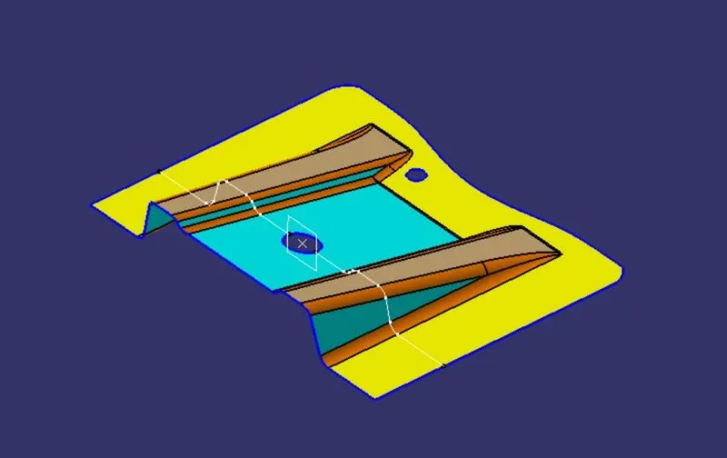
YZ Plane is created at the center of the hole and intersection of a surface is taken along the created plane.
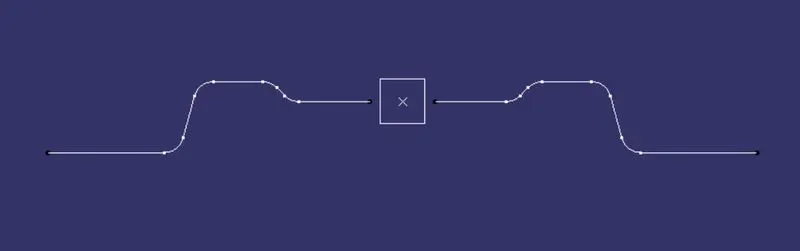
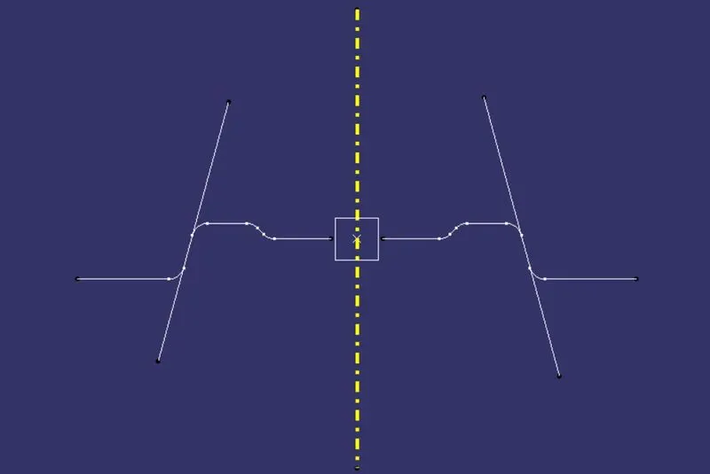
Lines are drawn to the side faces of the intersected curves then bisecting line is created between these two lines.
Final Tooling Axis with A-Surface.
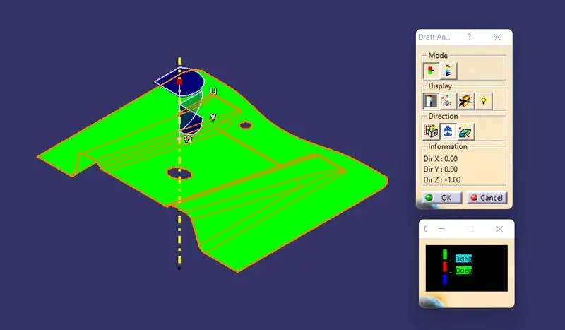
Draft analysis :-
Draft analysis is performed based on color ranges identifying zones on the analyzed element where the deviation from the draft direction at any point, corresponds to specified values. Minimum draft angle is considered as 3 degree.
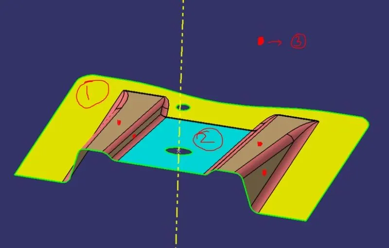
CLASS B SURFACE:
We can divide the surfaces as shown below. Then we will work on them one by one.
FLAT SURFACE:
- Extract the flat surface.
- Un-trim the surface.
- Extrapolate it.
- Offset it by 2.5mm i.e. thickness.
SLANT SURFACE:
- Extract the slant surface.
- Un-trim the surface.
- Extrapolate it.
- Offset it by 2.5mm i.e. thickness.
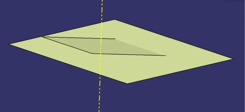
RIBS SURFACES:
- Extract the rib surfaces (1 rib at a time).
- Un-trim the surface.
- Extrapolate it.
- Offset it by 2.5mm i.e. thickness.
- Trim to get the desired shape.
- Repeat it with the second rib too.
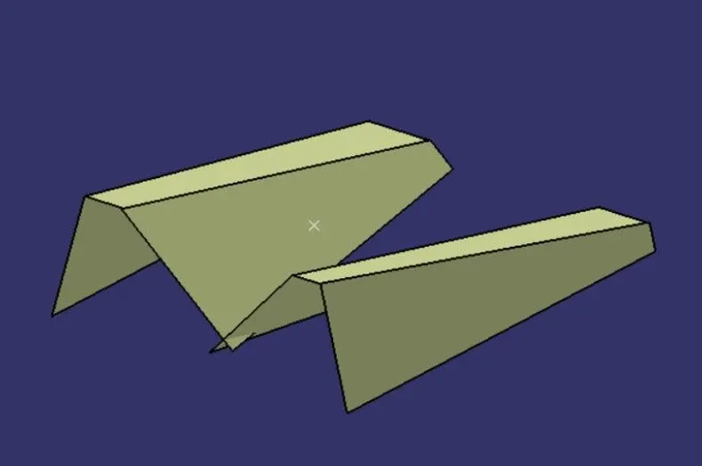
Once we have finished doing this, we have to trim the surface to get exact shape of the class-A surface (without fillet) below 2.5mm. After the trimming part is done, fillet the model. Formula for filleting= fillet value+thickness (if the surface is below). We get our class-B surface.
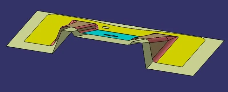
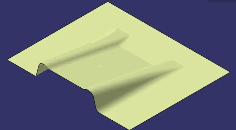
FOR CLASS-C SURFACE:
- Extract the boundary of the class-A surface.
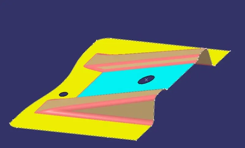
2.Extract the boundary of the holes on the class-A surface.
3.Use sweep command on the boundaries one by one to get the class-C surface.
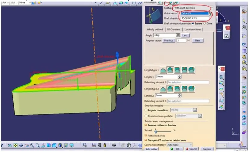
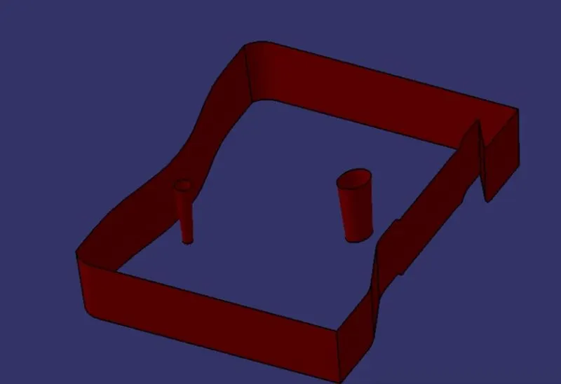
FINAL BASE BRACKET:
- Join the class-A and class-C surfaces together.
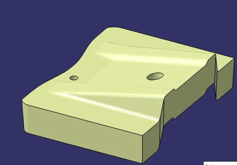
2.Trim the class-B surface with the join created earlier.
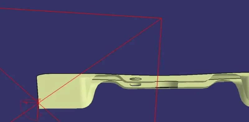
3. Final B-Surface.
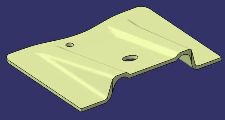
Go to Part Design and Close the model.
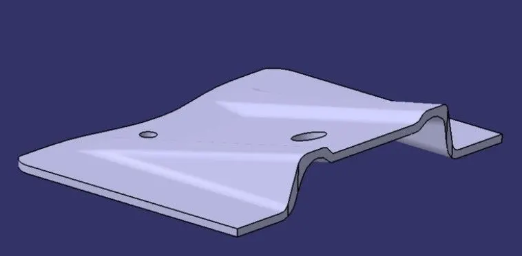
FRONT VIEW :-
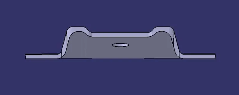
TOP VIEW :-
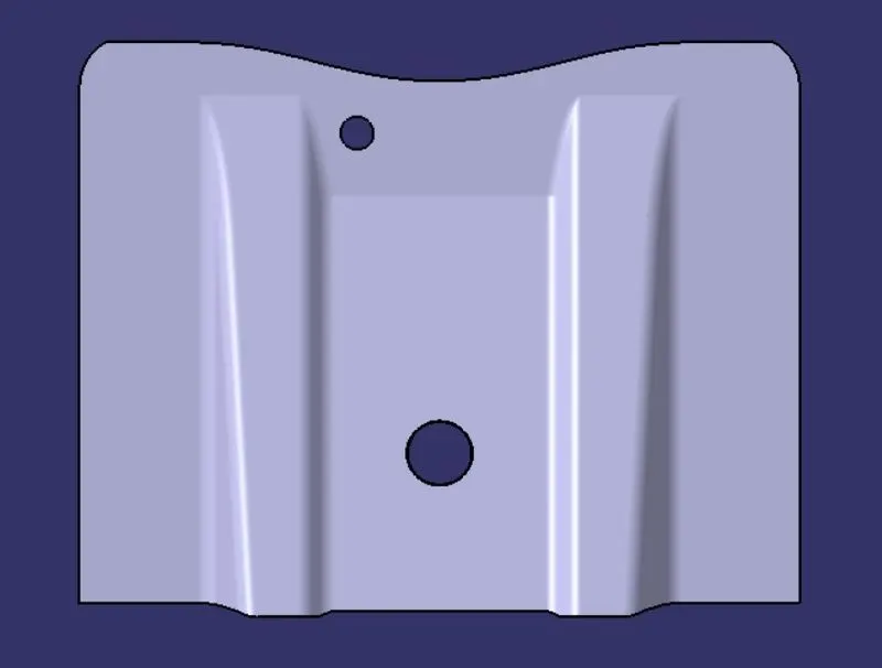
SIDE VIEW :-
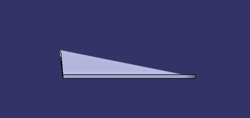
ISOMETRIC VIEW :-
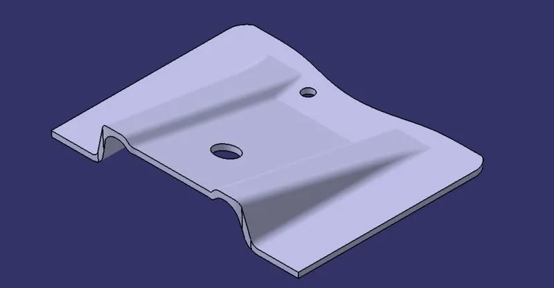
TREE STRUCTURE :-

Conclusion :-
Thus the base bracket plastic component has been designed using the given class-A surface.