Week 8 - Challenge 1 - Base Bracket Design
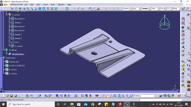
AIM: Create the Base Bracket Plastic component through the given Class-A surface. To begin with, the tooling axis for the given Class-A Surface should be created meeting the requirements of the draft angle and at the end perform the Draft analysis on the model.
GIVEN CLASS A SURFACE:
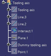
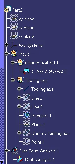
Tree structure for creating Toolng Axis
PROCEDURE:
A) TOOLING AXIS CREATION:
- Create a point on class A surface with the aim to move the main tool for component creation.
- Mask an axis over the point created with the same directions as the main axis.

- Using Intersect command from Generative Shape design select the YZ plane as the first element and the class A surface as the second element.

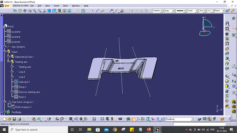
- After creating the intersecting lines select the Line command and join the vertices which show the most possible draft angle manufacturable and bisect those two lines over the axis point we selected at the first.

Tool axis creation
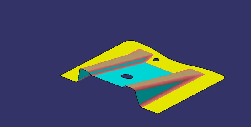
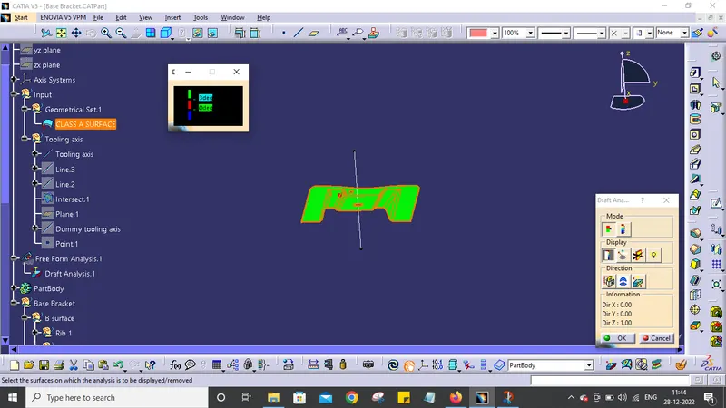
Draft Analysis
PROCEDURE for Draft Analysis of Class A Surface:
- After Tooling Axis Select the Feature Draft Analysis option from the Insert Option.

- Select the element to analyze.
- Next click on Use the compass to define the new current draft direction option and make it align with the tooling axis by dragging it to the axis.

- If the color appears blue just click the invert option on the right side of the draft direction axis button.
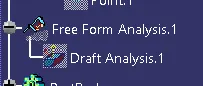
Tree structure for Draft Analysis
Draft Analysis
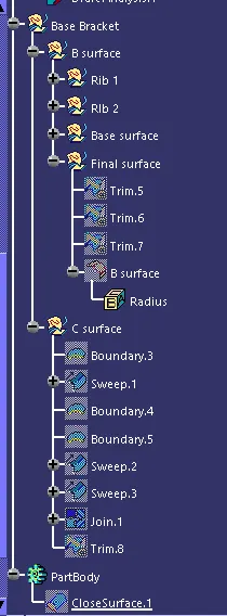
Complete Tree Structure
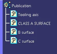
Use of Pulication Command
Isometric view