Week 8:Centrifugal pump simulation
Week 8:Centrifugal pump simulation
Introduction:
- Centrifugal pump is a mechanical device which is designed to move a fluid.
- The movement of fluid takes place by means of rotational force of the impellars.
- The fluid enters along the axis of the rotational impellar. The impellar increases the velocity and pressure of the working fluid and it pumps out through the outlet.
Aim:
To Run 3 cases with following outflow mass flow rate.
- 130 kg/s
- 156 kg/s
- 180 kg/s
Geometry:
- Imported a given Centrifugal pump model into Converge Studio.
- CAD clean up was performed.
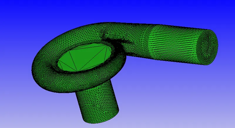
- Mesh details:
dx = 12e-3m, dy = 12e-3m & dz = 12e-3m
Case Setup:
- Application: General Flow
- Solver: Transient solver
- Simulation Type: Liquid
- Material: Air
- Species: H2O
- Simulation mode: Full hydrodynamic
- Simulation time parameters:
Start time:0 sec
End time:0.2 sec - Region & Initialization:
Created a region for initializing the setup - Boundary conditions
Inlet - Inflow - Pressure - 101325 pa and Temperature 300k
Outlet - Outflow
1.130kg/s
2.156kg/s
3.180 kg/s
Volute - Wall
Shroud - Wall
Impellar Rotating wall -12000deg/s along z axis
Intake runner - Wall - Turbulence Model - K epsilon
- The time interval for writing 3D output data files: 0.002 sec
- The time interval for writing text output:1e-6 sec
- The time interval for writing restarting output:0.001sec
- Maximum number of restart file saved:3
Results -
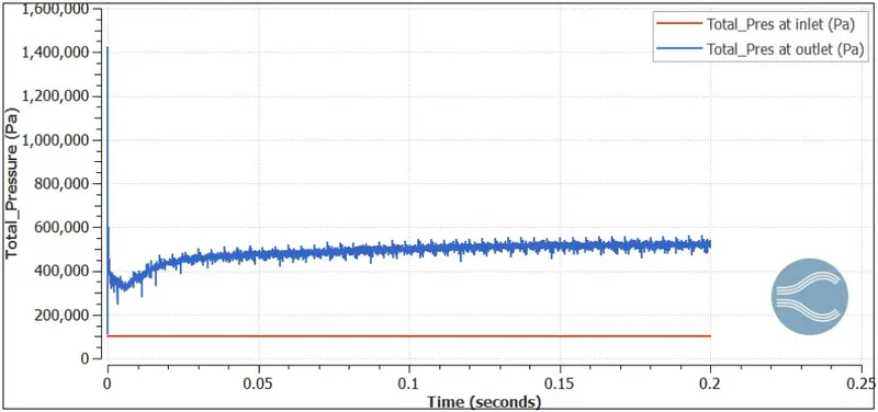
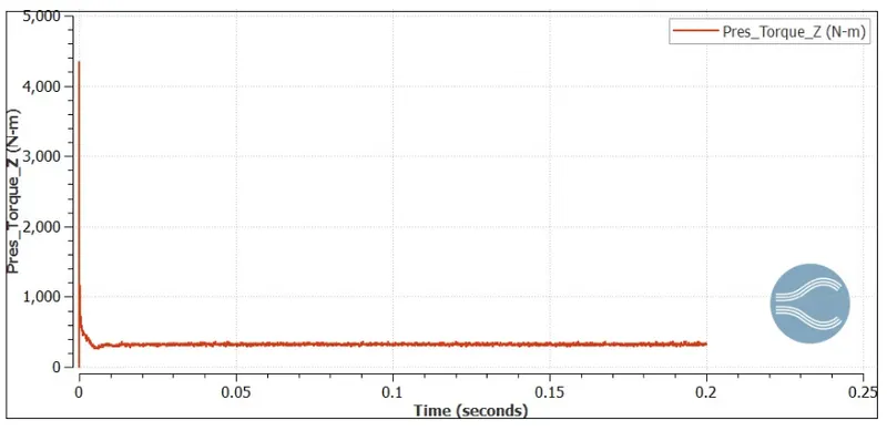
1. Massflow rate - 130kg/s
- Total Pressure:
- Torque :
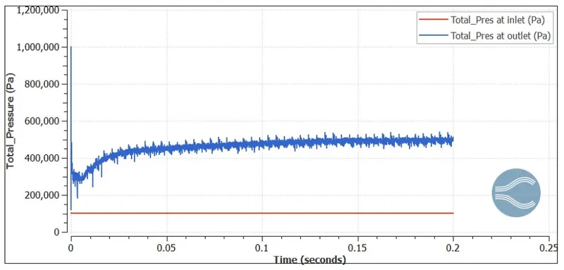
2. Mass flow rate 156 kg/s
- Total Pressure :
- Torque:
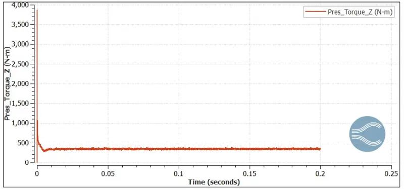
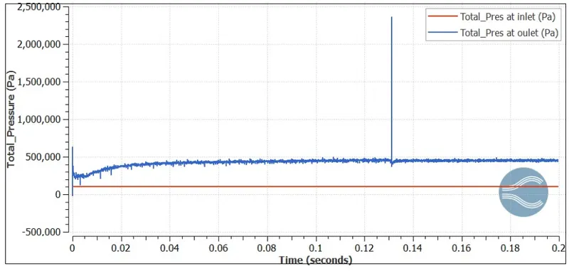
3.Mass flow rate 180kg/s:
- Total Pressure:
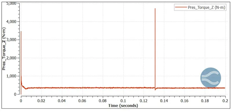
- Torque:
Pressure ratio vs Mass flow rate:
| Mass flow rate | Total Pressure at Inlet | Total Pressure at outlet | Pressure ratio |
| 130 |
101325 |
546337 | 5.3919 |
| 156 | 101325 | 501658 | 4.9509 |
| 180 | 101325 | 451714 | 4.4580 |
Efficiency :
Pump efficiency: It is defined as the ratio of the power output of the pump to the power input to the pump.
η=(ρ×g×Q×Hm)/(Pshaft×1000)
Pshaft=(2π×N×T)/60
| Mass flow rate (kg/s) | Torque | Impellar speed | Shaft Power |
| 130 | 312 | 2000 | 65.94 |
| 156 | 346 | 2000 | 72.42 |
| 180 | 360 | 2000 | 75.38 |
| Mass flow rate (kg/s) | Mass flow rate in m3/s | Pressure head (m) | Hydraulic power (Kw) | Shaft power (Kw) | Pump efficiency |
| 130 | 0.13 | 45.63 | 58.18 | 65.94 | 88.24 |
| 156 | 0.156 | 40.8 | 64.42 | 72.42 | 89.41 |
| 180 | 0.18 | 35.71 | 67.254 | 75.38 | 83.65 |
Conclusion:
Simulation in Centrifugal pump with different mass flow rate was performed.