BlockMesh Drill down challenge
AIM:
To mesh the geometry by changing the BlockMeshDict file and simulate a 2D flow through a Backward Facing step using OpenFOAM.
Mesh specification
- Number of cells along the x direction = 200
- Number of cells along the y direction = 10
- Provide a grading factor = 0.2 as Case 2.
Procedure:
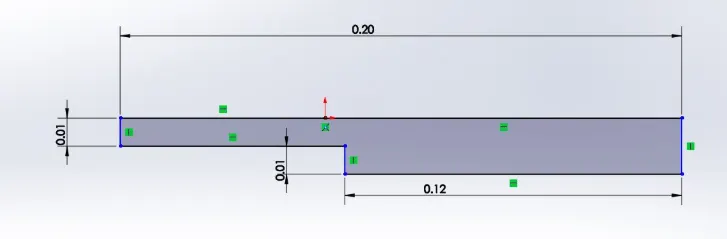
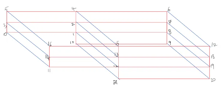
1. The below geometry is divided into 5 blocks as shown below and the vertices are indexed.
2. "tutorial/incompressible/icoFoam/cavity" directory is copied into $FOAM_RUN. In the terminal type in 'run' command to go to $FOAM_RUN and rename the recently copied file.
3.Edit the BlockMeshDict file as shown below
BlockMeshDict file
/*--------------------------------*- C++ -*----------------------------------*
  =========                 |
  \      /  F ield         | OpenFOAM: The Open Source CFD Toolbox
   \    /   O peration     | Website:  https://openfoam.org
    \  /    A nd           | Version:  8
     \/     M anipulation  |
*---------------------------------------------------------------------------*/
FoamFile
{
    version     2.0;
    format      ascii;
    class       dictionary;
    object      blockMeshDict;
}
// * * * * * * * * * * * * * * * * * * * * * * * * * * * * * * * * * * * * * //

convertToMeters 1;

vertices
(
    (0 0 0)		//0
    (0.08 0 0)		//1
    (0.08 0.005 0)	//2
    (0 0.005 0)		//3
    (0.08 0.01 0)	//4
    (0 0.01 0)		//5
    (0.2 0.01 0)	//6
    (0.2 0.005 0)	//7
    (0.2 0 0)		//8
    (0.2 -0.01 0)	//9
    (0.08 -0.01 0)	//10
    (0 0 0.001)		//11
    (0.08 0 0.001)	//12
    (0.08 0.005 0.001)	//13
    (0 0.005 0.001)	//14
    (0.08 0.01 0.001)	//15
    (0 0.01 0.001)	//16
    (0.2 0.01 0.001)	//17
    (0.2 0.005 0.001)	//18
    (0.2 0 0.001)	//19
    (0.2 -0.01 0.001)	//20
    (0.08 -0.01 0.001)	//21
);

blocks
(
    hex (0 1 2 3 11 12 13 14) (200 20 1) simpleGrading (1 1 1)
    hex (3 2 4 5 14 13 15 16) (200 20 1) simpleGrading (1 1 1)
    hex (2 7 6 4 13 18 17 15) (200 20 1) simpleGrading (1 1 1)
    hex (1 8 7 2 12 19 18 13) (200 20 1) simpleGrading (1 1 1)
    hex (10 9 8 1 21 20 19 12) (200 20 1) simpleGrading (1 1 1)
);

edges
(
);

boundary
(
    topAndBottom
    {
        type wall;
        faces
        (
            (4 5 16 15)
            (6 4 15 17)
	    (0 1 12 11)
            (10 9 20 21)
        );
    }
    stepWall
    {
        type wall;
        faces
        (
            (1 10 21 12)
        );
    }
    frontAndBack
    {
        type empty;
        faces
        (
            (11 12 13 14)
            (14 13 15 16)
            (13 18 17 15)
            (12 19 18 13)
            (21 20 19 12)
	    (3 2 1 0)
            (5 4 2 3)
            (4 6 7 2)
            (2 7 8 1)
            (1 8 9 10)
        );
    }
    inlet
    {
       type patch;
        faces
        (
            (0 11 14 3)
            (3 14 16 5)
        );
    }
    outlet
    {
        type patch;
        faces
        (
            (20 9 8 19)
            (19 8 7 18)
            (18 7 6 17)
        );
    }
);

mergePatchPairs
(
);

// ************************************************************************* //
4. The pressure and velocity boundary conditions are provided by changing the values in the 'p' and 'U' files in the '0' directory as shown below
/*--------------------------------*- C++ -*----------------------------------*
  =========                 |
  \      /  F ield         | OpenFOAM: The Open Source CFD Toolbox
   \    /   O peration     | Website:  https://openfoam.org
    \  /    A nd           | Version:  8
     \/     M anipulation  |
*---------------------------------------------------------------------------*/
FoamFile
{
    version     2.0;
    format      ascii;
    class       volScalarField;
    object      p;
}
// * * * * * * * * * * * * * * * * * * * * * * * * * * * * * * * * * * * * * //

dimensions      [0 2 -2 0 0 0 0];

internalField   uniform 0;

boundaryField
{
    inlet
    {
        type            zeroGradient;
    }

    outlet
    {
        type            fixedValue;
	value		uniform 0;
    }
    topAndBottom
    {
        type            zeroGradient;
    }
    stepWall
    {
        type            zeroGradient;
    }

    frontAndBack
    {
        type            empty;
    }
}

// ************************************************************************* //
/*--------------------------------*- C++ -*----------------------------------*
========= |
\ / F ield | OpenFOAM: The Open Source CFD Toolbox
\ / O peration | Website: https://openfoam.org
\ / A nd | Version: 8
\/ M anipulation |
*---------------------------------------------------------------------------*/
FoamFile
{
version 2.0;
format ascii;
class volVectorField;
object U;
}
// * * * * * * * * * * * * * * * * * * * * * * * * * * * * * * * * * * * * * //
dimensions [0 1 -1 0 0 0 0];
internalField uniform (0 0 0);
boundaryField
{
outlet
{
type zeroGradient;
}
inlet
{
type fixedValue;
value uniform (1 0 0);
}
topAndBottom
{
type noSlip;
}
stepWall
{
type noSlip;
}
frontAndBack
{
type empty;
}
}
// ************************************************************************* //5. The control card for the simulation is changed as shown below to use a time step = 0.0001 and end time =1s.
/*--------------------------------*- C++ -*----------------------------------*
  =========                 |
  \      /  F ield         | OpenFOAM: The Open Source CFD Toolbox
   \    /   O peration     | Website:  https://openfoam.org
    \  /    A nd           | Version:  8
     \/     M anipulation  |
*---------------------------------------------------------------------------*/
FoamFile
{
    version     2.0;
    format      ascii;
    class       dictionary;
    location    "system";
    object      controlDict;
}
// * * * * * * * * * * * * * * * * * * * * * * * * * * * * * * * * * * * * * //

application     icoFoam;

startFrom       startTime;

startTime       0;

stopAt          endTime;

endTime         1;

deltaT          0.00001;

writeControl    timeStep;

writeInterval   10000;

purgeWrite      0;

writeFormat     ascii;

writePrecision  6;

writeCompression off;

timeFormat      general;

timePrecision   6;

runTimeModifiable true;


// ************************************************************************* //
6.'blockMesh' code is run in terminal to convert the inputted values iin blockMeshDict file to an usable meshed geometry which is available in polyMesh directory
7. The solver as we know is icoFoam. So by ussing 'icoFoam' code in terminal the above simulation is run till desired time.
8. 'ParaFoam' command is used to open paraView which is utilized for plotting the required results as follows.
Results:
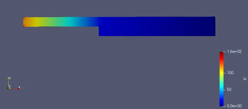
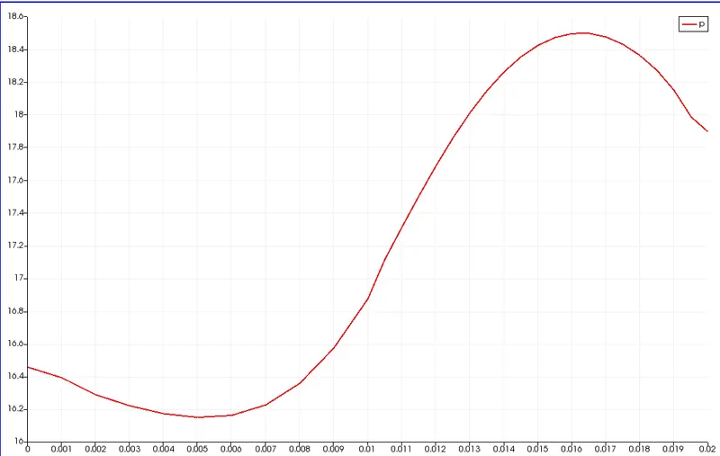
Grading = 1
Velocity contour
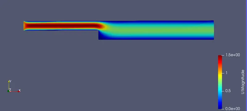
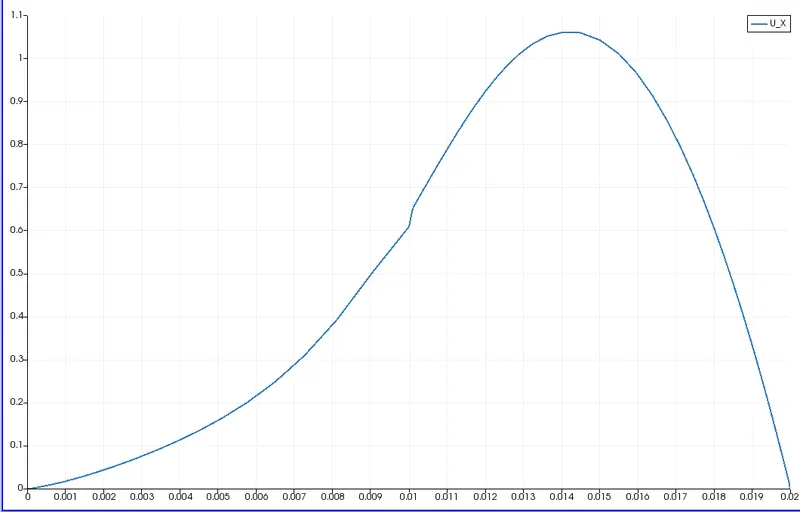
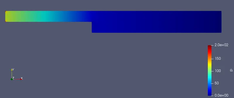
Since the meshing used is a simple grading the velocity values obtained near to the wall may not be accurate.
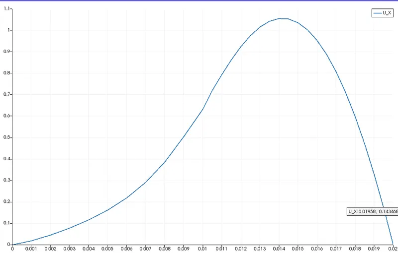
Pressure contour
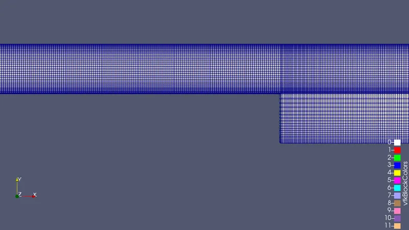
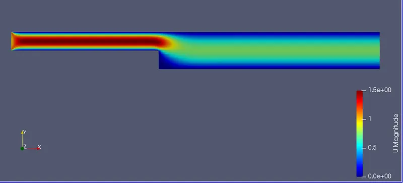
Grading = 0.2
blocks
(
    hex (0 1 2 3 11 12 13 14) (200 20 1) simpleGrading (1 5 1)
    hex (3 2 4 5 14 13 15 16) (200 20 1) simpleGrading (1 0.2 1)
    hex (2 7 6 4 13 18 17 15) (200 20 1) simpleGrading (5 0.2 1)
    hex (1 8 7 2 12 19 18 13) (200 20 1) simpleGrading (5 5 1)
    hex (10 9 8 1 21 20 19 12) (200 20 1) simpleGrading (5 5 1)
);
By utilizing above grading we can create a fine mesh near to the wall so that the velocity profile near to wall can be captured accurately. Main idea behing this is to study flow seperation if any in the step region.
CONCLUSION:
If higher velocity input is taken into consideration then providing a finer mesh will be useful to study the presence of vorticities near to the step. In the above case providing a fine mesh did not yield desired changes in the accuracy of the obtained results.
Understood the basic ideology in openFoam and how to utilize the tutorial section for further understanding of basic fluid flow principles.