Week 8-3D Tetra Meshing Challenge
AIM: - CREATE A 3D TETRAMESH OF THE GEOMETRIES ACCORDING TO THE GIVEN DETAILS.
Objectives:
1. Create tetra mesh for the Housing component by converting 2D mesh into 3D mesh with the following quality criteria:
Element Size: Min: 2 units; Target: 5 units; Max: 7 units.
Tet Collapse: 0.15
2. Create a 3D tetra mesh of the given component using Quick Tetra Mesh/ Volume Tetra Mesh with the following Quality criteria:
Target Element Size: 3 units.
Tet Collapse: 0.15.
3. Create a 3D tetra mesh of the given component using Quick Tetra Mesh/ Volume Tetra Mesh with the following Quality criteria:
Target Element Size: 4 units.
Tet Collapse: 0.15.
The 3D tetra mesh of all the components was generated using Hypermesh and the profile used for the purpose was Optistruct.
Problem 1: Housing Model
The imported geometry of the given component in Hypermesh looks like this:
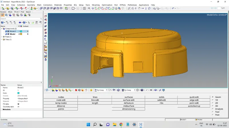
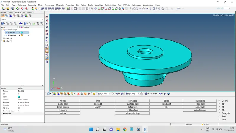
In this problem, first, a 2D tria mesh was developed having the same element size criteria as the tetra mesh. This 2D mesh was then converted into a 3D tetra mesh using the 3D mesh panel of Hypermesh.
So, to accomplish this, first, the given geometries were cleaned up to avoid the minimum element length error and have a good 2D mesh.
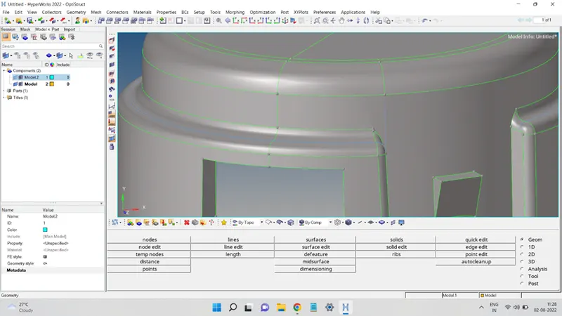
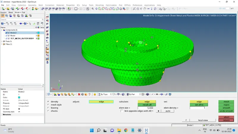
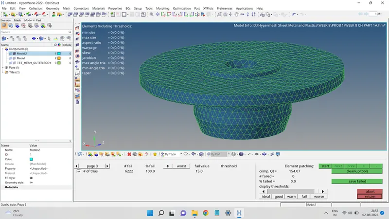
Next, the surface is then meshed using the Tria elements only. The mesh is then checked for the failing elements present and cleaned up to remove all those failing elements.
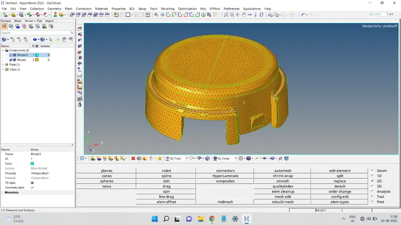
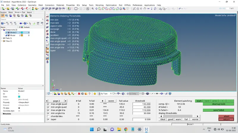
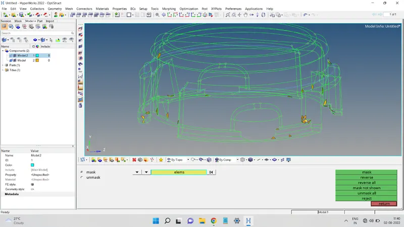
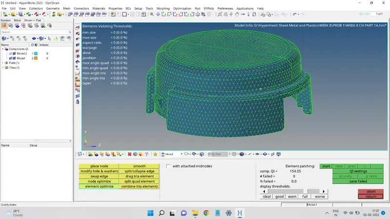
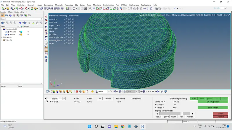
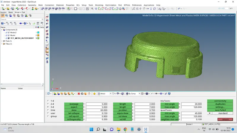
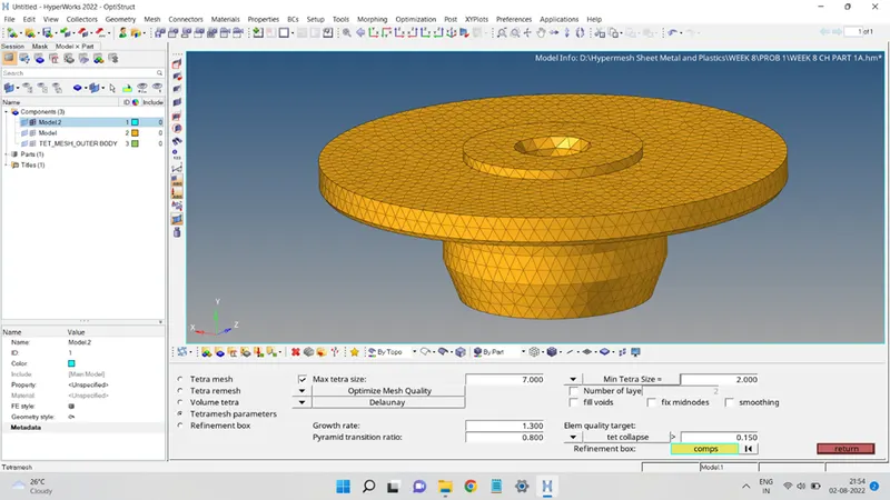
The 2D mesh was then converted into 3D Tetramesh using the 3D mesh panel and selecting the Tetra Mesh option. Selecting all the 2D elements and adding the quality criteria values. Finally, click on Mesh to obtain the 3D Tetra Mesh.
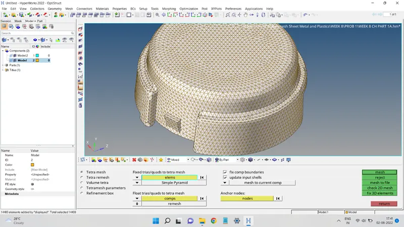
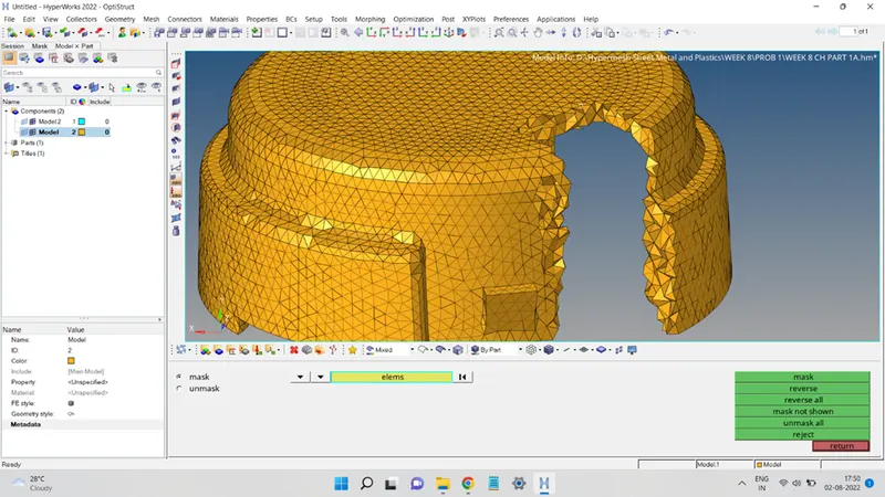
The quality of the mesh obtained can be seen in the figures below:
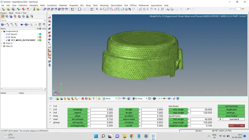
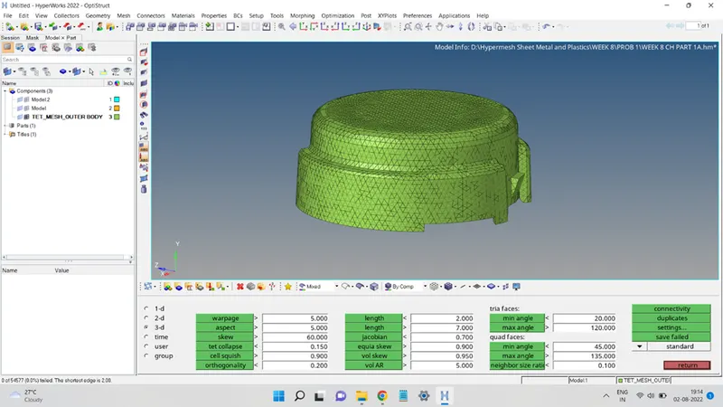
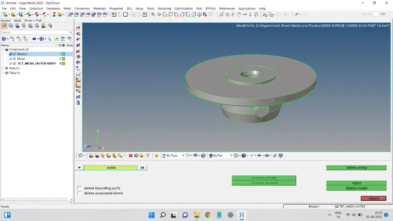
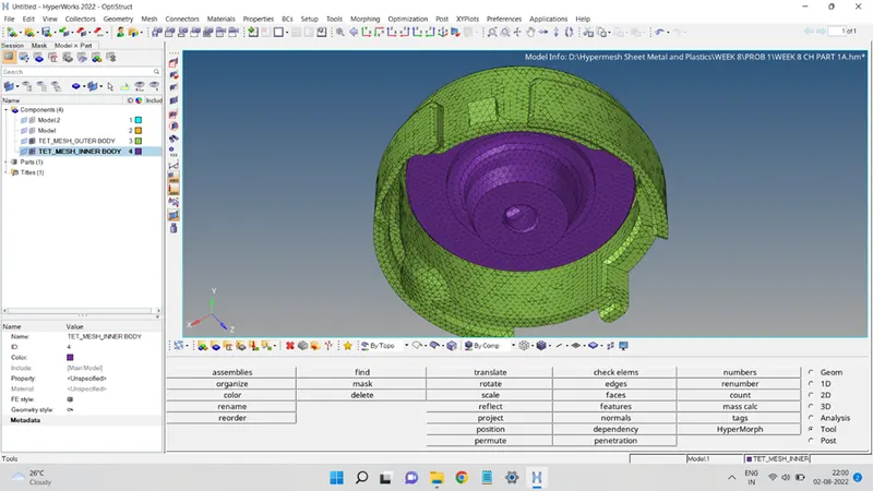
In the same way, the inner body of the geometry was also 3D meshed, as shown in the figures below:
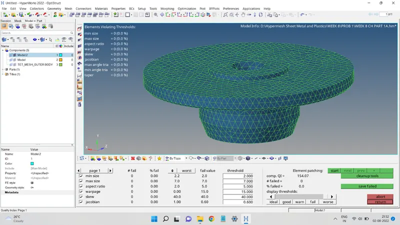
2D Tria Mesh and Quality:
Tetra Mesh:
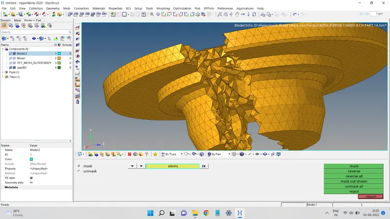
Mesh Quality:
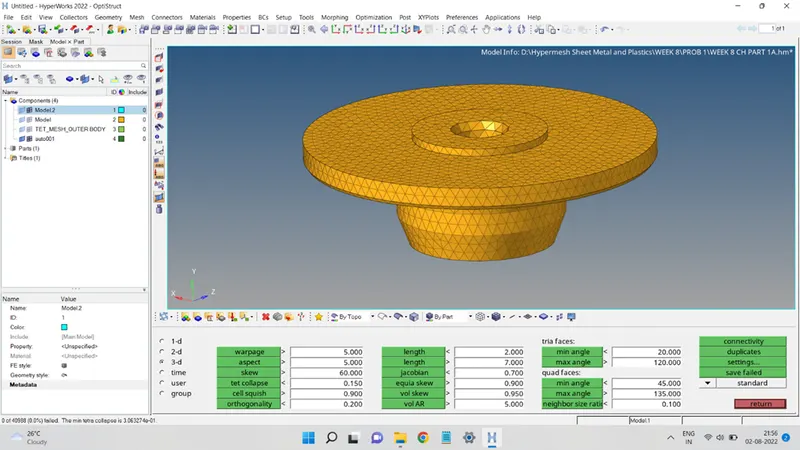
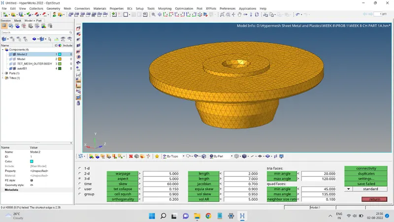

The final 3D Tetra Mesh of the given Housing model will look like this:
PROBLEM 2:
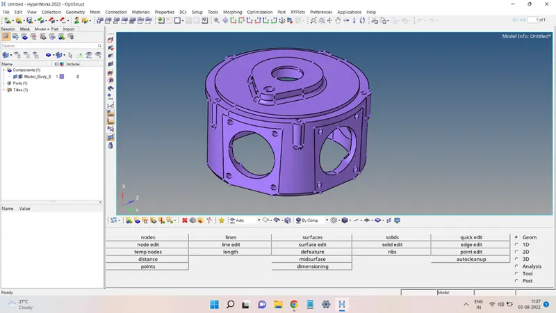
Import the given model geometry in the Hypermesh environment, the imported geometry will look like this:
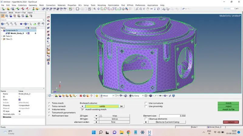
In this problem, the given solid geometry directly meshed into a 3D tetra mesh with the help of the Volume Tetra command present in the 3D panel.
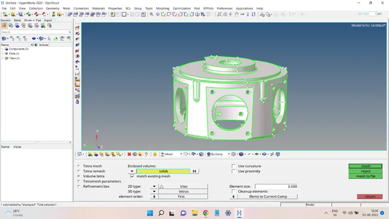
Select Solids as the entity for the Enclosed volume and then select the geometry. Enter the Element Size as 3 units. In 2d Type choose Trias and for Element order choose first. Click on Mesh to generate the mesh. The mesh obtained is:
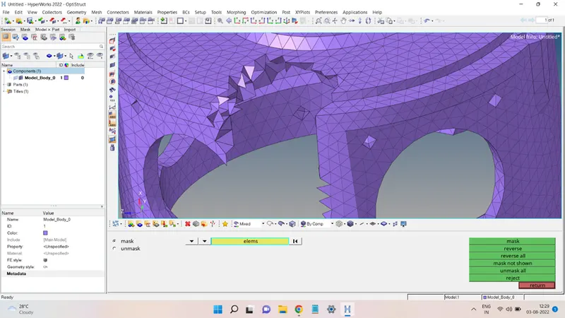
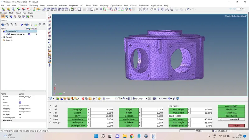
Few elements that were failing the quality criteria were brought within the quality tolerance and finally, the mesh looks like this:
PROBLEM 3: Turbocharger Model
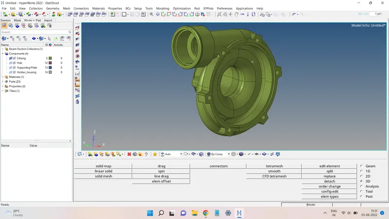
For this problem, the .hm file of the model was given and after loading the model, the geometry looked like this:
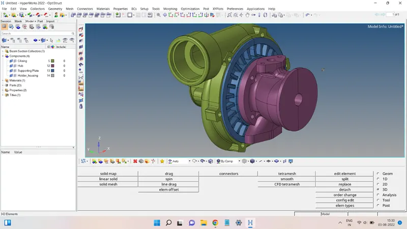
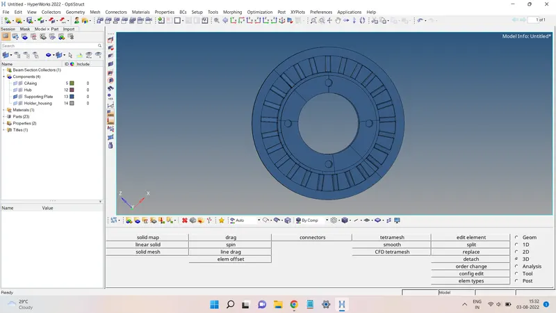
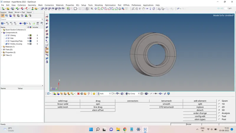
the model contained 4 different parts stored in four different components according to the names of the parts
1. Casing.
2. Hub.
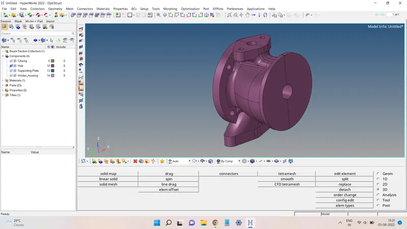
3. Supporting Plate.
4. Holder housing.
Each of the components was meshed directly into a 3D Tetra mesh using the Quick Tetra command present in the Geom/Mesh section of the Utility browser.
Before that, each component geometry was cleaned up in order to obtain a closed volume geometry surface body.
All the geometries were split into two parts and each part is closed using a surface. These surfaces were first deleted from each part and then both the parts were equivalenced to obtain a single closed volume body instead of the two.
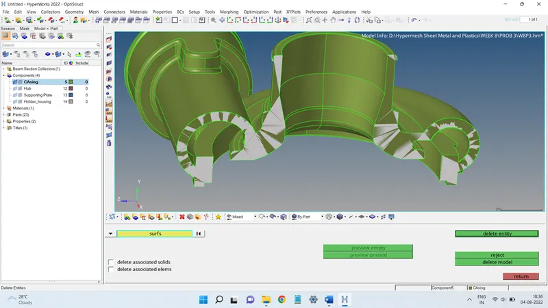
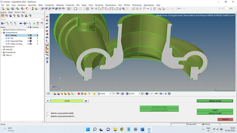
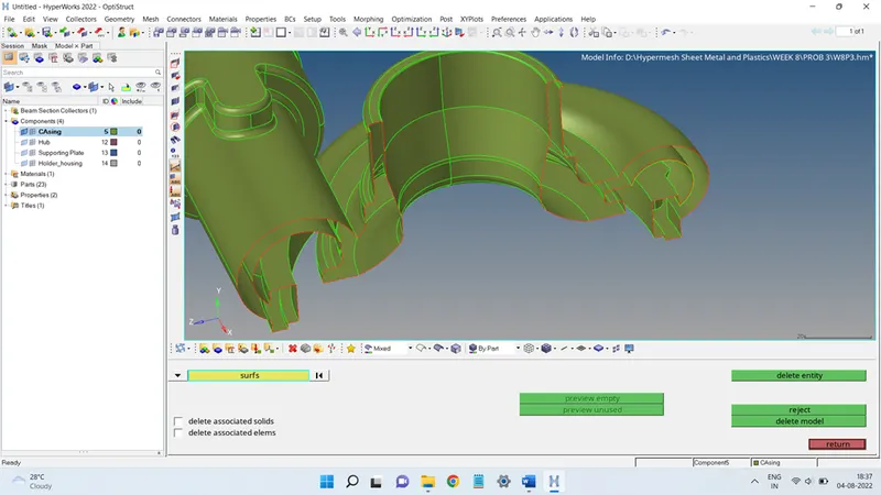
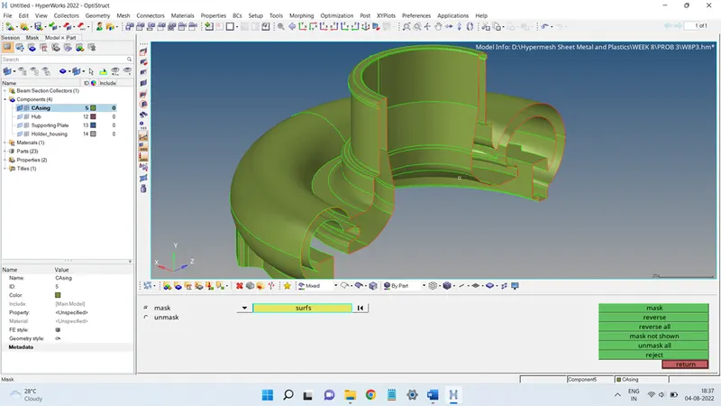
Now, these two parts will be joined together using the Equivalence command in the Edge Edit panel.
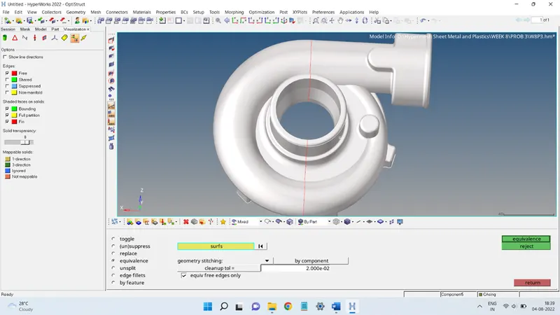
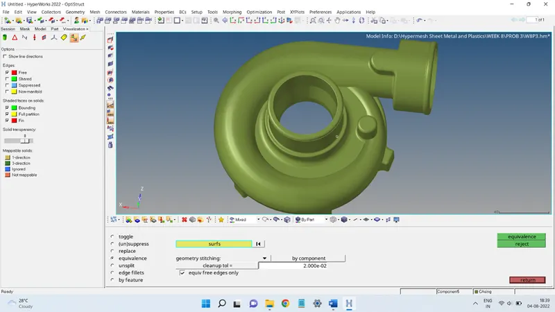
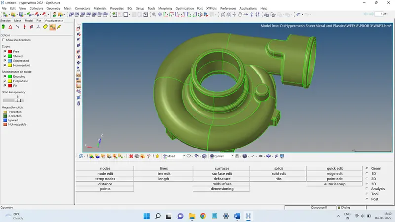
Next, all the unwanted shared edges were suppressed to avoid errors during the Quick Tetra meshing process.
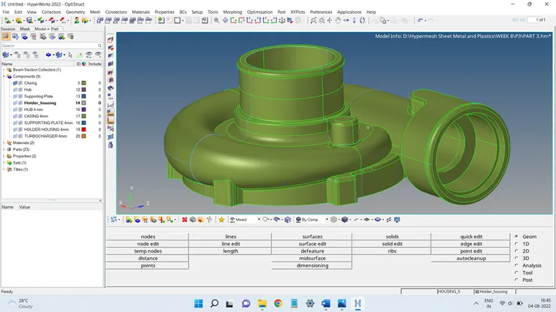
This was done as each part and then each part was meshed using the Quick Tetra.
To access the Quick Tetra panel, click on View and click o Browsers and select Hypermesh and then select Utility. In the Utility panel, go to the bottom right and click on Geom/Mesh, it will open up the Geom and Mesh panel. In the Mesh panel, select Quick Tetra to arrive at the Quick Tetra panel.
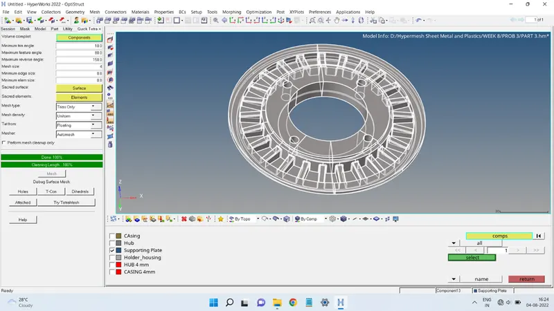
In the Quick Tetra panel, click on the Components icon to add the desired component to the Volume Complist, as shown below:
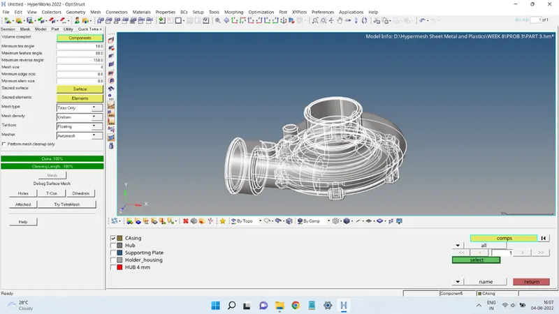
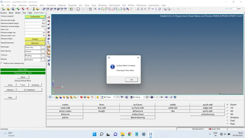
Mesh Size value is taken as 4 units and the rest parameters were taken as it is, since there was no data related to them. Click on the Mesh icon to begin the tetra mesh. On successful 3D meshing using this method, the Hypermesh will display a message as shown below:

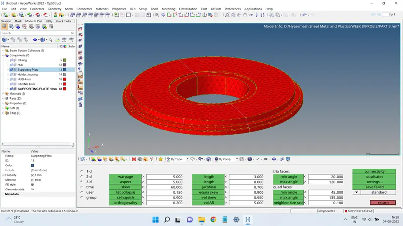
The mesh obtained will be saved in a separate collector named Quick_Tets.
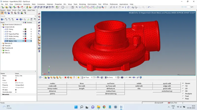
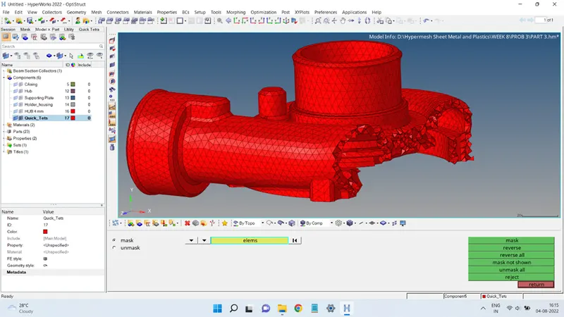
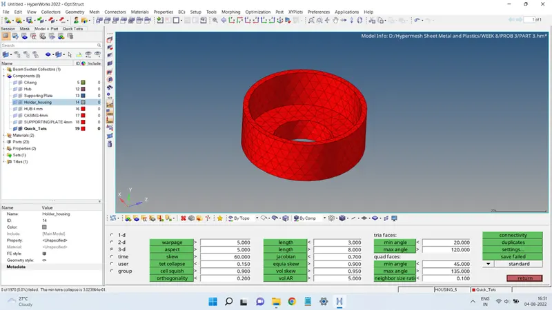
The Tet Collapse quality of the mesh is shown below:
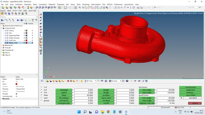
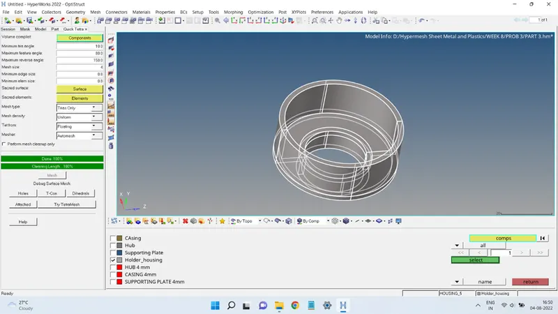
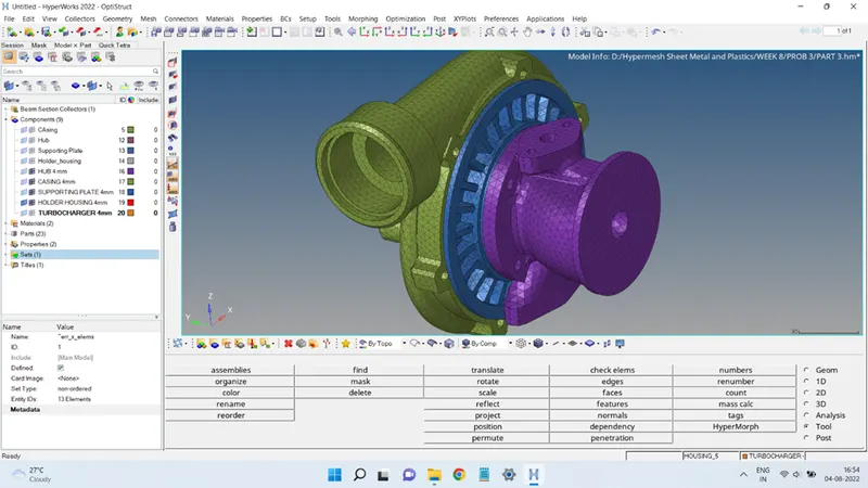
Through a similar process the other three parts of the geometry were also meshed, as shown below:
Finally, after meshing all four parts, the combined mesh will look like this:
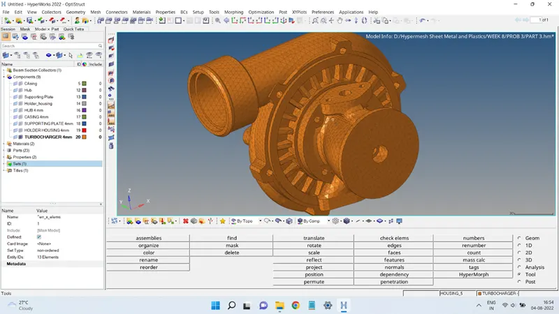
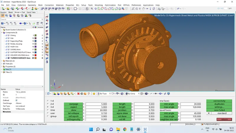
The combined mesh is saved in a separate collector named TURBOCHARGER 4mm, as shown below:
conclusion:
This exercise helped in learning about the different methods Hypermesh offers to obtain a 3D Tetra Mesh of any component.
It also gave the idea about different quality criteria involved in a 3D mesh and how the failing elements must be brought within the given quality tolerance.