Week 8-3D Tetra Meshing Challenge
3D Tetra Meshing Challenge
OBJECTIVE:
To pre-process the given model files and to generate volume mesh over the component using puerly tetra elements
PROCEDURE:
MODEL -1
Setting up model
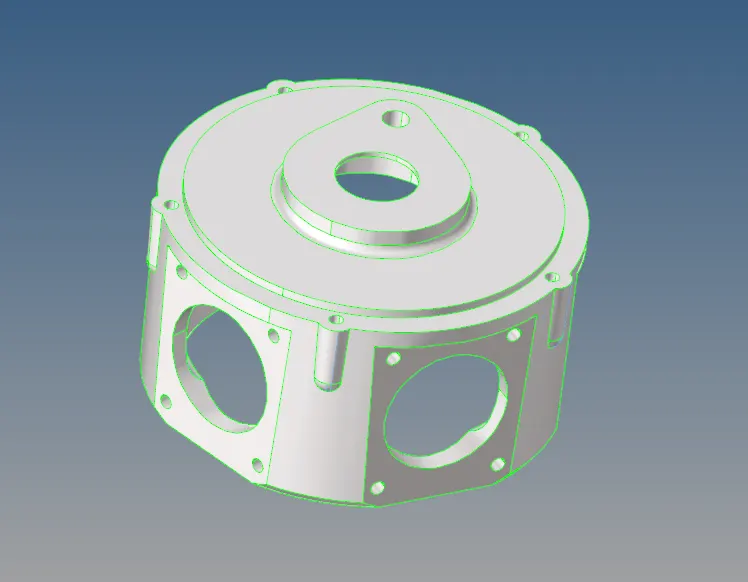
- The first model is of a housing component (as shown below)
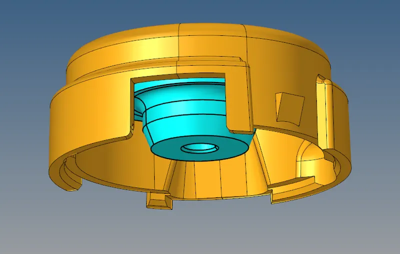
- Before generating a tetra mesh, the model has to be cleared for geometrical errors and meshed using 2D elements.
- Since tetras or volume mesh is generated by mapping trias over two opposite surfaces.
- For geometry cleanup - features are defeatured, small surface fillets are removed and if required washers are introduced.
- Prior to generating volume mesh, surface mesh has to be created.
- Puerly trias can be generated on the model however quads can also be preferred since these qeauds will be split into two trias and mapped for tetras during volume meshing.
Defeaturing
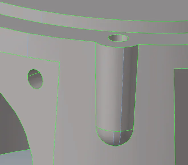
- Since the below feature has a distance of 1.3mm, this would fail for min quality length in the shell mesh element.
- Hence one side of the lines can be defeatured
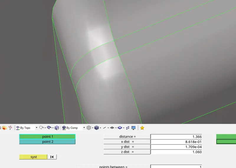
- Similarly other unrequired cons are defeatured using the toggle option.
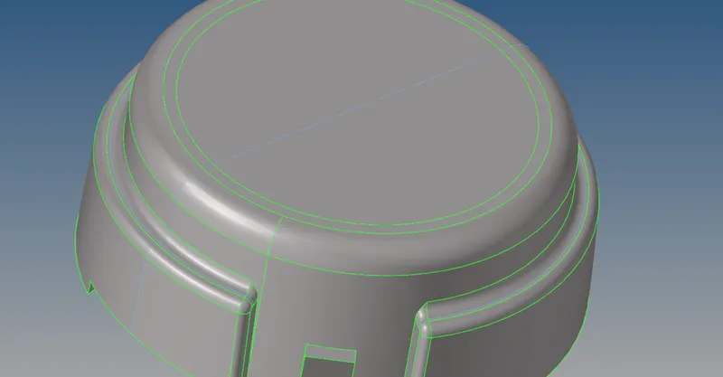
- Since in the end trias (unstructured mesh) are generated, having sectioning of the components arent required
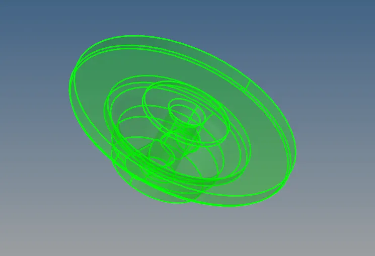
- One of the component in the model has a solid model.
- Solid models are redundant and can be deleted since shell elems can be generated over the surface
Shell meshing
- To generate shell elements:
- 2D - automesh - elem length = 5 - elem type = trias - 1st order - mesh
- The mesh is check for min and max length failure of below 2mm and above 7mm respectively.
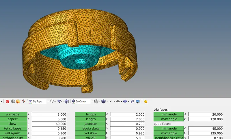
- Elements that fail quality can be cleared using cleanup tools in the quality tab or by remeshing the component.
- If elemets form at corners and fail for min length, these can be cleared by pasting nodes using the replace option (f3)
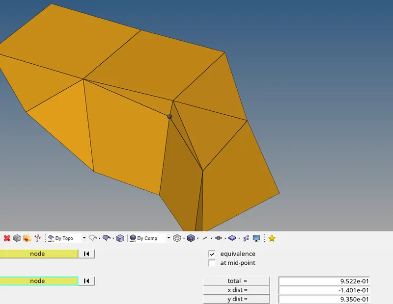
Volume mesh
- Volume mesh are generated by mapping opposite sides of the FE model and the corresponding elements.
- To generate a 3D mesh:
- 3D - tetramesh - specif parameters - mesh
- The two different initial ways to generate 3D elemens are using tetramesh and volume tetra.
- The tetramesh feature required a pre-existing 2D element for mapping. Alternatively can be generated diretly using the Utilities tab
- The volume tetra feature by default creates a shell mesh then generates the volume mesh
- In tetramesh the elemns of the 2D mesh elems are selected and split quads into trias is selected rather than generating pyramid elements.
- NOTE: Before generating the 3D elems of a certain comp make sure that comp is set as current
- Finally the component and the tetras can be visualized by masking few elements at the outer side.
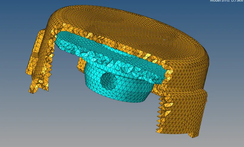
Tet-collapse
- Similarly as done for shell mesh, the 3D elems are also check for quality.
- The most commonly used parameter for tetra quality check is tet-collapse.
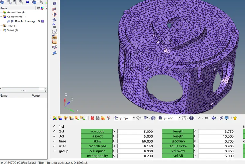
- It checks how far the elem deviates from being perfectly ideal or tetra. This means the every node must be equidistant from each other to be ideal. However a tolerance of 0.15 is set. The elem nodes shouldnt go below this level.
- To rectify this either the failed elems can be masked and remeshed using tetra remesh or maually rectified by setting the distance between each element.
MODEL -2
- This component is similarly defeatured at the begining then later meshed directly by volume tetra option.
- Unlike the tetramesh command, the volume tetra feature generates a surface mesh first and then maps those elements to generate the tetras all at one shot.
Defeaturing
- Features that have free edge at shared edges can either be equivalenced by selecting adjacent surfaces or Toggled on the free edge line (as shown below)
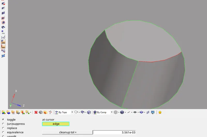
- Or the entire surface comp can be equivalence at one go by setting up a nominal tolerance limit
- And as usual, cons are defeatured using either the toggle or supress command
Volume meshing
- Unlike the previous method, in this case, the model is meshed directly under the 3D tab
- The volume tetra feature under 3D - tetramesh is used.
- The tetcollapse value is also set above 0.15 in the tetramesh parameters module
- To generate a volume tetramesh, the surface of the component can be used.
- Puerly trias or mixed elem type can be selected for 2D elem type since the quads can be seperated into two trias.
- A target length of 3mm is specified. The generated mesh is shown below
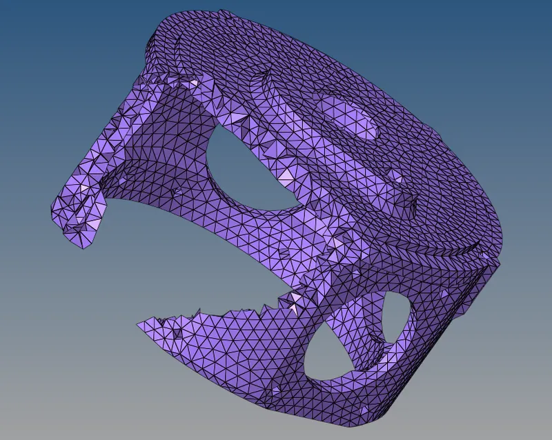
- Of the 3 elements that failed the tet value of 0.15 can be rectified either by remeshing with adjacent elems or can be pasted to nearby node
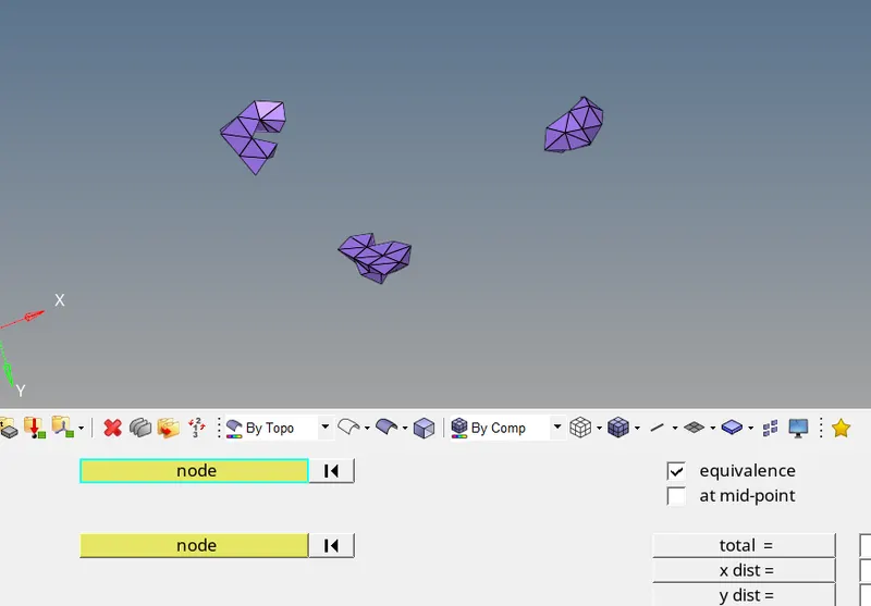
- If all elements are cleared for quality criteria the result would show as 0 in the check elems module in Tools (as shown below)
MODEL -3
Geometry cleanup & Defeaturing
- This is a casing model which is symmetrical about the central axis yet oriented at a different angle. Hence the generated 3D elems cannot be reflected.
- To cleanup the geometry, the solids in the model are initially removed.
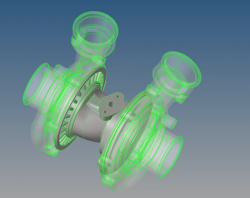
- Every component is masked and each is cleared for geometrical errors and defeaturing individually and meshed individually.
- Since the geometry is very complex with lot of feature lines, it is best to clean the model using autocleanup method and then manually check for any errors.
- For autocleanup, make sure the mid-surf extraction and create mesh option are checked off and only clean geometry is checked on.
- Similarly the 2nd layer of washer is eliminated in Holes 2D module.
Volume meshing
- This model unlike the other two is meshed using different method.
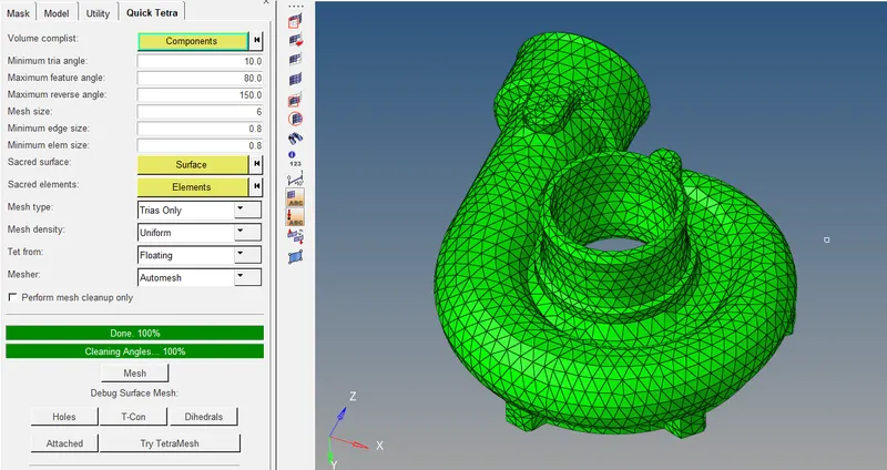
- On the utilities tab, Geom/mesh is selected from which tetramesh can be generated on any model with prior meshing using 2D elements.
- In the mesh tab, the component is selected and other parameters incl. target length (6mm) is specified. Also the element order and mesh type (trias only) are also specified.
- The resultant mesh is shown below
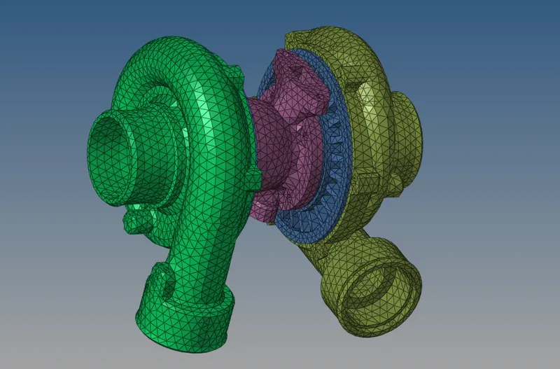
- Similarly every other components are meshed and the 3D elemes are added to each respective collector
- The final meshed model is shown below
CONCLUSION:
Hence all three components have been meshed using unstructed tetra 3D elements and checked for tet-collapse and refined accordingly.