Week 8:- 3D Finishing - Challenges 1
1. 3D FINISH PROCESS
3D Finishing is nothing but, delivering the final model of the design, which was conceptualized during the initial stage, complying to all the parameters, maintaining to the basic design intent.
The model made based on the initial design concept, should first proceed with the selection of materials for each and individual sub-parts, which all in together forms a particular assembly. There are various types of materials, which have different mass properties.
Any sub-part of a model assembly is converted into 3D form, by providing the right inputs, which we get from the 2D part drawing of the particular part. Measuring and analyzing the different geometrical sections of a 2D part drawing, helps to create the right 3D-model. Once we create the 3D-model in the tooling software, then we have to measure the same geometric sections on the created 3D model, by using the measuring instruments available in that software. If any discrepancy, found the respective modifications / alterations has to be done on the model.
Detailing of the final created 3D model, plays a crucial role for the completion of the 3D-design process. The Detailing mainly includes, the color codification for the respective sub-parts of an assembly, Providing the fillets and chamfer to the edges of the parts, Aligning the two parts in same direction / position, as called in the drawing and many more detailing aspects, which makes the model meet the reality product, which meets the designed intention.
2. POINTS TO BE CONSIDERED FOR FINISHING THE DESIGN
The below following parameters has to be considered for the finishing process of a model: -
a.) The proper alignment of main part and its sub-parts, which helps from preventing of complications in the final assembly process.
b.) Maintaining the right amount of gap between the two sub-parts of an assembly as in-line with the set standards.
c.) The holes present in a particular part has to be maintained in the same concentricity with the other part, if the design criteria call for it.
d.) Selection of right size of hole has to be made, if it has to be matched with the similar hole size of another part, which together associates with an assembly.
e.) There should be proper color codification to be done for the respective design aspects in an assembly, like holes present in a part, color code for moving parts & static parts, which makes the identification easier.
f.) There should be no hinderance, when fastening one part with another part using the right Stud / bolt and nut combination.
g.) Correct part names and numbering of parts has to be done, for making the assembly of a model easily identifiable. Proper numbering and naming of parts, avoids the mismatch of the other parts of a different sub-assembly.
h.) Duplicated sub-parts have to be correctly numbered and color codification to be done, if necessary.
3. ROUGH LOCATORS
Rough locators are mainly used, where manual loading of the BIW panel is done on the fixture.
A rough locator is, designed to guide the operator, to locate the car panel on to the Fixed pins of the fixture.
Rough locators avoid the confusion of placing the BIW panel in appropriate manner. Rough locators are available in standard sizes or custom built for a fixture assembly.
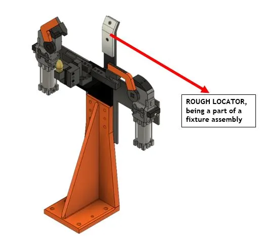
For a particular Fixture assembly, the BIW part which gets implemented on it, decides the number of rough locators required.
For example, if we want to create a BIW fixture for the Wings of an AIRCRAFT, then we require two separate BIW fixture assembly for the AIRCRAFT WINGS. One fixture for the Left-hand wing and another for the Right-hand wing.
The Rough locators are placed differently in both the fixture assembly, to differentiate the Right-hand wing and Left-hand wing.
The placement of rough locators in different orientation in both the fixture assemblies, avoids the confusion of placement of the wrong wing in the wrong fixture.
Hence, Rough locators play an important role in guiding the BIW part on the fixture assembly in right manner.
Not every time rough locators are required. The complexity of the BIW part decides the need of rough locators in the fixture assembly.
4. POINTS NEED TO BE CONSIDERED FOR DESIGNING ROUGH LOCATORS
The below following are the points that need to be considered while designing ROUGH LOCATORS: -
1.) The height of the rough locators should not be more than the permissible ergo height of the fixture.
2.) The entry point or the top point of the rough locator must be 10 – 15 MM above the panel surface.
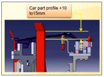
3.) Rough locators should have adjusting arrangement in the direction of the guiding plane.
4.) Rough locators can be ROD TYPE / FLAT TYPE, depending upon the standards and other conditions.
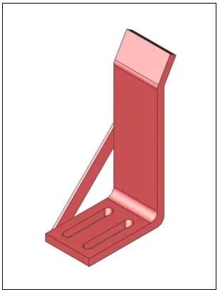
5.) There should be 2 mm gap to be maintained between the rough locator and panel at the time of design and adjusting arrangement of 5 to 10 mm in the positive or negative direction of the guide panel can be provided.
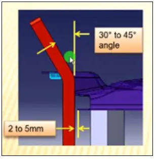
6.) The entry angle of the ROUGH LOCATOR should be between 30 to 45 degree for a certain length of the ROUGH LOCATOR, as shown in the above diagram, for guiding the BIW part in the FIXTURE ASSEMBLY.
5. GUN STUDY PROCESS
Automobile BIW is currently constructed of steel and an aluminum alloy. The BIW component is joined using a variety of metal joining techniques, such as MIG welding, to create a welded metal shell known as Body in White.
Car Body-In-White (BIW) is a complex steel structure comprising 300–500 sheets of steel with intricate shapes that are assembled using welding in rapid succession at 55-75 robotic workstations.1 A robotic welding station typically consists of the following components: a robot with a welding gun; a control system for the robot; welding equipment, if necessary, auxiliary devices.
The following points are very important for welding gun study: -
1.) We have to take the inputs from the customer about what type of welding has to be performed on the BIW parts. Whether manual welding or robotic welding based on the complexity of the BIW part.
2.) We have to know sequence of panel / BIW part loading, for which welding operation has to be performed.
3.) 2D guideline for design gun study: - This is an important study in fixture design. This gives the details of where the weld gun is located, what kind of weld gun (resistance spot welding, seam welding) is Used. The entire fixture design depends on it.
Ø Types of weld & Gun used In BIW Fixture
A.) Spot welding
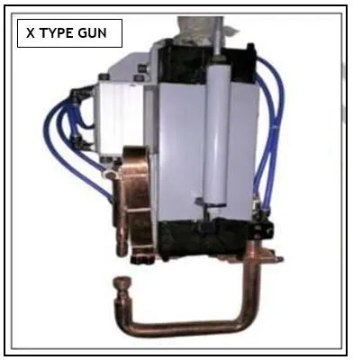
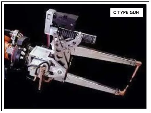
Many basic types of guns are available, the two most commonly used for Spot welding, being the direct-acting type, generally known as a “C”-Type gun, where the operating cylinder is connected directly to the moving electrode, the “X” Type (also known as “Scissors” or “Pinch”) where the operating cylinder is remote from the moving electrode, the force being applied to it by means of a lever arm. C guns are generally the cheapest and the most commonly used. There are many variations available in each basic type with regard to the shape and style of the frame and arms, also the duty for which the gun is designed with reference to welding pressure and current.
B.) Mig Welding
MIG welders use a tool called a spool gun, which feeds a spooled wire electrode at a selected speed. The gun also emits a shielding gas as it lays the weld. This gas protects the weld area from atmospheric gases such as nitrogen and oxygen, which can cause problems if they come in contact with the electrode, the arc, or the welding metal.
According to given welding data we require to add gun in 3d model which x type gun & C type gun and some arc welding also. Gun access should be important for welding after this we can build units to clear gun.
Following Gun given By Customer: -
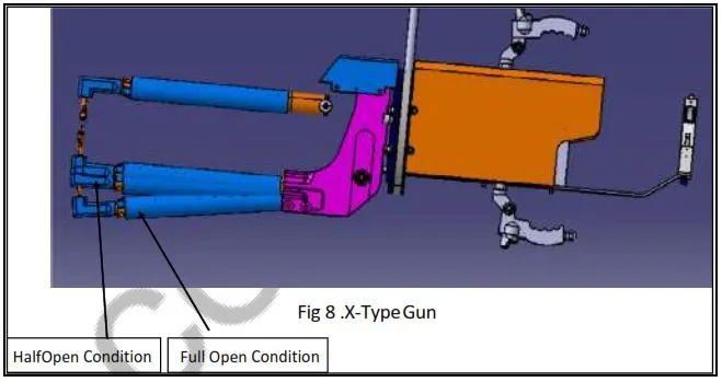
The above 3d model which is actual gun, used when welding. The gun has this actual dimension with position of gun arm while welding and open with full and half condition. This is mandatory gun data require about gun so easy to build a unit to clear gun.
6. POINTS NEED TO BE CONSIDERED DURING THE GUN STUDY
The below points are needed to be considered for the GUN STUDY: -
1.) The weld spots which are to be made on the BIW part, should be located and we have to see that, whether the weld gun can make the welding on the same spots, without hampering the BIW part.
2.) The Weld gun should have minimum motion and large access to the major portion of the BIW part, to perform the welding operation in precise manner.
3.) The Weld gun’s point of welding, should be normal to the BIW part, to have a effective welding spot.
4.) The welding time of a particular BIW part, depends on the number of weld spots that has to be made, to fulfill its requirement. The welding cycle time has to be calculated, which helps in knowing the welding time of a particular BIW part. The welding time data collected for a particular period of time, can help in improvising the welding speed of the weld gun.
5.) The WELD GUN, while preforming the welding action, should also see that the motion of the clamps should not be obstructed, during clamping and de-clamping action of BIW sequenced parts, which are the part of the welding process.
6.) The WELD GUN STUDY can be simulated with simulation software, by selecting the BIW part, which has to be welded. The weld spots are marked on the BIW part, with the help of coding and the weld gun is made to perform the welding process in the simulation software.
By the help of simulation software, we can identify where the WELD GUN can face obstruction / hinderance in performing the welding operation. The welding cycle time can also be arrived in the same software.
7. PNEUMATIC ROUTING
The below following important steps are need to be followed for ‘PNEUMATIC ROUTING’: -
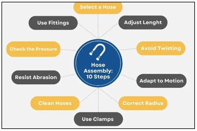
1. Select the Right Pneumatic hose
Selecting the right pneumatic hose is a critical aspect of proper pneumatic hose installation, particularly when dealing with pneumatic cylinders. It's essential to consider factors like pressure rating, temperature range, compatibility with inlet air to the cylinder, and the specific requirements of the pneumatic cylinder. Equally important is proper pneumatic hose routing to prevent kinks, abrasion, or other damage
2. Choose Proper Hose Length
It's essential to ensure that the hose's overall length provides enough flexibility and slack for the pneumatic system to operate smoothly without placing undue stress on the hose. Having adequate length allows for natural movements and adjustments within the system. However, it's equally critical not to have too long of a hose, as this can lead to tangling, increased cost, and potential safety hazards.
3. Use the Proper Bend Radius
To ensure the proper functioning and longevity of Pneumatic hoses, adhering to guidelines for the correct bend radius is essential. Each specific hose type has a designated minimum bend radius, which should not be exceeded during installation. Going beyond this limit can lead to hose failure due to kinking or internal damage. It's crucial to consult the manufacturer's specifications to determine the appropriate bend radius for the particular hose you are using.
4. Use of Clamps to Secure the Hose
We have to make sure to carefully plan and secure the hose routes, avoiding sharp bends, kinks, or contact with abrasive surfaces. Adequate clamping with appropriate supports helps maintain hose integrity and prevents vibration-induced damage. By using clamps when installing pneumatic hoses, you can enhance the overall reliability and safety of your pneumatic equipment, minimizing the risk of hose failure and system downtime.
5. Use of Elbow Fittings
Use elbow fittings or adapters, when necessary, especially when connecting hoses to pneumatic cylinders or other components. This practice is vital for a smoother hose assembly, reducing the risk of kinking or excessive bending. Properly aligned tube fittings and adapters not only improve the performance of the pneumatic system but also extend the hose's life by minimizing stress and wear.
8. SOLENOID VALVE
A solenoid valve is one which uses an electromagnetic actuator to move a hydraulic control element such as a poppet or spool.
An electromagnetic actuator takes electricity and converts it into magnetic force. Magnetic force is used to move the armature which in turn controls the spool or poppet and direction of flow.
Solenoid is a nickname given to a set of valves which use an electromagnetic actuator to shift the hydraulic control element.
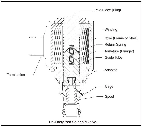
Types of Solenoid valve:-
1.) Direct Acting Solenoid Valve
Direct acting is a term generally associated with diaphragm solenoid valves or solenoid poppet valves. It means that by energising the solenoid coil, there is a direct influence on the position of the solenoid valve. For instance, if the valve is closed in its resting position (see ‘Normally Closed’ below), then energising the solenoid coil in a direct acting solenoid valve will move the diaphragm in to its open position.
It is important to note that this doesn’t necessarily mean that there is a connection between the core tube of the valve and the diaphragm, but there is a direct control as a result of the electrical state. One of the main functions of a direct acting solenoid is that they can operate fully with no pressure differential. This means that the valve can be fully operational without the need for any pressure in the line.
2.) Indirect Acting (pilot operated) Solenoid Valve
Indirect Acting Solenoid Valves, also known as ‘pilot operated solenoid valves,’ are generally always of the diaphragm style solenoid valve type. The ‘pilot operated’ term refers to the media acting as a pilot to assist with the operation of the valve. Normally, there is a small orifice in the inlet port of the solenoid valve that allows some of the media to enter into a cavity on top of the diaphragm.
In a normally closed valve, the media then applies pressure to the top of the diaphragm, holding it in the closed position. When the solenoid coil is energised, the diaphragm opens and the media is forced out of the top cavity and back into the main pressure line. The main benefit of using an indirect acting solenoid valve is the reduction in energy required compared with that of a direct acting valve. As a result, indirect acting solenoid valves are often more cost-effective.
3.) Normally Closed or Normally Open
These terms refer to the resting state of the valve, with no power applied. Although they are fairly self-explanatory, they can also be referred to using different terms. A normally closed solenoid valve can be described as ‘energise to open,’ and a normally open solenoid valve can be described as ‘energise to close.’ Normally closed or normally open most commonly refer to diaphragm or poppet type solenoid valves that employ a spring to return the valve to its resting state once the power has been removed from the coil.
4.) 2/2-Way (On-Off)
2/2-Way Solenoid Valves are generally diaphragm or poppet type valves, and can only be used for On/Off duty as there is no exhaust port. They are very versatile and can be deployed in a wide variety of applications in many different industries to simply switch flow on and off. In some instances, it is possible to have a 2/2-Way Proportional Solenoid Valve which is used to regulate flow.
5.) 3/2-Way (Sol/Spring)
The term 3/2-Way is most commonly associated with a spool type solenoid valve, although it is possible have a poppet type valve in this configuration. The term 3/2 can be extruded to mean ‘3 port, 2 position.’ This same formula can be applied to other valve types with a similar abbreviation. In their resting state, the most basic of 3/2-Way valves uses port 1 as the valve inlet, port 2 as the outlet and port 3 is the exhaust, but is blocked in its resting state. When power is applied via the solenoid, the spool position changes and port 1 becomes blocked, with port 2 flowing to port 3 and therefore exhausting the system. When power is removed, the spool springs back to its resting position and normal valve function is restored. This is why the operation of this type of 3/2-Way Spool Valve is also known as ‘Sol/Spring.’ 3/2-Way Spool Valves are most commonly used as a pilot to a Single Acting Pneumatic Actuator or Pneumatic Cylinder.
6.) 5/2-Way (Sol/Spring or Sol/Sol)
A 5/2-Way valve is also most commonly supplied as a spool type of solenoid valve. They operate in much the same way as a 3/2-Way Valve, but there are two extra ports which can be used to pilot double acting pneumatic actuators or pneumatic cylinders. They can be supplied with a single coil allowing spring return (known as Sol/Spring), or with a double solenoid coil (known as Sol/Sol).
9. VALVE BANK
Original solenoids were individual devices, requiring air tubing connections and wiring. One helpful development was consolidating many solenoids into a compact valve bank.
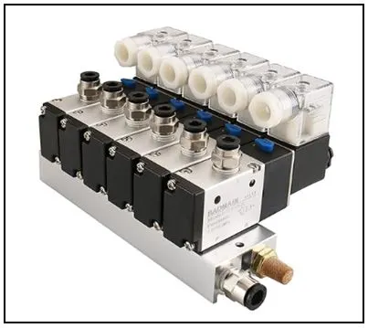
Modularity of a set of solenoid valves to form a solenoid bank was important, because there are many variations of solenoids, and each remote ‘drop’ might need just a few or perhaps a great number of solenoids. The flexible answer was a modular pneumatic system, which can include various I/O modules, network communications, and IP65 surface-mount capability.
Distributing multiple valve manifolds around a machine can also simplify tubing runs and shorten airlines to cylinders and actuators, resulting in simpler integration and faster actuator response. Some manifolds are available with environmental rating options so they can be installed away from electrical panel hazards and right on machines, even in washdown environments.
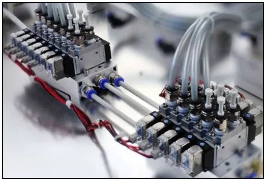
Many applications, whether they are machines with a high field device count or a conveyor line extending over long distances with a low I/O density, can benefit from smart solenoid manifolds. Modular and intelligent electro-pneumatic installations provide many options for OEMs and system designers to distribute pneumatics and I/O devices in an organized and efficient way throughout an automated machine or system.
These manifolds save space, reduce the need for control enclosures, and minimize the required effort and cost of wiring and plumbing. Users can standardize their designs on vendors, protocols, and products to meet their needs and simplify their efforts.
10. SENSOR
Sensors play a crucial role in enabling intelligent production and automated processes. They allow industrial manufacturers to measure, monitor, analyze, and process changes on machines that range from security, location, and motion to temperature and pressure.
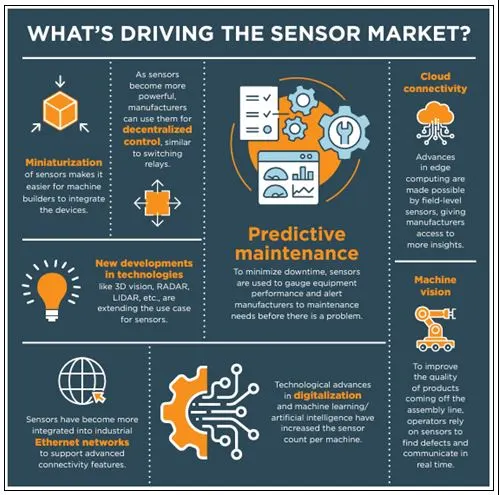
Automation of industrial and factory operations and production cannot be complete without the various applications of sensing sub-systems and sensors. Some of these applications of sensing sub-systems in industrial automations are discussed in the sections below.
Ø Industrial Applications of sensors in automation
In automation and robotics, the use of sensors or sensing sub-systems for feedback control are essential. Sensors have found typical applications in industrial automation in various ways such as:
a.) Sensing & Detection Applications
The sensors in this application include:
· Sensor AFE (Integrated Analog Front End) for many types of sensor
· Pressure/Load/Force Sensing Applications
· System Health Monitoring & Temperature Sensing
· Optical Sensing
· pH and chemical sensing
· Vibration/Motion/Humidity/other sensing
b.) Motor Control
The sensors in this application area include:
· AC Motor sensor
· Servo Motor Control
· Low-Side Motor Control
· Multiple Motor Control/Synchronization
c.) Factory Automation
These types of sensors are used to automate factory operations and processes.
They include:
· Automation and Control Networks. An example of this is Precision Ethernet PHY with IEEE 1588 PTP
d.) Test and Measurements
These types of sensors are used for automating testing and measurements in the industry. They include:
· Spectrum Analyzer
· Oscilloscope/Digitizer
e.) Imaging/Machine Vision & Display
These types of sensors are used in the industry to capture, store and display images. Robots use this type of sensors to provide what is known as robot vision. Examples of these types of sensors include:
· Security/Machine vision
· Multifunction Printer/Copier
f.) Data Acquisition Circuits for Industrial Applications
These types of sensors are highly deployed in the industrial for data acquisition processes; environmental analog data are captured by these sensors from the physical environments and converted to digital data by Analog to Digital Converters (ADC) and then feed into computer control program. These sensors are highly used where monitoring of environmental properties are required.
Examples of these types of sensors include:
· Data Acquisition System ( Up to 1 MSPS)
· Data Acquisition System ( GigaSample/sec)
· I/O Sensor Module
· LIDAR System
g.) System Health Monitoring
These types of sensors are heavily deployed in the monitoring of system health industry. They are used to sense and detect different system’s health parameters. They include:
· Integrated System health monitors ICs
· Voltage monitoring using ADCs
· Analog temperature sensing
· Temperature switches
· Remote diode temperature
· Thermocouple solutions
· Resistance Temperature Detectors (RTDs)
h.) Other Application areas for industrial sensors
Apart from the application areas mentioned earlier where industrial sensors can
de deployed, these sensors are equally used in these application areas:
· Automatic lens grinder depth indicator
· Electronic assembly
· Endurance Testing
· Hydraulic Presses
· Instrument Testing (Torque)
· Material Testing
· Multiple set point smart switch for machine control
· Nut runner, Torque control
· Operation control
· Overload Protected Tactile Sensor
· Position control smart switch
· Propulsion systems
11. TYPES OF SENSORS
The portfolio of sensors is as varied as the industrial applications they serve. From the detection of physical quantities like temperature and pressure to scrutinizing the molecular composition of substances, sensors have become incredibly specialized tools.
The types of sensors widely used in the industrial automation is shown below: -
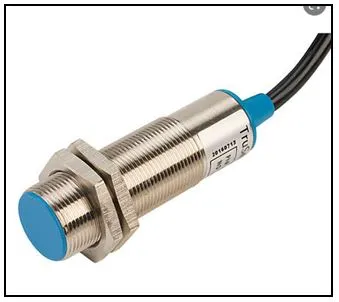
a.) Proximity Sensors
In scenarios where detecting the presence of an object without physical contact is essential, proximity sensors are the go-to solution. These sensors commonly use electromagnetic fields and can differentiate between various materials, making them invaluable in material handling, bottling lines, and safety gates.
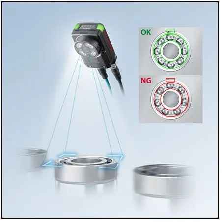
b.) Vision Sensors
Vision sensors, equipped with cameras and image processing systems, can perceive and inspect objects, verify positions, and identify parts. In automated assembly lines, they ensure the correctness of each step, playing a crucial quality control role.
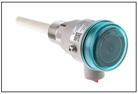
c.) Level Sensors
Maintaining the right levels of liquids and granular materials is a critical aspect of many manufacturing processes. Level sensors come in different designs, including ultrasonic, capacitance, and float switches, providing accurate measurements and contributing to the automation of material handling systems.
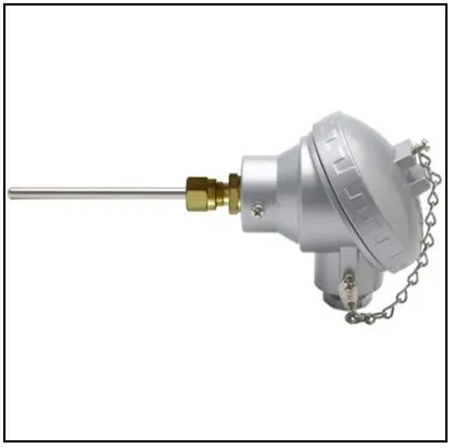
d.) Temperature Sensors
Temperature is a parameter of paramount importance across various industries, from food processing to machinery operation. Thermocouples and resistance temperature detectors (RTDs) are commonly employed to monitor and regulate temperature, ensuring processes operate within their prescribed range.
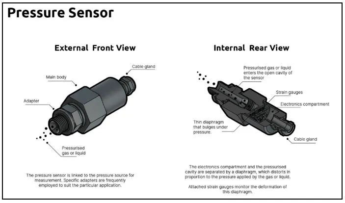
e.) Pressure Sensors
Pressure is another measurable quantity that carries important process data. Whether in pneumatic systems, hydraulic systems, or clean room environments, pressure sensors aid in maintaining optimal operating conditions and flagging off deviations.
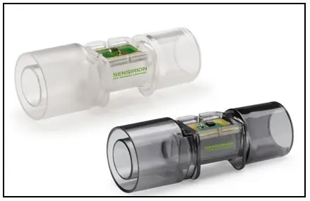
f.) Flow Sensors
In continuous production processes like those found in chemical manufacturing, the rate of flow can be critical. Flow sensors monitor and regulate the flow of gases and liquids, managing consumption, and ensuring the right volume is maintained in the right place at the right time.
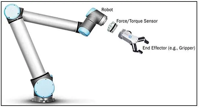
g.) Force and Torque Sensors
For applications involving material testing, robotic assembly, or machine monitoring, force and torque sensors assist in measuring mechanical loads. They are indispensable in ensuring the integrity of equipment and the quality of the products.
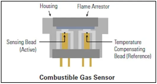
h.) Gas and Chemical Sensors
In environments where specific toxic or flammable gases need to be monitored, gas and chemical sensors provide the necessary vigilance, often integrated in safety systems that can shut down operations when necessary.
12. FUNDAMENTAL POINTS TO BE CONSIDERED FOR DESIGNING / SELECTING A SENSOR
Fundamental points to be considered while designing / selecting a sensor is shown below,
Ø Material Selection for the Sensing Element
The choice of material for the sensing element is a critical decision in sensor design, as it directly affects the sensor's performance and suitability for its intended application. Several key considerations must be taken into account:
Type of Measurement: The nature of the physical phenomenon being measured (such as temperature, pressure, humidity, light, etc.) largely dictates the material choice. For instance, thermocouples for temperature measurement typically use different metal alloys, while piezoelectric materials are chosen for pressure sensors.
Accuracy and Precision: The selected material should enable the sensor to perform measurements with high accuracy and precision. This involves minimal deviation from the true value (accuracy) and consistent performance over repeated measurements (precision). Certain materials are inherently more stable and provide more reliable readings.
Sensitivity: Sensitivity refers to the degree of responsiveness of the sensor to changes in the measured parameter. The material should exhibit a significant and measurable change in its properties (electrical, optical, mechanical, etc.) even with slight variations in the stimulus.
Range and Operating Conditions: The material must withstand the full range of expected operating conditions without degradation. This includes considerations of temperature range, humidity levels, exposure to chemicals or radiation, and mechanical stress, ensuring the material's stability and longevity under these conditions.
Response Time: The time a sensor takes to react to a change in the measured parameter is crucial, especially in applications requiring real-time monitoring or control. Materials with faster response times are preferred in dynamic environments to ensure timely data collection and processing.
Ø Power Considerations
In the design of sensors, power considerations hold paramount importance as they substantially influence the sensor's efficiency, longevity, and practicality. Proper attention to energy consumption and power sources is vital, especially for portable and remote applications where energy resources are limited or inaccessible.
Energy Harvesting
Energy harvesting is an innovative technique to garner energy from the surrounding environment, converting available ambient energy forms, such as light, heat, or motion, into electrical energy to power the sensor. This strategy can significantly extend the operational life of the sensor, reduce dependency on external power sources, and facilitate the deployment of sensors in isolated or harsh environments.
For instance, photovoltaic cells can harvest energy from sunlight, thermoelectric generators can exploit temperature gradients, and piezoelectric materials can convert mechanical stress or vibrations into electrical energy. The choice of energy harvesting method should align with the environmental conditions and energy availability at the deployment location to ensure consistent and sufficient power supply.
Low-Power Design
Implementing low-power design principles is crucial to optimize energy consumption and prolong battery life. Techniques such as duty cycling, where the sensor periodically enters a low-power sleep mode, can significantly reduce power consumption. The integration of low-power components, efficient signal processing algorithms, and power management systems are essential to maintaining high performance while minimizing energy usage.
Adaptive sampling rates and dynamic power scaling can further optimize power consumption based on the current operational demands and environmental conditions. Ensuring the sensor operates only when necessary and at the lowest sufficient power level contributes to energy conservation and extended operational life.
Battery Selection
Choosing the appropriate battery is another critical aspect of power considerations, entailing the evaluation of capacity, weight, lifespan, and environmental conditions. The battery should provide sufficient energy to sustain the sensor's operation between charges or replacements, considering the energy demands of sensing, processing, and communication activities.
The weight and form factor of the battery should align with the design constraints of the sensor, especially in wearables and airborne applications where weight and space are at a premium. Assessing the operating temperature range, rechargeability, and environmental impact of the battery is also crucial to ensure reliable operation and compliance with environmental standards.
Integration and Optimization
Seamlessly integrating energy harvesting technologies, low-power design principles, and appropriate batteries requires meticulous design and optimization. Balancing energy supply and demand, while accommodating the practical constraints and operational requirements of the sensor, is essential to realize efficient, sustainable, and reliable sensing solutions.
Power considerations are integral to the successful design and deployment of sensors. Energy harvesting, low-power design, and thoughtful battery selection are pivotal strategies to address the energy constraints and enhance the sustainability and reliability of sensors. Optimizing these elements according to the application's needs and environmental conditions is imperative to advance sensor technology and expand its applications in various domains.
Ø Design for Specific Applications: Wearables, Industrial, Airborne
Wearables: For wearable applications, the sensor's form factor must prioritize user comfort, aesthetics, and ergonomic integration. The designs are typically compact, lightweight, and flexible, allowing seamless integration into clothing, accessories, or directly onto the skin. Bio-compatibility and skin-friendly materials are crucial to avoid irritation or adverse reactions. Packaging for wearables should also consider protection against environmental factors like moisture and dust, and enable unobtrusive and continuous monitoring of physiological parameters or environmental conditions.
Industrial Applications: In contrast, industrial applications often necessitate robust and durable form factors capable of withstanding harsh environments, such as extreme temperatures, corrosive substances, or high pressures. The packaging needs to be resilient, protecting the sensor elements from physical damage, contaminants, and electromagnetic interference. Integration with industrial equipment might require customization to align with existing systems and workflows, ensuring accurate and reliable sensing without disrupting normal operations.
Airborne Devices: Airborne sensor applications, such as those in drones or satellites, demand form factors that optimize aerodynamics, weight, and space utilization. The materials and packaging must endure high-altitude conditions, extreme temperature fluctuations, and mechanical stresses encountered during flight. Secure mounting, minimal drag, and efficient heat dissipation are essential design considerations to prevent malfunctions and ensure sustained performance in airborne conditions.
Adaptation to Specific Applications: Regardless of the application domain, the form factor and packaging should be tailored to the specific requirements and constraints of the intended use. This may involve innovative design approaches to accommodate unique shapes, sizes, mounting options, and protection levels. Modularity and scalability in design can offer versatility, allowing adaptation to various applications without significant modifications.
User Interface and Accessibility: The design should also consider user interactions, including display readability, button accessibility, and connectivity options, ensuring user-friendly operation and data access. For applications requiring user input or feedback, intuitive interfaces and clear indication of sensor status are vital to facilitate user engagement and accurate data interpretation.
Form factor and packaging are integral components of sensor design, significantly impacting the sensor's functionality, integration, and user acceptance in diverse applications. Thoughtful consideration of design elements, tailored to the specific needs and constraints of wearables, industrial settings, and airborne devices, is crucial to developing effective and reliable sensors. Balancing practicality, innovation, and user-centric design is key to advancing sensor technologies and broadening their applicability across various domains.