Week 8:- 3D Finishing Challenge 2
AIM
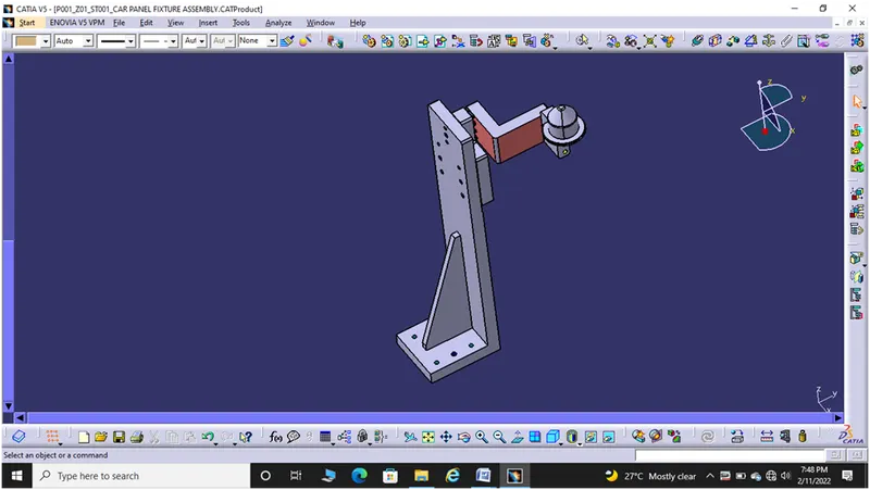
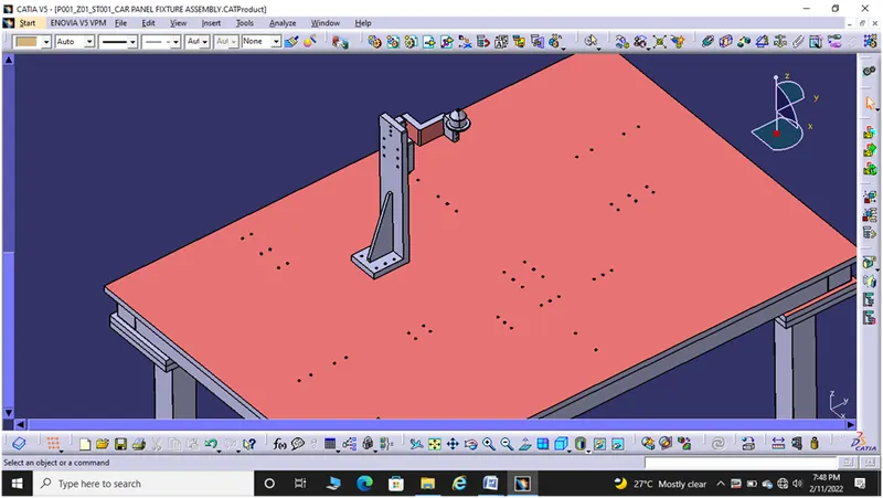
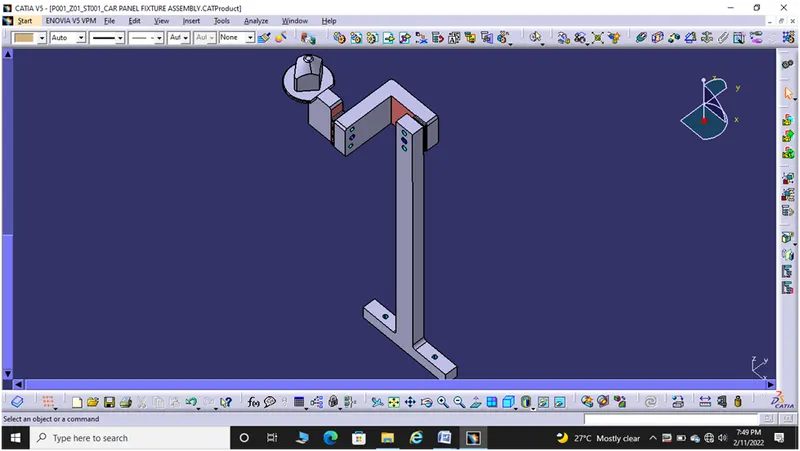
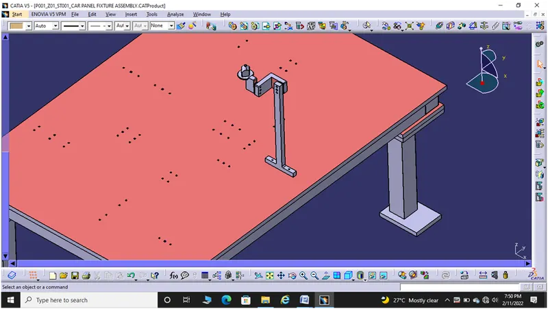
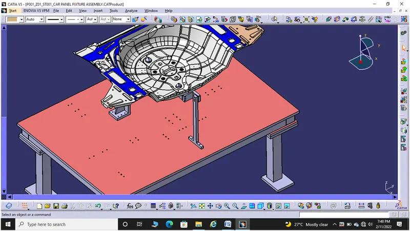
To Perform 3D finish and create rough locators for the assembly design created for the given car panel.
3D FINISHING
- 3D finish is the process where design is being completely finish & to be ready for final simulation & 2D detailing.
- While finishing the design the nominality of holes is checked which ensures the easy assemble of all the units.
- The hole concentricity & holes size are checked which ensures the easy assembly of different parts.
- The gaps between the different units are used to ensure the easy assembly of all units.
- Fasteners are implemented as per the hole size & the standard color codes as per the customer requirements are applied to differentiate the type of hole whether it’s a simple hole, threaded hole or counter bore hole.
- Renaming the assembly & the part is done to give every part a different identity. So everyone can identify in which assembly the particular part is going to be fit.
- After doing all these things the model is sent for to simulation department to simulate the design with robots whether the gun is clashing or not & 2D detailing.
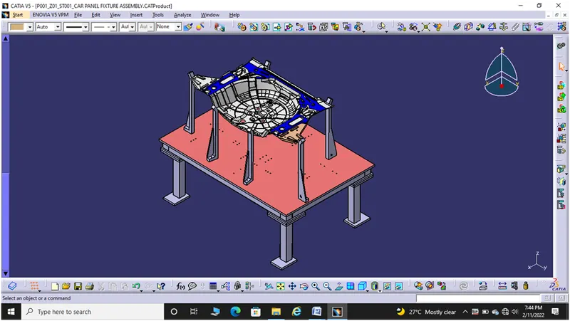
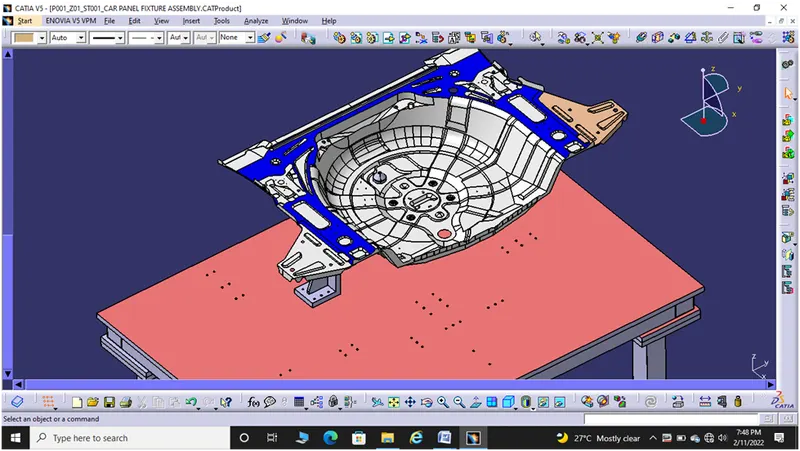
CAR PANEL
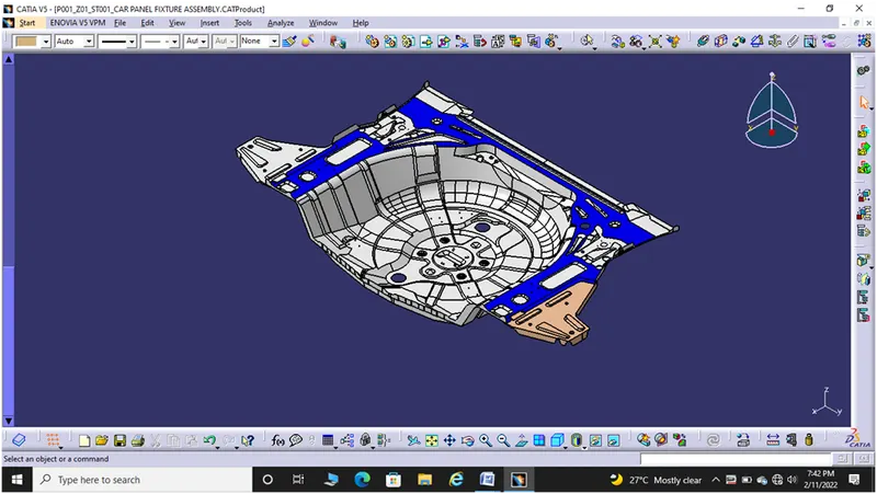
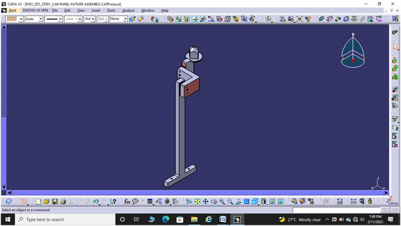
ROUGH LOCATORS
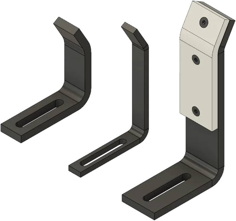
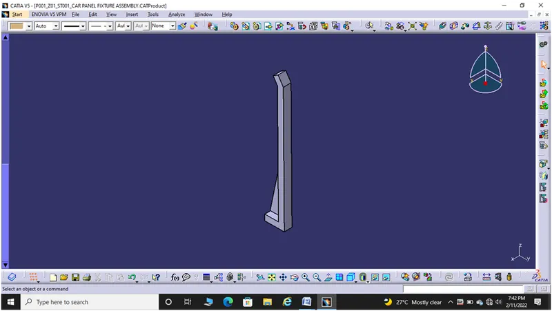
- Rough locators are basically used where manual loading of panel is implemented on the fixture.
- These are used to guide the panels to correct positions and orientation,
- These also helps for proper POKA-YOKE
- POKA-YOKE is a Japanese term that means ‘mistake proofing’ or ‘Error proofing’).
- It is any mechanism in any process that helps an equipment operator avoid (yoke) mistake (poka).
- Materials used for rough locators are Mild steel (MS) or other similar materials.
POINTS TO BE CONSIDERED WHILE DESIGNING ROUGH LOCATORS
- Height of the rough locators should not be the ergo data of the fixture.
- The entry point or top point of the rough locator must be 10-15mm above the panel surface.
- Rough locators should have the adjustment in the direction of guiding plane.
- 2mm gap to be maintained between rough locator and the panel at the time of design and we can provide 5-10mm in the positive or negative direction of guiding plane.
- Rough locators can be rod or flat type depending upon the standards and other conditions.
GUN STUDY
- Welding is mostly used in automobile industries and their requirements for fixtures that ease the welding process is a continuous developments task in any industry.
- In weld study process, the major procedure is to insert the gun in the total assembly and place the gun on the weld spots by creating a point on the tip.
- Adjust the weld gun for not getting any clashes from the 3D concept.
- Once all the weld spots are cleared without any clashes and it will be moved on to next procedure of simulation.
- In simulation, first the reach with respect to the weld spots has to be checked. Because robots are also having some limitations if it exceeds the robot will not work proper with 100 percent.
- So First we have to move and adjust the weld gun to identify the reach and to check for any clashes and adjust it accordingly.
- Car Body in White (BIW) is a complicated steel structure including 300-400 sheets with complex shapes and assembled by means of welding in a high rhythm through 55-75 robotic work stations.
- The fore most step taken before starting the welding fixture design, we must declare weld spots location for each and every panel.
- The location and orientation of other critical units of the fixture including clamps, locators, etc. are decided based on the weld spot distribution.
- In weld study, which gun and welding process has to used for fixture is to identified and decided. Gun has two different types and they are as follows.
- C-Type gun
- X- Type gun
C- TYPE GUN
- In C- type gun, one arm side is fixed and another arm is movable in linear direction of perpendicular to other arm. (Horizontal direction with respect to other arm)
- It includes the study of the weld matrix & the weld point positions. There are two types in weld point one is Geo weld which ensures the geometry of the assembly & second is Re- Spot weld points which adds strength to the welded parts.
- The fixture is designed for the car panel to hold it on the position, so we ensures that all the weld spots and weld gun do not access or any clashes with fixture tool.
- If any clashes defined while designing fixture, then we will only have to move on to redesign the tool.
- We have no permission to change a weld spot or clamping position without considering clients.
X- TYPE GUN
- In X-type gun, one arm is fixed and another arm is movable in angle position. (It moves like an arc)
- It includes the study of the weld matrix and the weld point positions.
- There are two types in weld point one is Geo weld which ensures the geometry of the assembly & second is Re- Spot weld points which adds strength to the welded parts.
- The fixture is designed for the car panel to hold it on the position so we ensure that all the weld spots and weld gun do not access or any clashes with fixture tool.
- If any clashes defined while designing the fixture, then we will only move on to redesign the tool.
- We have no permission to change a weld spot or clamping position without considering clients.
3D FINISH
In 3D finish the following points are considered and ensured.
- Naming the parts
- Structuring of design tree
- Holes Concentricity
- Nominality
- Machining surfaces
- Mylar Splitting
- Gaps checking
- Budding of parts
- Check for any clashes and make necessary changes
- Tooling hole
- Fasteners (Bolt, Nut, Washer,etc.)
COLOUR CODES
Threaded Hole- Yellow
Clearance Hole- Cyan (Sky blue)
Dowel Hole- Blue
Machining Surface- Orange
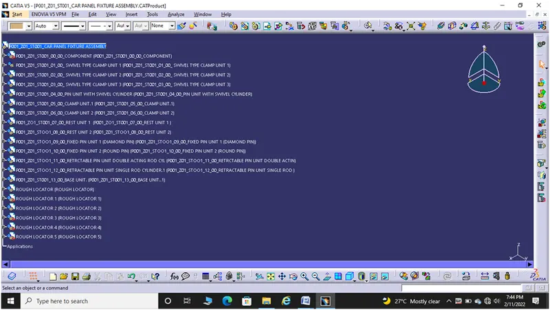
DESIGN OF TREE STRUCTURE
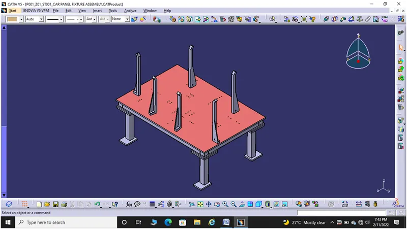
BASE UNIT
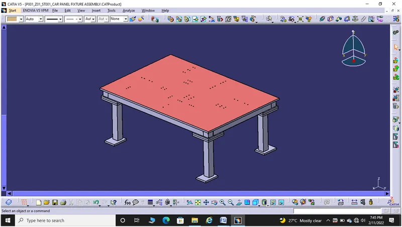
- Base unit is the unit in which all the other units are mounted on it.
- Threaded holes and dowel holes should be done at nominal positions and color must be done to distinguish the holes easily.
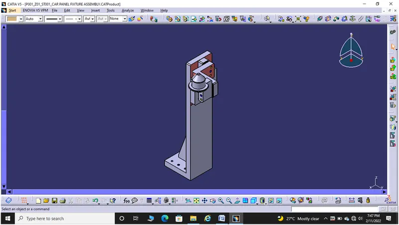
FIXED PIN UNITS
- Holes are made to the nominal and concentricity of the holes is checked.
- Proper budding of two parts is done.
- Colour codes are as per the standards.
- Structuring of design tree and renaming of parts are done.
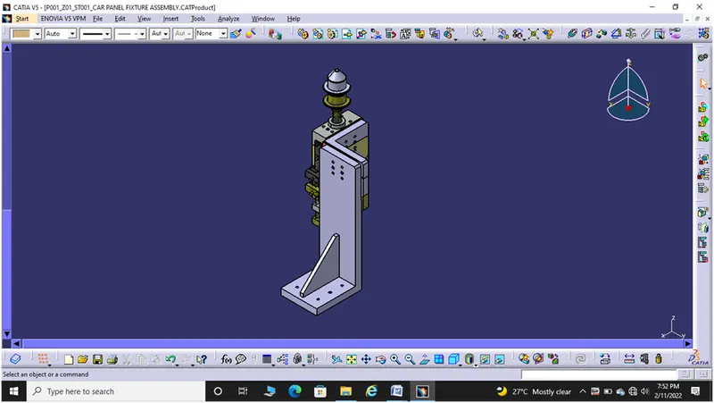
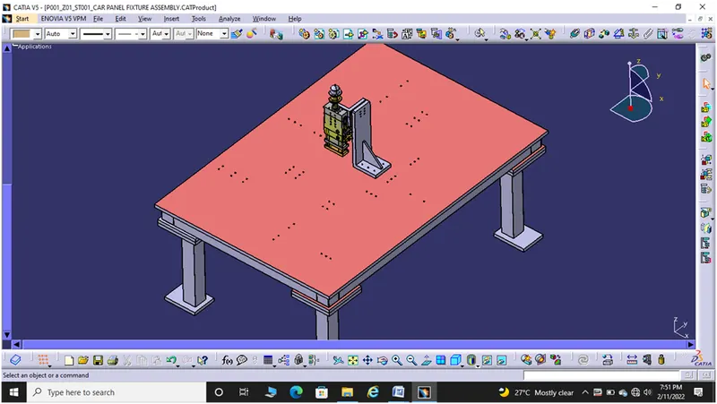
RETRACTABLE PIN UNIT
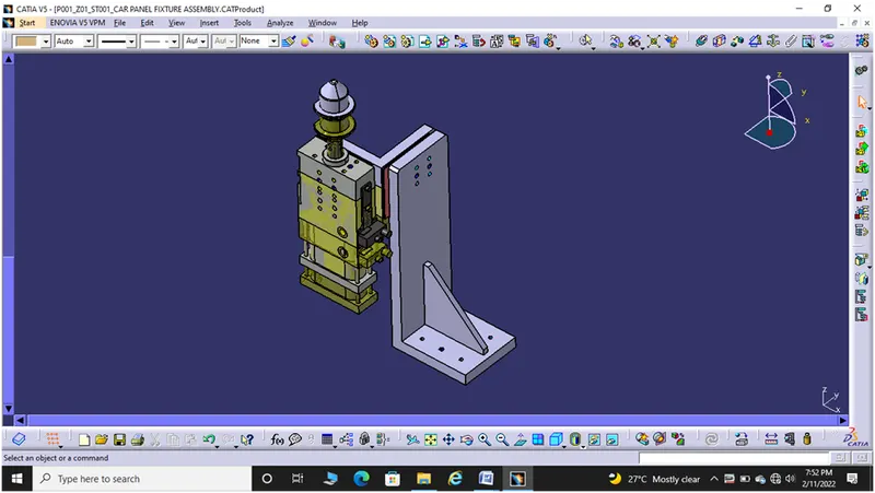
- Holes are made to the nominal and concentricity of the holes is checked.
- Open position of retractable pin unit shown in light colour of optimacity of 25 %.
- Proper budding of 2 parts is done.
- Colour codes are as per the standards.
- Structuring of design tree and renaming of parts are done.
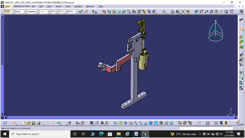
SWIVEL CLAMP UNIT
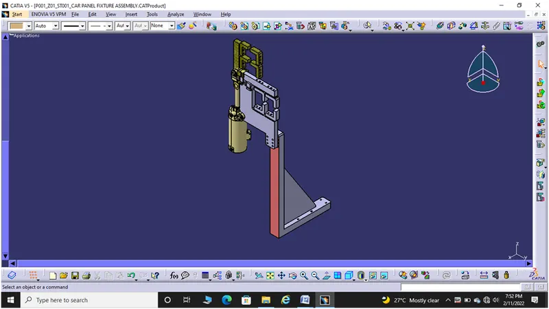
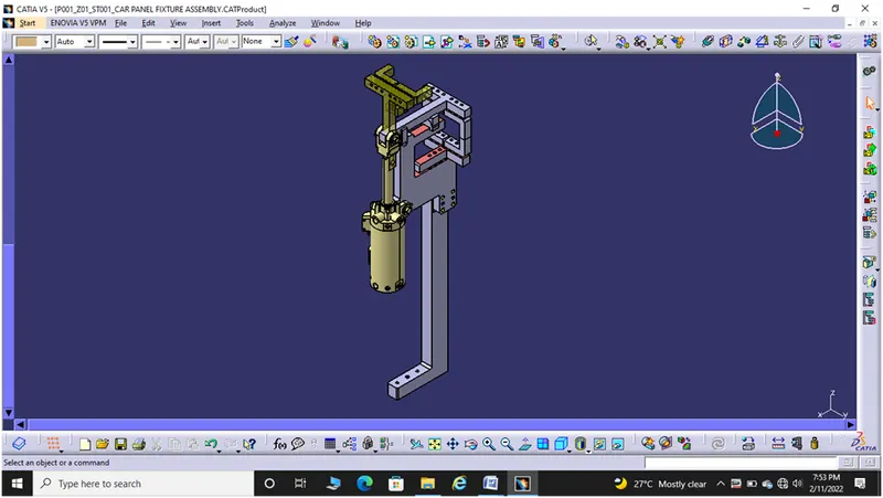
- Holes are made to the nominal and concentricity of the holes is checked.
- Proper budding of two parts is done.
- Colour codes are as per the standards.
- Structuring of design tree and renaming of parts are done.
- Mylar spitting is done.
- Consider the thickness of panel is 1mm.
- Open positions is shown in yellow color.
- Move the entire unit to nominal position with respect to base unit and put holes to the base unit.
TYPE 1
TYPE 2
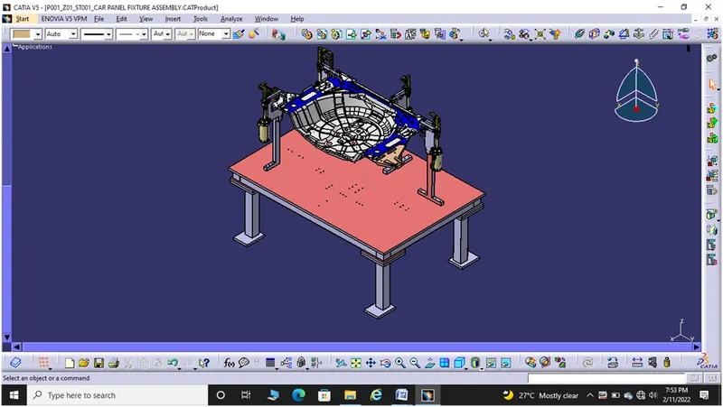
TYPE 3 (PIN UNIT AND CLAMP UNIT WITH SWIVEL CYLINDER)
POWER CLAMP UNIT
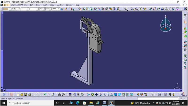
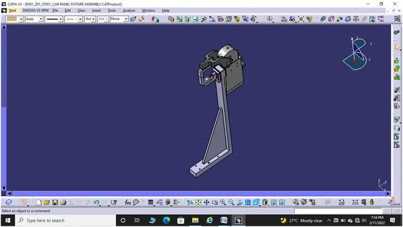
- Holes are made to the nominal and concentricity of the holes is checked.
- Proper budding of two parts is done.
- Colour codes are as per the standards.
- Structuring of design tree and renaming of parts are done.
- Mylar spitting is done.
- Consider the thickness of panel is 1mm.
- Open positions is shown in yellow color.
- Move the entire unit to nominal position with respect to base unit and put holes to the base unit.
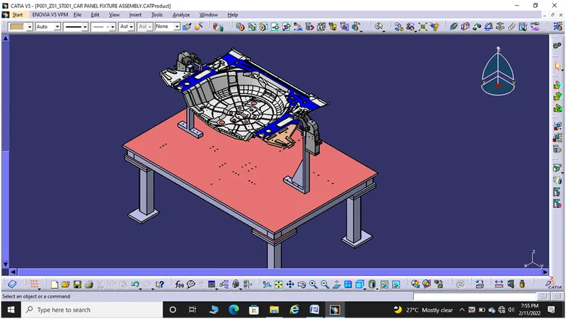
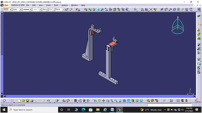
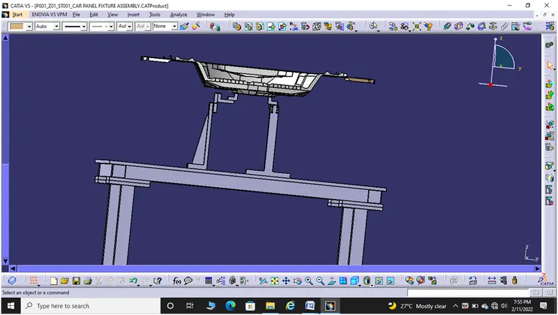
REST UNIT
- Holes are made to the nominal and concentricity of the holes is checked.
- Proper budding of two parts is done.
- Colour codes are as per the standards.
- Structuring of design tree and renaming of parts are done.
- Open positions is shown in yellow color.
- Move the entire unit to nominal position with respect to base unit and put holes to the base unit.
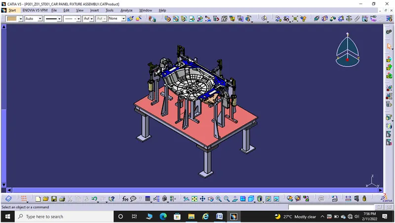
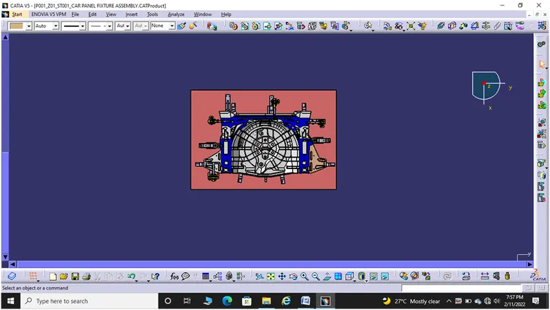
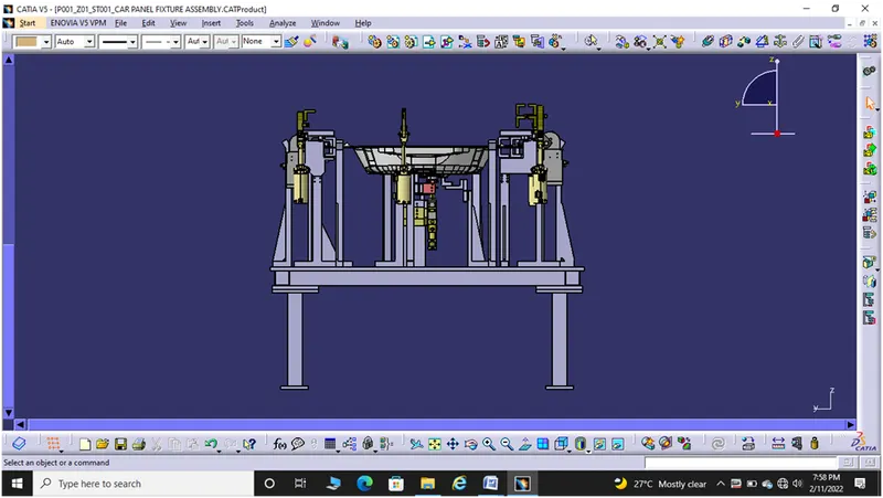
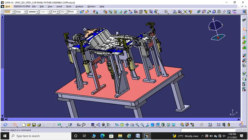
FINAL IMAGE OF FIXTURE ASSEMBLY WITH COMPONENT
CONCLUSION
Hence all the units required and the rough locators for the car panel fixture are designed as per design standards and thus 3D finish also perfomed as per given standard requirements.