Week 8
MORPHING TO THE SHEETMETAL COMPONENT
AIM:The aim of this project is to do the morphing for the sheetmetal component.
OBJECTIVE:Here we are going to do morphing for the given sheetmetal component,which changes the shape of the geometry,followed by learning the techniques in morphing tab.
METHODOLOGY:
- Import geometry.
- Topo clean up.
- Creating morphing box.
- Changing the geometry shape.
INTRODUCTION:The term MORPH means,change smoothly from one image to another by small gradual steps using computer animation techniques.In automobiles morphing is used to change the geometry shape of the component without giving the numerical inputs.It can be done in many ways.Here we are going with basic morphing called free free morphing method.In this we can just give the direction for the geometry for any design change.
PROCEDURE:
STEP 1:Import the geometry.
- After opening ANSA go to file command and open the model.
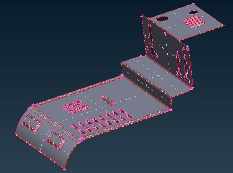
fig 1:Image showing the input model.
STEP 2:TOPOLOGICAL CLEAN UP
- After importing the model check for topological errors.
- If the errors are present then resolve it by automatic or manual method.
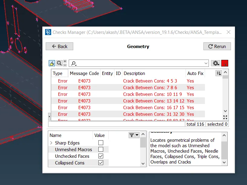
fig 2:Image showing the errors.
- Select all the errors and do fix the errors by automatically
- Some triple cons will not be solved by automatic method,then solve it manually by releasing the cons.
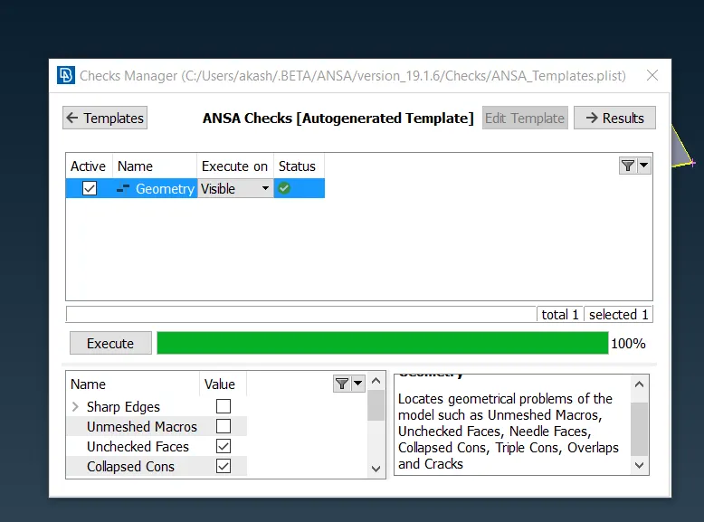
fig 4:Image showing the model without errors.
STEP 3: CREATE A MORPHING BOX
- After resolving the errors create a morphing box in morph tab.
- In morph tab go to new boxes -ortho-geometry and create a box.
- this box hepls us to move the geometry.
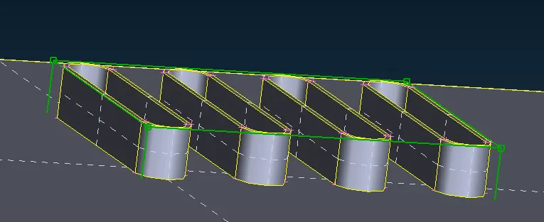
fig 5:I mage showing the morph box.
- The green colour line represents the box and the box edges at the corner.
- Now select the move option in box morphing.
- Select the nodes which are in green colour and middle click the mouse.
- Now we can move the box in any direction and angle and click enter.
- The geometry is now in a new position.
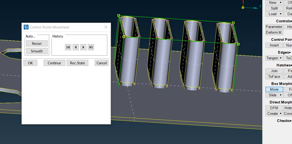
fig 6:Image shohwing the morph geometry
- Now we can observe that the geometry has increased in size.
- This is based on global coordinate.
- if we need we can right click anywhere in the box to get a local coordinate.
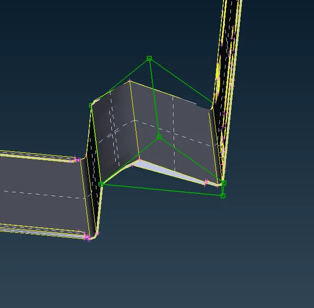
fig 7:Image showing morphing
SPLITTING MORPH BOX:
- MOrph box can be splitted by split option in morph tab.
- This allows us to change the very minute design in geometry.
- Go to split in modules.
- Select the morph box which need to be slpitted
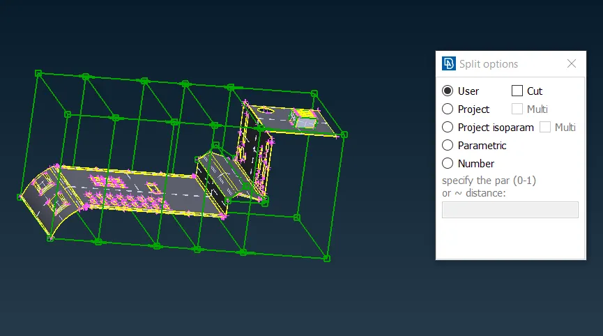
fig 8:Image showing splitting morph box.
- Select the minute part to be morph,and make the node move,so that minute part can be morphed.
- We can split each morph box either in horizontal or vertical direction.
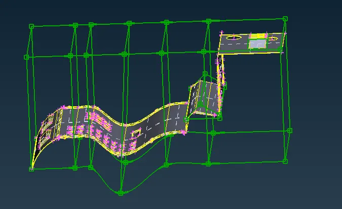
fig:Image showing split morph
BEFORE MORPHING AFTER MORPHING:
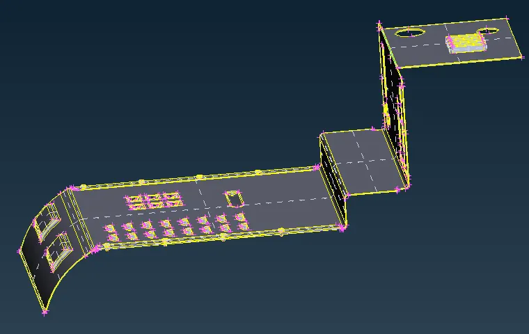
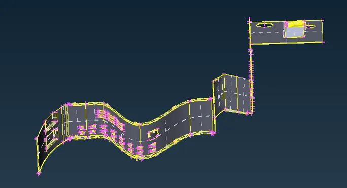
fig:images showing before and after morphing.
LEARNING OUTCOMES:
- Learnt about morphing and its uses.
- Able to do morphing for sheet metal components.
- Able to change the geometry without numerical values.
CONCLUSION:From this we got to know that the geometry can be changed without numerical values through morphing.It can be done with various methods.For every sheet metal component the above procedure is same.
LINK OF THE PROJECT: https://drive.google.com/file/d/14FesqrfG-nDusGRbiSq56GotFyRsX2z_/view?usp=sharing