Morphing the given component with various techniques using ANSA
AIM: Morphing the given component with various techniques.
KEYWORDS: Morphing, Topo, Wrap tools, etc.,
SOFTWARE: Ansa
OBJECTIVE:
( i ) For the given component check for the geometrical errors.
( ii ) After the clean up the geometry errors, morphing the component.
( iii ) Morphing the component can be done for either geometry or FE model.
INTRODUCTION:
ANSA encompasses a full-fledged Morphing menu which is completely integrated with ANSA's interface and doesn't require any additional module installations or licenses. The functions of the Morphing menu can be used to efficiently re-shape both FE and/or Geometry based models. In Morphing there are various techniques included,
Direct Morphing:
ANSA’s Direct morphing features gives the user the ability to efficiently modify a part locally without having to create Morphing boxes. This method is extremely useful in creating local modifications on single parts. Creation of depressions, surface fitting certain FE part features to new target geometry, moving selected features along the contour of a surface, and also the ability to freeze (rigid) elements during the morphing process are some of the direct morphing abilities
Parametric Morphing:
The desired morphing actions can be saved as parameters that can be accessed in batch mode. Users can enforce desired shape changes by changing the numerical input value for the appropriate parameter. This method of morphing is highly utilized for coupling the morphing operations to an external optimizer. The scripting capability can be used in conjunction with ANSA’s parametric morphing functionality to deliver faster DOE models.
Geometry Morphing:
ANSA brings to the CAE world its – of – kind’ tool for CAD geometry morphing. This pioneering concept allows the user to utilize the inventory of all the familiar FE morphing functions to perform equivalent operations in a CAD environment on geometric entities.
Domain (Box) Morphing:
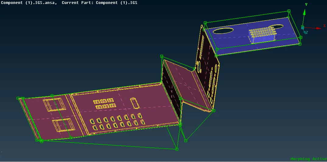
Domain or Box Morphing is performed via boxes that are created around a particular part or assembly that the user intends to morph. The movement of the Morphing boxes control points defines the morphing operations on the entities inside the Morph box. This type of Morphing can be applied to both FE and Geometry based models. The morphing has done on a certain area and shown in the below figure,
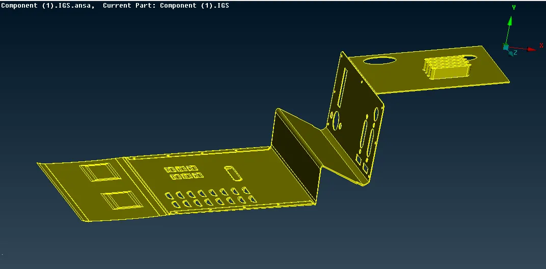
Actual Component: The component checked for geometry errors and the below figure shows the component before morphing,
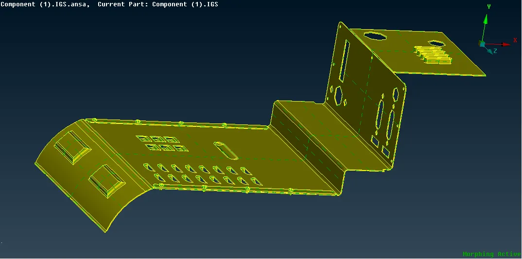
Component After Morphing: After cleaning up the geometry error started the various morphing techniques in the component. It can be identified when compared with the actual model how morphing has been done and acts a major role in the component.