Week 7 State of charge estimation
Test case 1:
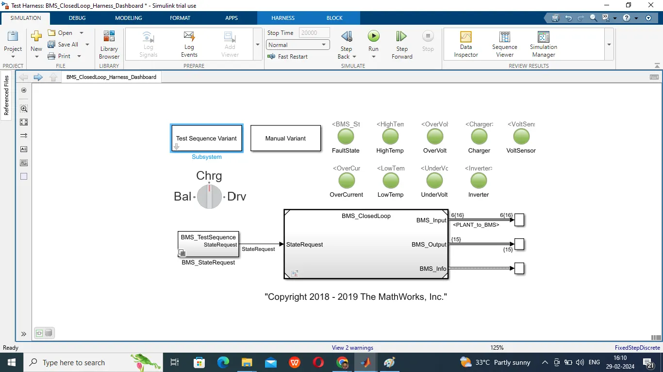
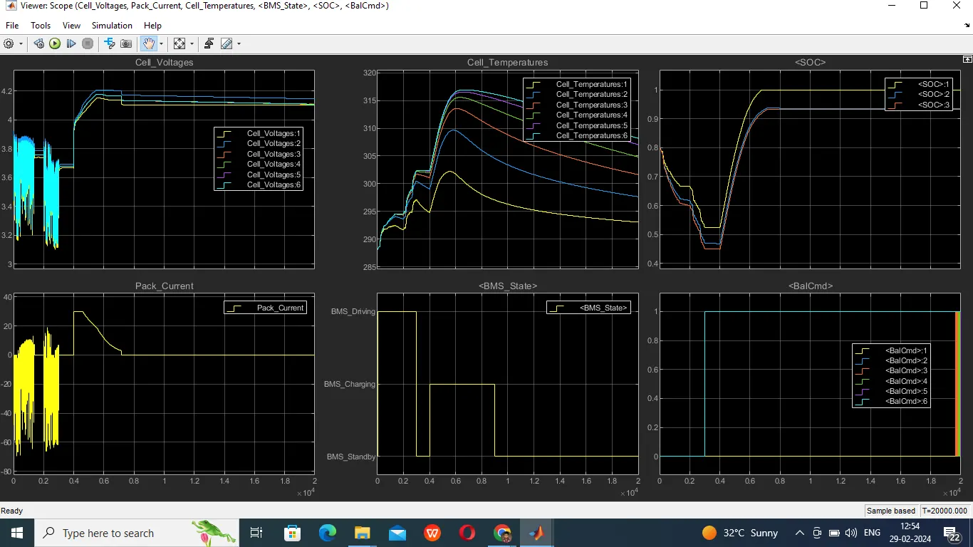
Initially the BMS is in Driving state where battery pack supplying and getting rechared from regenerative breaking. The positive Pack_Current indicates charging of cells and negative Pack_Current indicates discharging of cells. The cell 1 is having minimum voltage than the other cells so BalCmd signal is issued for remaining cells. When Pack_Current is zero the BMS is in standby state. The batterey pack is connected to charger from 4000 to 7000 seconds and BMS state changed to BMS_Charging state
where it is charged initially in constant current mode later to constant voltage mode and when Pack_Current is zero the BMS state changed to standby mode. Even at 9000th second the cells are not balanced so the BalCmd signal is still enabled for cells other than one and in between 18000 to 20000 cell3 and cell4 having similiar voltage with cell1 so BalCmd is having some oscillations. The cell SOC is calculated using Coloumb Counting Method, Unscented Kalman Filter, Extended Kalman Filter.
The Coloumb Counting is shown by SOC1 waveform. Unscented Kalman Filter and Extended Kalman Filter are shown by SOC2, SOC3 waveforms. As all parameters are with in the limits so
no fault signal is generated
Test case 2
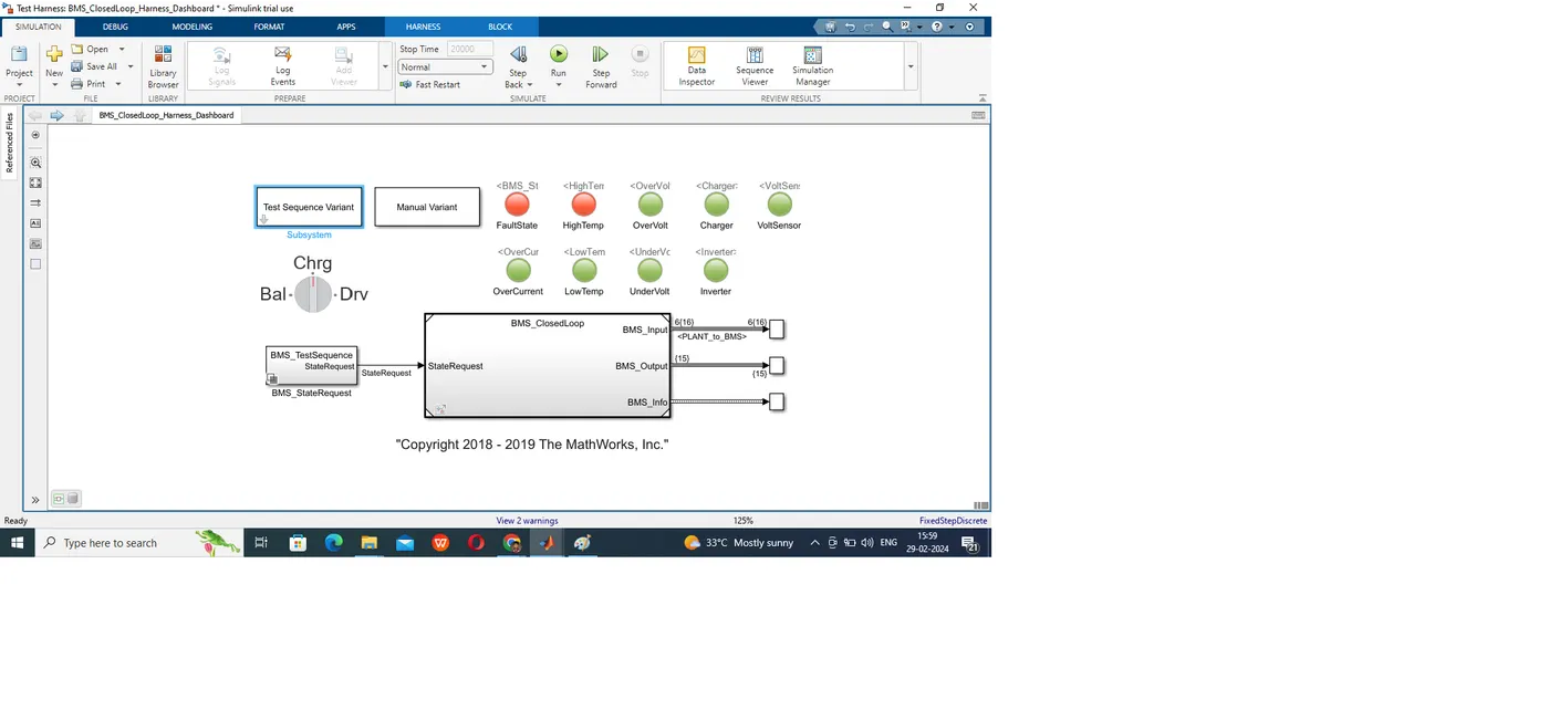
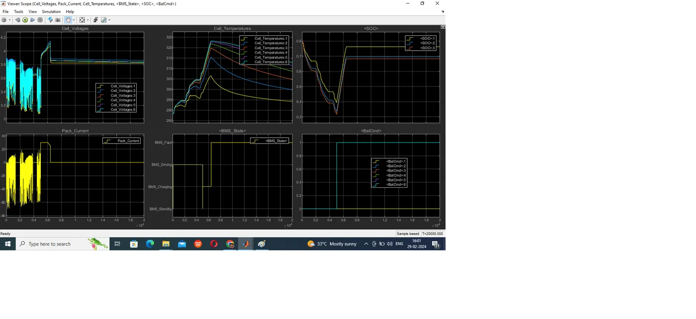
The BMS is in driving state till 5000th second where battery is discharging and getting charged from regenerative breaking and all cells are having similar voltages so no BalCmd signal is enabled. After 5000th second battery pack is getting charged in constant current mode and BMS is indicating charging mode and cell 1 having less voltage than the other so BalCmd signal got enabled for cells other than one and after constant current mode the cell 6 reached maximum temperature and a fault signal is generated under high temperature and BMS disconnected the battery pack and BMS entered fault mode but cells balancing is not stopped till end of simulation. Battery pack SOC is calculated using Coloumb Counting Method, Unscented Kalman Filter, Extended Kalman Filter and SOC1 waveform indicates Coloumb Counting method, SOC2 and SOC3 waveforms indicates Unscented Kalman filter and Extended Kalman Fiter
Test case 3
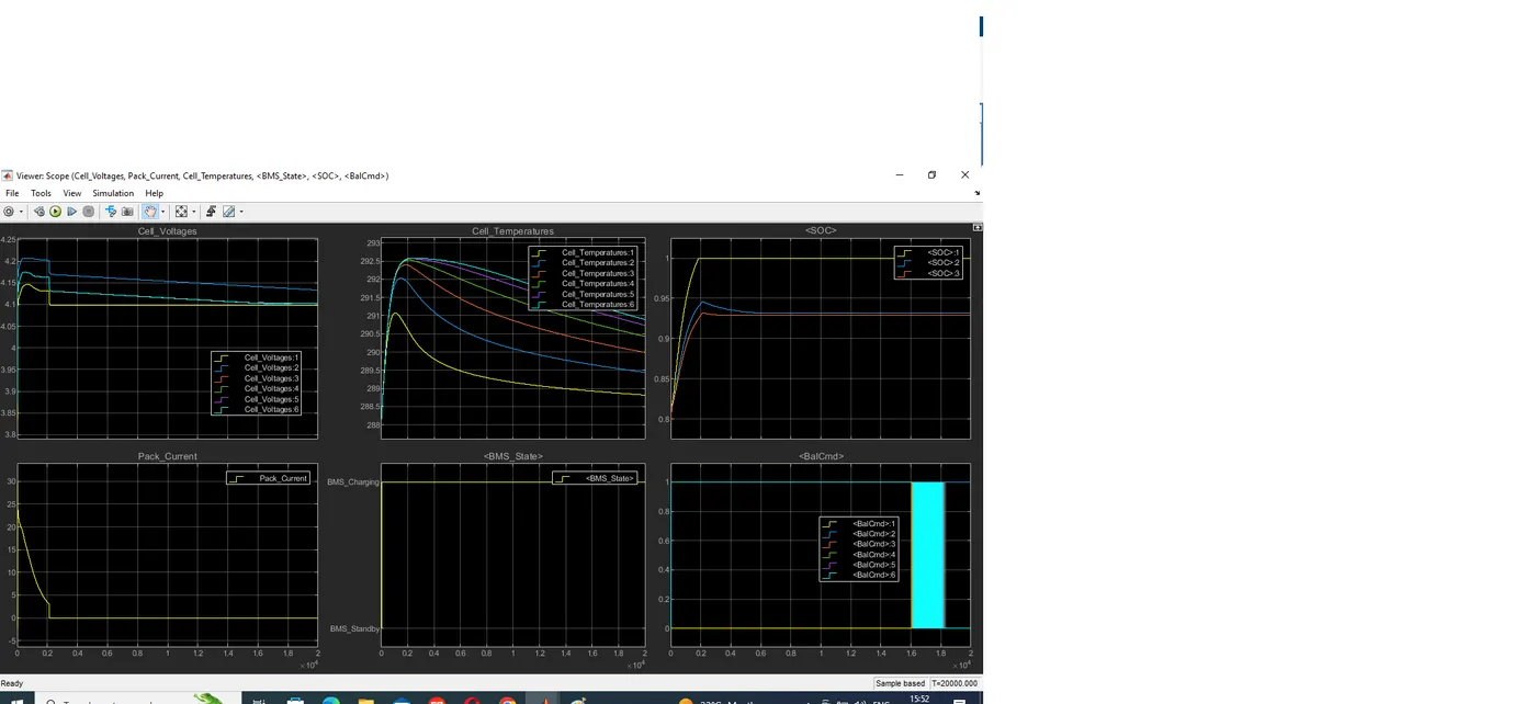
In this test BMS is in Charging state and charged in constant voltage mode. As the cells are far from balance the BalCmd signal is enabled from beginning for cells except cell one. After 2000th second the pack curretn became zero and as charging is completed but cells are not balanced so BalCmd signal is still in enabled condition so BMS is in charging state. From 16000th second cell6, cell5, cell4, cell3 are having similar voltages when compared to cell1 so BalCmd signals for cell6, cell5, cell4, cell3 are oscillating and cell2 voltage is also approaching to cell1 voltage during end of simulation. The battery pack SOC is calculated using Coloumb Counting Method, Unscented Kalman Filter, Extended Kalman Filter. SOC1 waveform indicates Coloumb Counting method, SOC2 and SOC3 waveforms indicates Unscented Kalman Filter, Extended Kalman Filter. As all parameters are within the limits no fault signal is generated