Week 7 State of charge estimation
To create a harness model before or after the analysis, use these methods:
-
Before the analysis, in the Configuration Parameters dialog box, on the Design Verifier > Results pane, select Generate separate harness model after analysis.
-
After the analysis, in the Simulink Design Verifier Results Summary window, select Create harness model.
Contents of a Harness Model
Simulink Design Verifier software creates a harness model that contains these items:
-
Inputs — The Inputs block is a Signal Builder or Signal Editor block based on the Harness source option set in the Design Verifier > Results pane.
-
Signal Builder: This block contains signals that are comprised of the test cases or counterexamples that Simulink Design Verifier generates. The Signal Builder block contains signals only for input signals that are used in the model. If an input signal has no effect on the output of the model, that signal is not included in the Signal Builder block.
To open the Signal Builder dialog box and view its signals, double-click the Inputs block. Each signal group represents a unique test case or counterexample. To view the signals associated with a particular test case or counterexample, in the Signal Builder dialog box, select Active Group.
After Simulink Design Verifier performs test generation analysis on the
sldvdemo_cruise_controlmodel with the default options, this Signal Builder block shows the signals forTest Case 7.If you select the
LongTestcasesoption of the Test suite optimization parameter, the analysis creates fewer, longer test cases. For example, if you select theLongTestcasesoption for thesldvdemo_cruise_controlmodel, the analysis produces one long test case instead of nine shorter test cases. This Signal Builder dialog box shows the signals for the long test case. For more information about the Signal Builder dialog box, see Signal Groups. -
Signal Editor: This block contains scenarios that are comprised of the test cases or counterexamples that Simulink Design Verifier generates. The Signal Editor block contains signals only for input signals that are used in the model. If an input signal has no effect on the output of the model, that signal is not included in the Signal Editor block.
After Simulink Design Verifier generates harness model, the input MAT-file for the Signal Editor block is saved at the default location
<current_folder>\sldv_output\<model_name>\<model_name>_harness_HarnessInputs.mat.
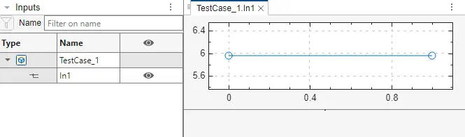
To open the Signal Editor dialog box and view the scenarios of signal sources, double-click the Inputs block. The Active scenario lists the test cases or counterexamples. To create and edit scenarios, launch the Signal Editor user interface. For more information, see Create and Edit Signal Data.
-
-
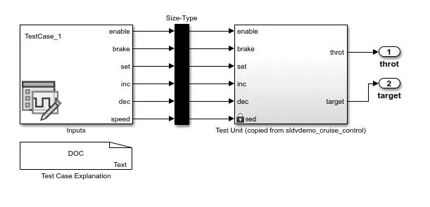
Size-Type — This Subsystem block transmits signals from the Inputs block to the Test Unit block. It verifies that the size and data type of the signals are consistent with the Test Unit block.
-
Test Unit — This Model block references the original model that Simulink Design Verifier analyzed.
If you do not select the Reference input model in generated harness on the Design Verifier > Results pane in the Configuration Parameters dialog box, the Test Unit created is a Subsystem block.
If the Test Unit in the harness model is a subsystem, the values of the parameters on the Optimization and Math and Data Types panes might impact the coverage results.
-
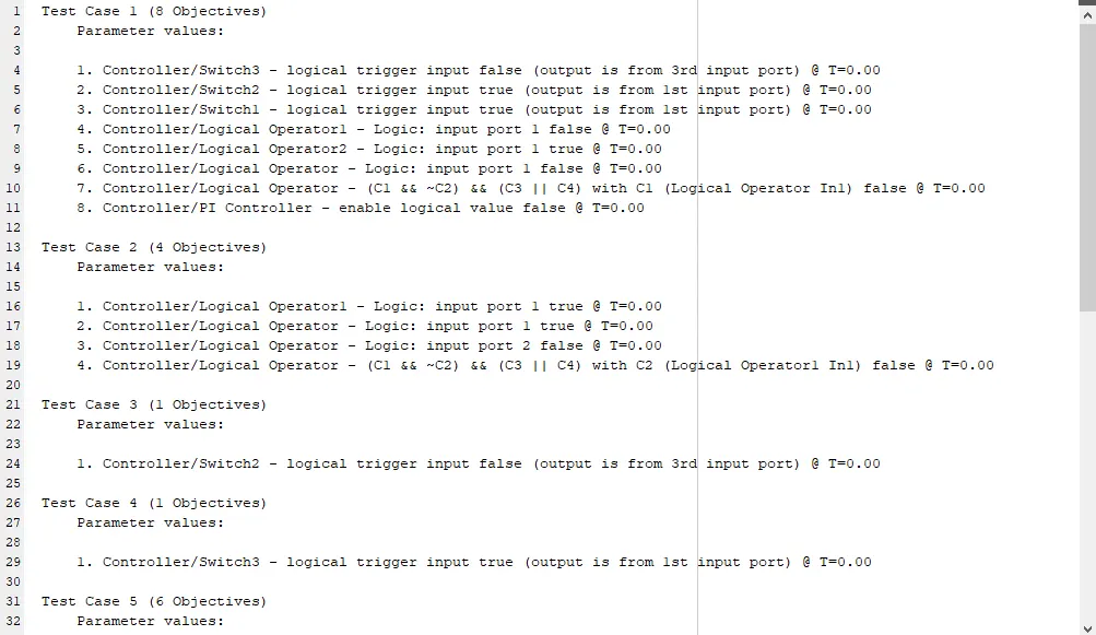
Test Case Explanation — This DocBlock block documents the test cases or counterexamples that Simulink Design Verifier generates. To view the description of each test case or counterexample, double-click the Test Case Explanation block. The block lists either the test objectives that each test case achieves or the proof objectives that each counterexample falsifies.
Configuration of the Harness Model
Simulink Design Verifier generates the harness model with these settings.
-
The harness model start time is always
0. If the original model uses a nonzero start time, the software ignores the start time and uses0for the simulation start time for test cases and counterexamples. -
The harness model stop time always equals the stop time of the longest test case in the Inputs block.
-
By default, the software enables coverage analysis and generates a coverage report for the harness models that contain test cases. The coverage reporting is enabled with default options. You can customize these settings by using Specify Coverage Options (Simulink Coverage).
-
By default, if you select Ignore objective based on filter and provide a coverage filter file for the Test Unit, the coverage filter file applies to the harness model. For more information, see Coverage data.
-
For models that use the complex type Inport block, a Signal Editor block is used as the harness source regardless of the Harness source that you specify.
Simulate the Harness Model
The harness model enables you to simulate a copy of your original model by using the test cases or counterexamples that Simulink Design Verifier generates. Using the harness model, you can simulate:
-
A counterexample.
-
A single test case, for which the Simulink Coverage™ software collects and displays model coverage information.
-
All the test cases, for which the Simulink Coverage software collects and displays cumulative model coverage information.
- he “coulomb counting” or CoulCount method was developed by Schmitt et al. as a heuristic method, although the underlying theory is reasonably accessible. It depends on the recording of the current noise only. The signal is filtered with a high-pass filter with a cut-off frequency of 0.01 Hz.