Week 7 State of charge estimation
AIM:-
1.Simulate the 3 test cases from harness dashboard and write a detailed report on the results.
Expaination:-
After downloading the zip file we first have to extract the zip file to a folder and then I choose again Battery_System_R2019a to extract to a a folder.
Then to get access to the Close Loop BMS harness dashboard we have to check for the following model Test>System>BMS_ClosedLoop_Harness_Dashboard model file.After opening this file Matlab will ask the following question:-
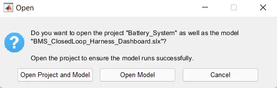
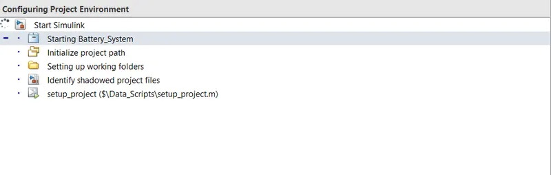
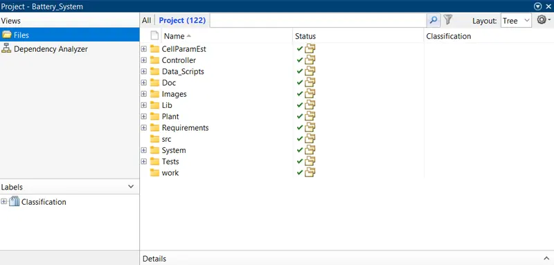
I have selected to Open Project and Model. ANd after that the whole project will be loaded in the Matlab in current folder and workkspace.
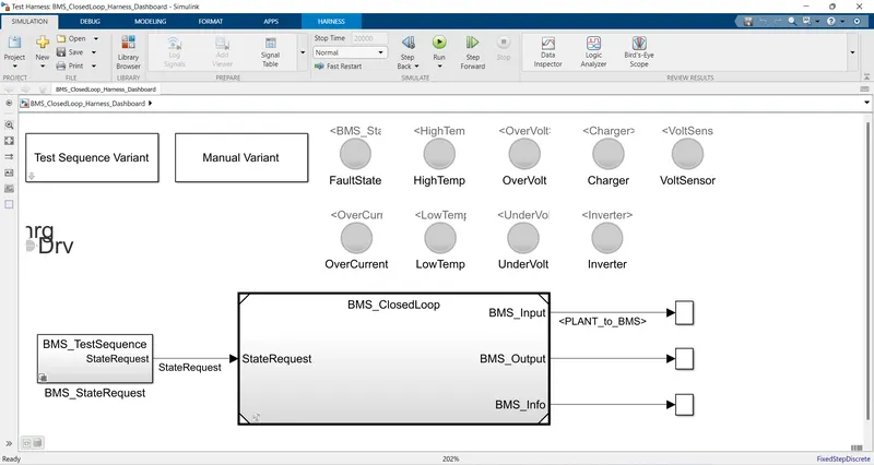
Block of Model:-
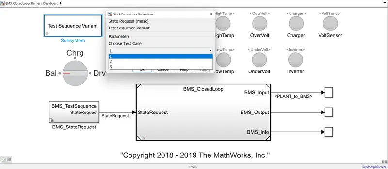
- Test sequence Variant (it has 3 different test condition)
- Manual Variant (selection)
- BMS_StateRequest subsytem to provide the state request commands.
- Indictaing lamps are there to show any fault state, High Temp, Overvoltage, Charger, Voltage Sensor, Overcurrent, Low temp, Under Voltage, Inverter state of a battery. Green light tell us that all states are Ok and battery is good to charge and discharge and red indication will indicate the fault state.
- Rotating switch for manual variant to change the position during simulation run time
- BMS_Closed Loop:- this subsystem contain BMS ECU and Plant as two main subsytem and lets see this block in details:-
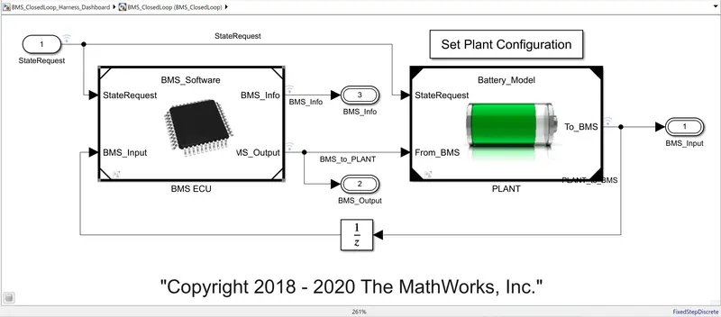
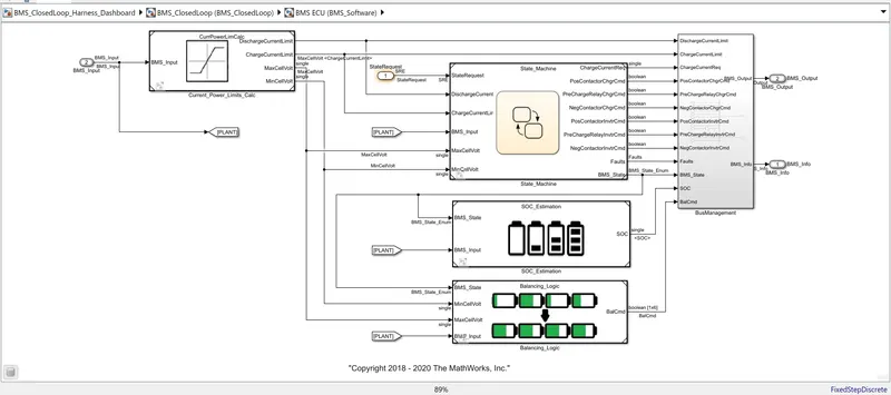
BMS ECU:- The BMS ECU get have two input which are BMS_Input which is feedaback from the Plant model and The state Request is coming from the state machine . This is generating output as BMS Output and Info which have current power limit calculation in State Machine, SOC estimation and Cell balancing logic as shown in screenshot upper cases.
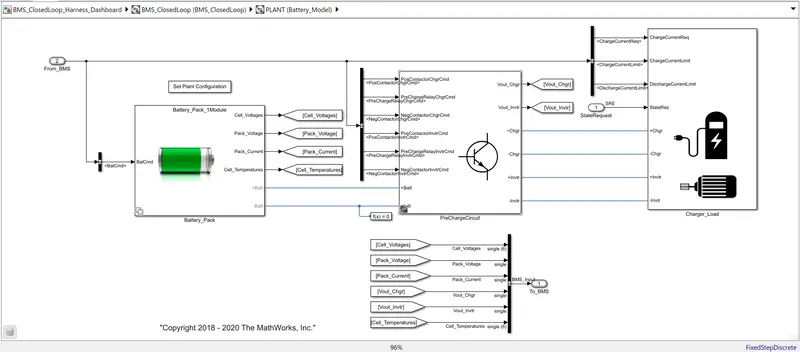
Plant:- This subsytem contain Battery pack, precharge circuit and charger / loads.In the battery pack there are two configuration which are 1 module (6 cells) and 16 module (96 cells).Here we have selected 1 module for simple calaulation and less simulation time.
3 Test Cases From Harness Dashboard :-
Test Case-1:-
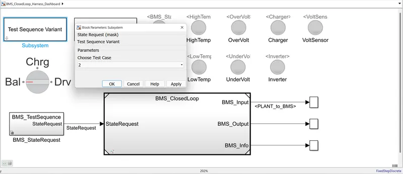
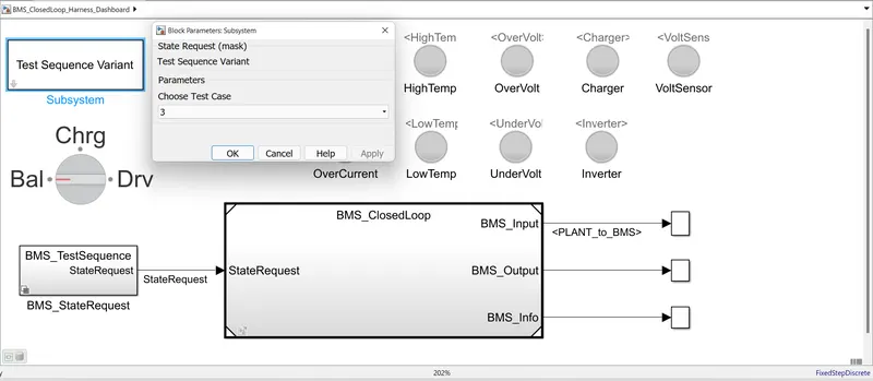
The test case 1 is selected as shown below in the dialog box and click OK to implement it.
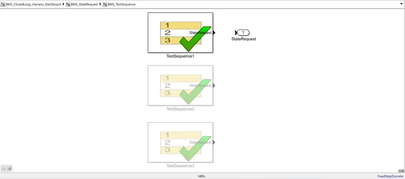
We can see the Test sequence in BMS_StateRequest>BMS_TestSequenec upper case.
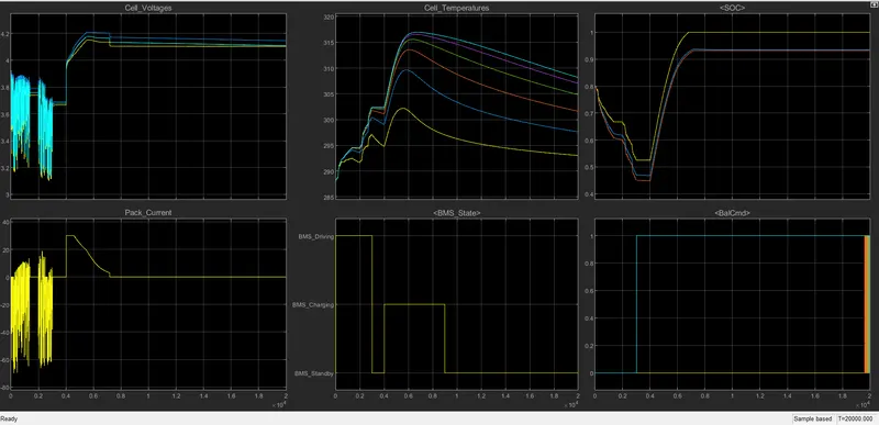
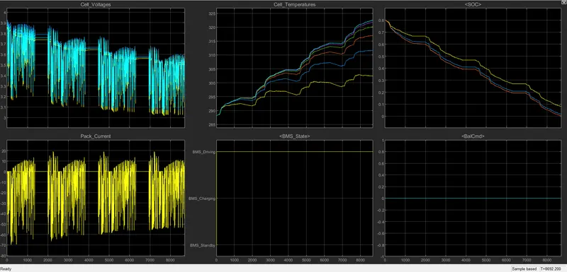
Results of Test Sequence 1:-
The Lamp indication were green for all states which means the model is fault free.
Test Case-2:-
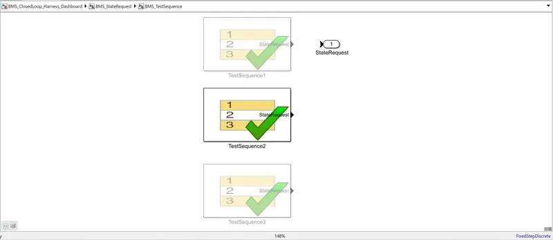
We can see the Test sequence in BMS_StateRequest>BMS_TestSequenece and there we can see that the test case we have selected is as shown below.
Results of Test Sequence 2:-
The Lamp indication were green for all states which means the model is fault free.
Test case- 3:-
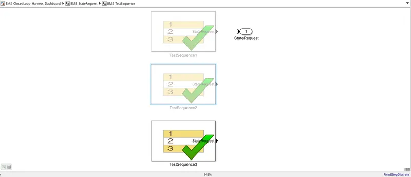
We can see the Test sequence in BMS_StateRequest>BMS_TestSequenece and there we can see that the test case we have selected is as shown below.
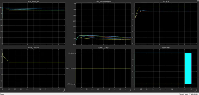
Results of Test Sequence 3:-
2.What is coulomb counting? Refer to the above model and explain how BMS implements coulomb counting for SOC estimation .
Coulomb Counting:-
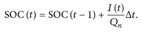
The Coulomb counting method measures the discharging current of a battery and integrates the discharging current over time in order to estimate SOC. Coulomb counting method is done to estimate the SOC(t) , which is estimated from the discharging current,I(t) , and previously estimated SOC values,SOC(t-1) .
SOC is calculated by the following equation:
But there are several factors that affect the accuracy of Coulomb counting method including temperature, battery history, discharge current, and cycle life
Modified Coulomb Counting Method:-
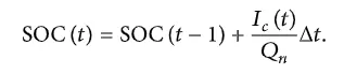
To improve the Coulomb counting method, a new technique called modified Coulomb counting method is proposed. The modified Coulomb counting method uses the corrected current to improve the accuracy of estimation. The corrected current is the function of discharging current. There is a quadratic relationship between the corrected current and discharging current of battery. By practice of experimental data, corrected current is calculated by the following form:

where k2 , k1 and k0 are constant values obtained from the practice experimental data.
In modified Coulomb counting method, SOC is calculated by the following equation:
SOC estimation in Battery model:-
To observe the coulomb counting method we need to open the BMS_ClosedLoop>BMS ECU and then on SOC_ Estimation block.
Here we see that there are three method for calculation of SOC estimation and these are:-
- Coulomb counting
- Unscented Kalman filter
- Extended laman filter.
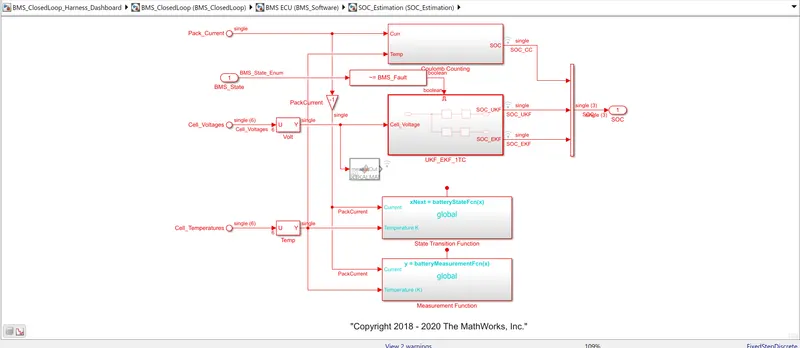
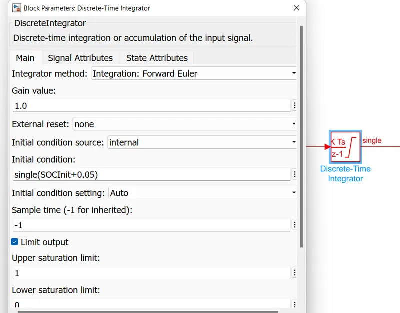
That current is divided by the capacity due to temperature change and then intregrated with the gain value of -1 wo=ith sample time of -1 as discrete type integrator is used here.