Week 7 State of charge estimation
1.Simulate the 3 test cases from harness dashboard and write a detailed report on the results.
Ans) Initially open the link in the question and download the neccessary files---->Later open the BMS closed loop harness file in simulink and run the simulations for all three test cases of driving standby and charging scenario.The battery harness dashboard is as represented below.
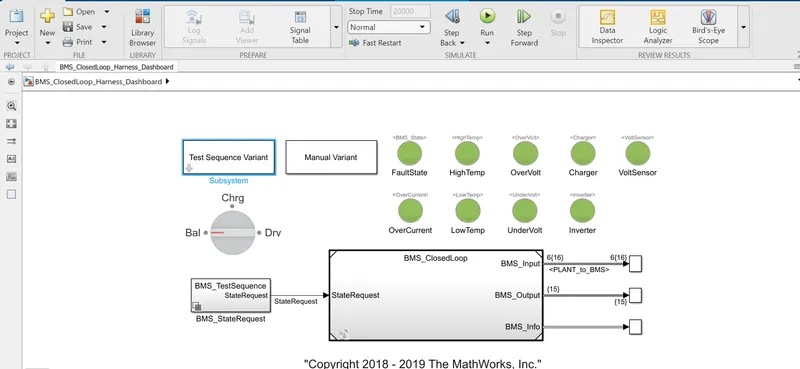
The above setup is such that a battery pack with a certain number of cells paired with a BMS is given commands of charging, discharging and standby and we can observe certain parameters like SOC,voltage, current etc of induvidual cells(some parameters) or collective pack details(some parameters)
Also observe the green lights on the model.Theyy indicate theres's no fault in the respective factors mentioned below them.
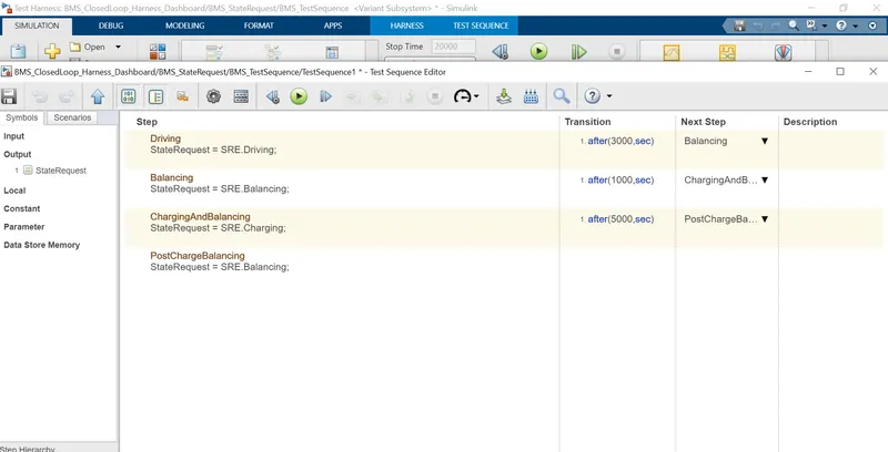
The different test cases are as below:
CASE1:
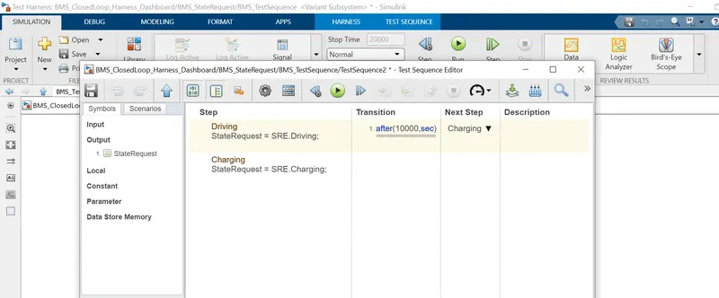
CASE2:
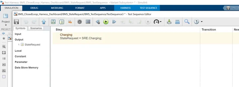
CASE3:
After running simulations of diiferent state requests over a period of time in each case the following graphs were obtained.
For CASE1:
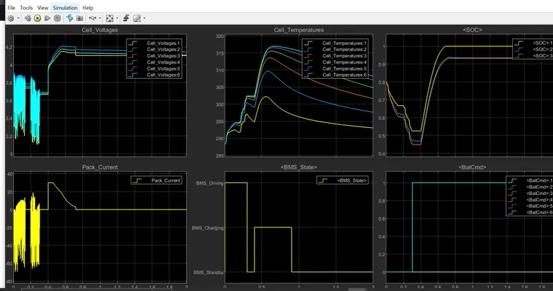
OBSERVATION
- We can see that initially the battery is used for driving(driving state) and as per the drive cycle there is variation in cell voltage and collecctive pack current.
- After some time,The cells/battery is in standby for a very short time period during which there is no big change in terms of SOC,CURRENT ,VOLTAGE even temperature.
- Later the battery is in charge mode and naturally we seecell voltage rising upto 4.2v and the over all pack current too.The SOC also reaches upt95% altogether.In the end pahse of standby/balancing theres not much change in any of the factors and its more likely a stable straight line till the end of simulation.
- It is observable tha t temperature rises significantly during driving and is not reduced much or in fact remains almost same during charging phase.
For CASE2:
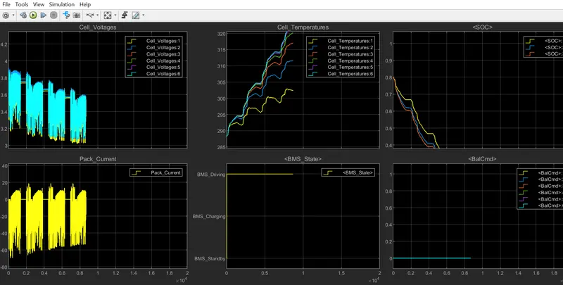
OBSERVATIONS
- In this case there sare two phases Driving for 10000s and then charging .But from the above graph it is seen that the battery is completely dicharged before completing 10000s.SOC IS 0% at roughly 8000s itself Hence charging scenario dosent take place in the simulation.A fault has occured.So even even when charging phase started there;s no change in the SOC.
For CASE3:
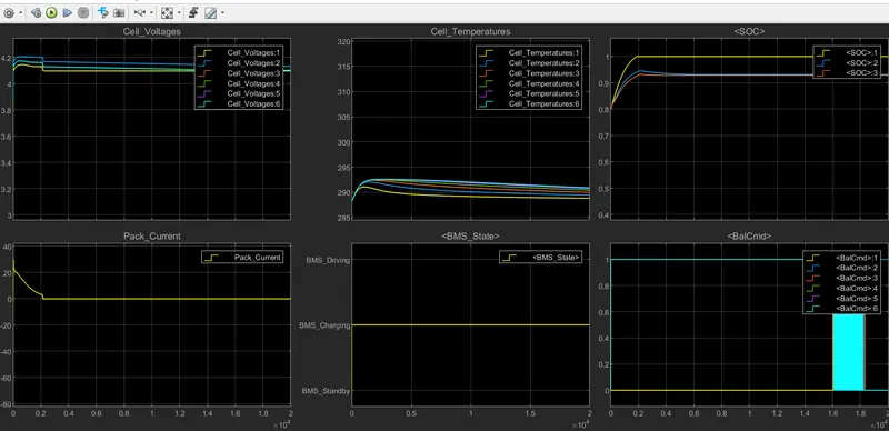
OBSERVATIONS
- Here there's only charging done for the entire simulation time.So cell voltage is aroung 4.1 through out and since there's no current used for driving it is at 0 throughout and the state of charge remains at a 100% after an initial rise.
2.What is coulomb counting? Refer to the above model and explain how BMS implements coulomb counting for SOC estimation ?
ans) Coloumb Counting
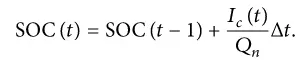
The Coulomb counting method measures the discharging current of a battery and integrates the discharging current over time in order to estimate SOC [20]. Coulomb counting method is done to estimate the SOC , which is estimated from the discharging current,I(t) , and previously estimated SOC values,SOC(t-1) . SOC is calculated by the following equation:

But there are several factors that affect the accuracy of Coulomb counting method including temperature, battery history, discharge current, and cycle life .
Modified coloumb counting method
To improve the Coulomb counting method, a new technique called modified Coulomb counting method is proposed. The modified Coulomb counting method uses the corrected current to improve the accuracy of estimation.
The corrected current is the function of discharging current. There is a quadratic relationship between the corrected current and discharging current of battery. By practice of experimental data, corrected current is calculated by the following form:

wherek2 , k1 and k0 are constant values obtained from the practice experimental data.
In modified Coulomb counting method, SOC is calculated by the following equation:
The experimental results show that the accuracy of the modified Coulomb counting method is superior to the conventional Coulomb counting method.
Inthe model we can see that as we go through the subsytems of SOC estimation----> columb counting----->we arrive at a simulink mode of the above formula to determijn SOC using Coloumn counting method.
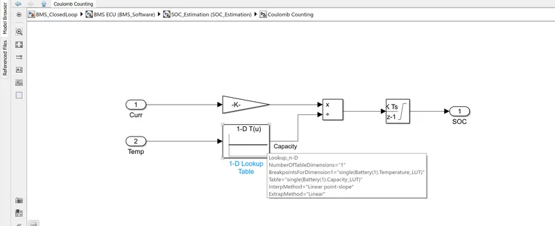
- This system does the estimation by coulomb counting equation mentioned above.
- Temperature and current from the battery is given as inputs.
- Current signal is given to a gain block and temperature is given to capacity since it varies according to temperature.
- These inputs are given for integration where current will be integrated with respect to time.
- This out is given to another block where it is divided by capacity.
- Hence the SOC is estimated.