Week 7 State of charge estimation
Results:-
Here all the indicators are green. So we can see no errors and we check the plot for this model which is shown below.
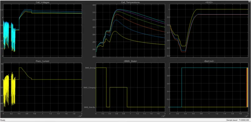
From the plot, we can see the vehicle is initially driving, and charging was done to 90%. After charging it reaches standby mode. It can be seen in the BMS state plot. Battery temperature increases in driving and charging. Battery voltage was increased to 4.2V while charging. The current plot shows the value of current supplied to the vehicle while driving. SOC decreased up to 50% in driving conditions and it was increased while charging.
2) Now change the test sequence variant in case two.
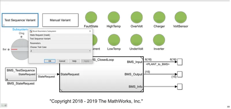
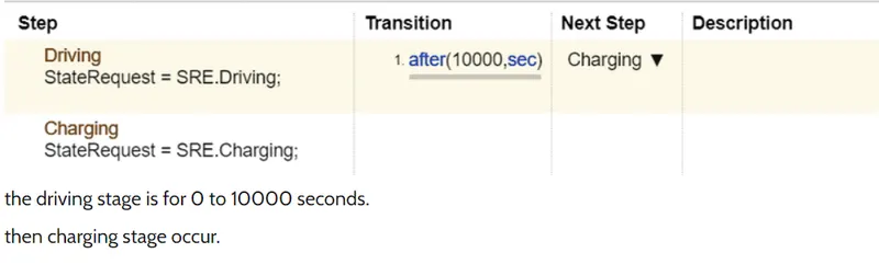
Now by clicking on the BMS state request block
Result:-
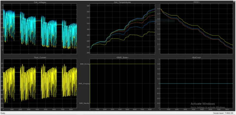
From the above graph, a fault condition occurred in the second case. So even after charging was started, the soc didn't increase. It continues to decrease.
3) Now by changing the test Sequence Value to 3
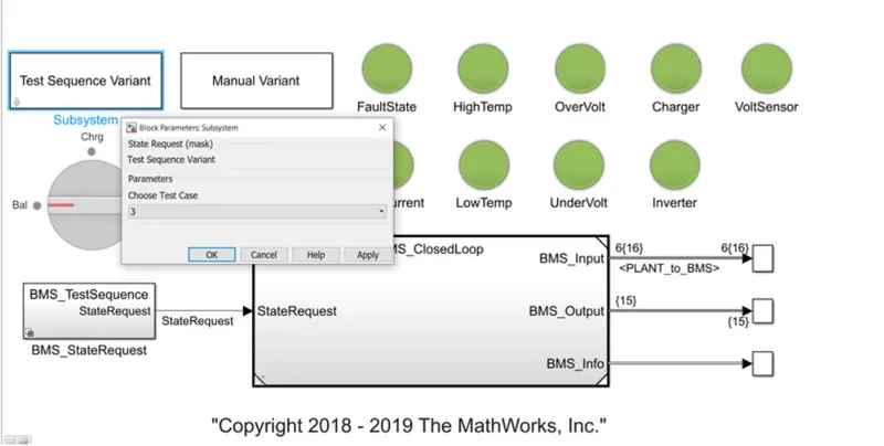

This condition has only one phase and that is charging. Thus 0 to 20000 seconds simulation runs.
Result:-
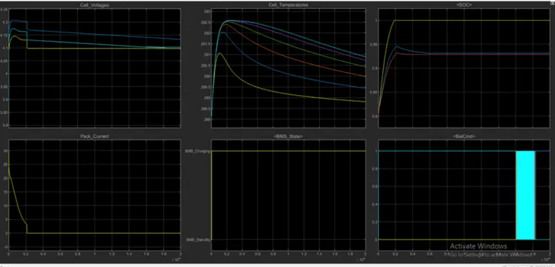
- Here we can see that the soc reached 100% in charging and remained in standby mode. Cell temperature also decreased when standby mode was achieved.
From the 3 cases we observe that only charging takes place thus SOC was 80% at first, then SOC increases to 100% in 2000 seconds then SOC remains constant at 100%.
2. What is coulomb counting? Refer to the above model and explain how BMS implements coulomb counting for SOC estimation?
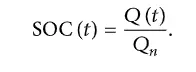
COULOMB COUNTING: The SOC is one of the most important parameters for batteries. In general, the SOC of a battery is defined as the ratio of its current capacity (Q(t))
to the nominal capacity (Qn). The nominal capacity is given by the manufacturer and represents the maximum amount of charge that can be stored in the battery.
The SOC can be defined as follows:
The various mathematical methods of estimation are classified according to methodology. The classification of these SOC estimation methods is divided into the following four categories.
(i)Direct measurement: this method uses physical battery properties, such as the voltage and impedance of the battery.
(ii)Book-keeping estimation: this method uses discharging current as the input and integrates the discharging current over time to calculate the SOC.
(iii)Adaptive systems: the adaptive systems are self-designing and can automatically adjust the SOC for different discharging conditions. Various new adaptive systems for
SOC estimation has been developed.
(iv)Hybrid methods: the hybrid models benefit from the advantages of each SOC estimation method and allow a globally optimal estimation performance. The literature shows that the
hybrid methods generally produce a good estimation of SOC, compared to individual methods.
Book-keeping estimation:
Book-keeping estimation method uses battery discharging current data as input. This method permits to include of some internal battery effects such as self-discharge, capacity-loss, and
discharging efficiency. Two kinds of book-keeping estimation methods have been employed: The coulomb counting method and the modified Coulomb counting method.
Coulomb counting method:
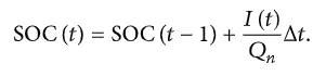
The Coulomb counting method measures the discharging current of a battery and integrates the discharging current over time to estimate SOC. Coulomb counting method
is done to estimate the SOC(t), which is estimated from the discharging current, I(t), and previously estimated SOC values, SOC(t).
SOC is calculated by the following equation:
But several factors affect the accuracy of the Coulomb counting method including temperature, battery history, discharge current, and cycle life.
Modified Coulomb counting method:
To improve the Coulomb counting method, a new technique called the modified Coulomb counting method is proposed. The modified Coulomb counting method uses the corrected current to
improve the accuracy of estimation.
The corrected current is the function of discharging current. There is a quadratic relationship between the corrected current and discharging current of the battery.
By the practice of experimental data, the corrected current is calculated in the following form:

where, k2, k1, and k0 are constant values obtained from the practice experimental data.
In the modified Coulomb counting method, SOC is calculated by the following equation:
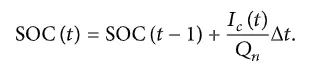
The experimental results show that the accuracy of the modified Coulomb counting method is superior to the conventional Coulomb counting method.
The SOC (state of charge) estimation model:
To see the SOC estimation model, we need open the different model blocks. The directions to open the SOC estimation module is, BMS_ClosedLoop >> BMS ECU >>SOC_Estimation >> Coulomb Counting.
With the help of the above-mentioned directions, we can open the SOC estimation model and coulomb counting model.
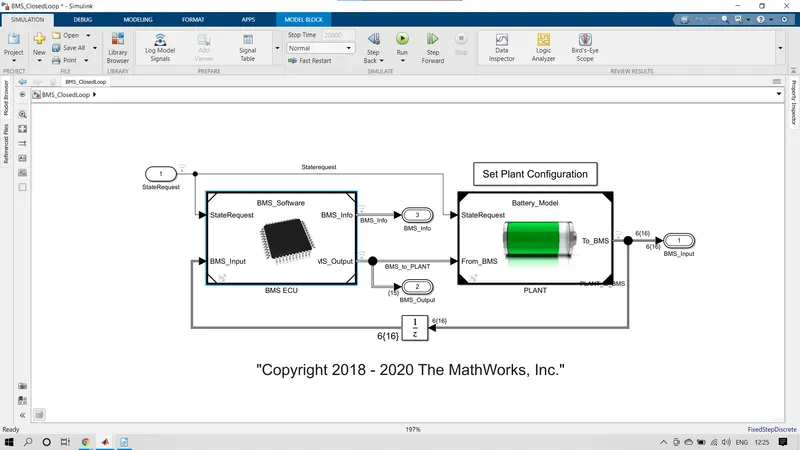
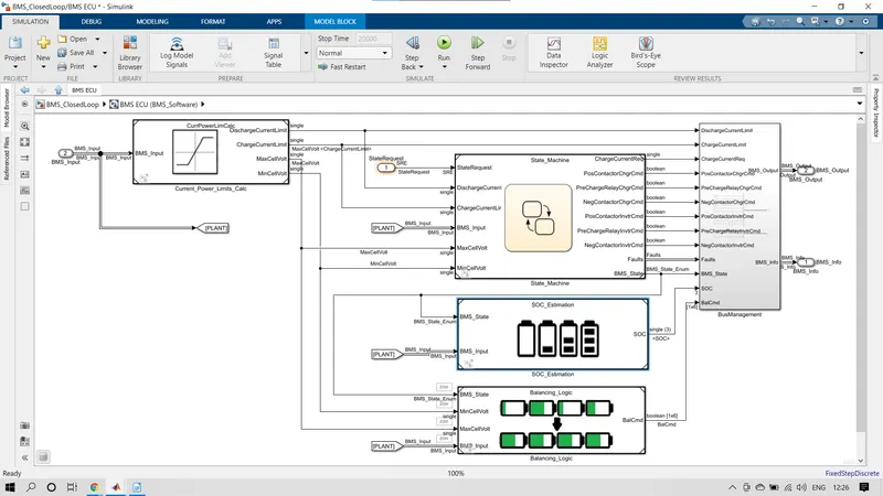
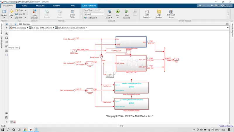
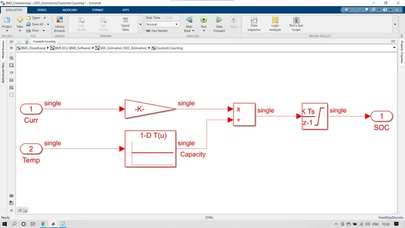
In the coulomb counting model, the pack current and temperature are the inputs for this model. The pack current is fed to the gain block with the value of 1/3600 to convert currencies into Amph hours. The temperature is fed to the 1-D lookup table to give the inputs to divide the block from the temperature input block. The Amp hour pack current and temperature get divided in the divided block and the output from the device block is connected to the Discrete-time integrator block to integrate the divided current and temperature signals. From the output of the discrete-time integrator block, we can get the desired final SOC (state of charge). The block parameters of the coulomb counting method are given below,
- Input signals [Pack Current and Temperature (k)]:
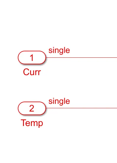
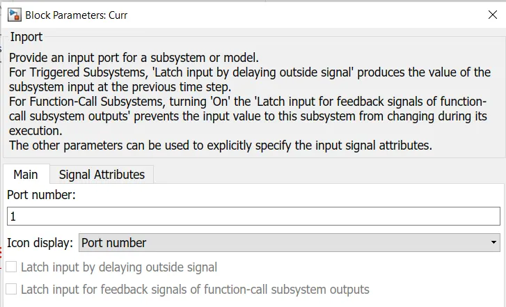
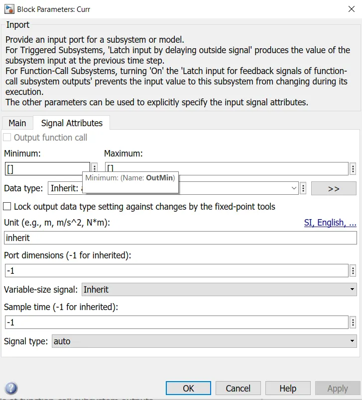
The input signals are fed to the coulomb counting model from other blocks in the project. the block parameters of pack current and temperature are
* Pack current:
* Temperature (k):
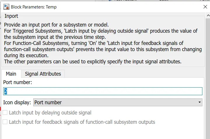
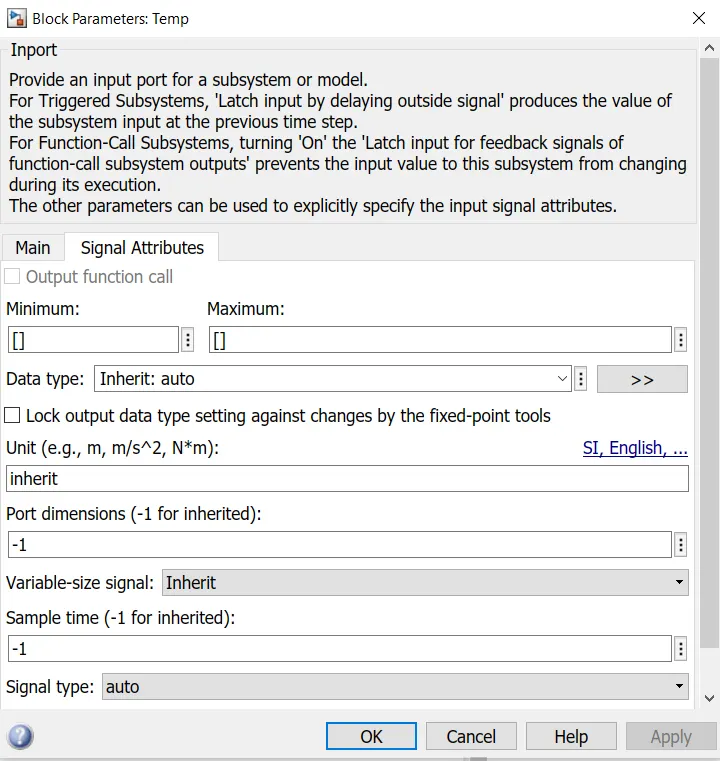
- Gain block:
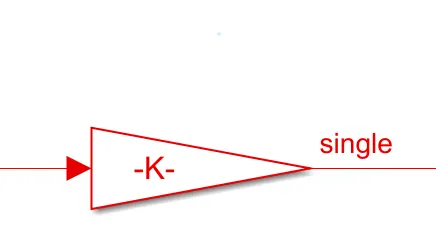
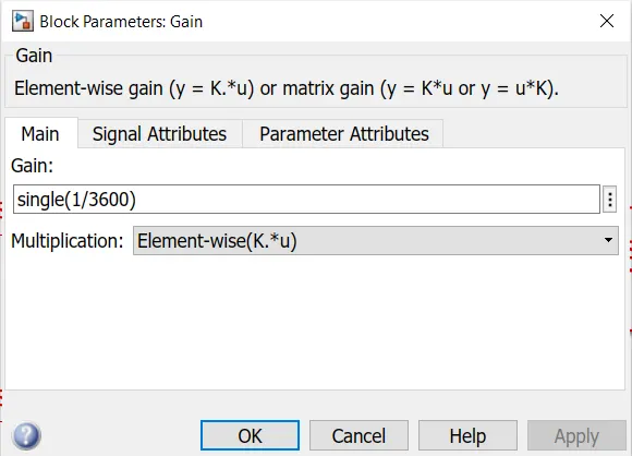
Here the discharge current from the battery is fed to the gain block with a value of 1/3600 to convert the current to 'Ahr'. The value is divided by capacity due to temperature change, then integrated with a gain value of 1 with sample time -1 as we are using a discrete integrator. The saturation limits are from 0 to 1. We will get the SOC values from 0 to 1 multiplied by 100 to get in the percentage of SOC.
- 1-D lookup table:
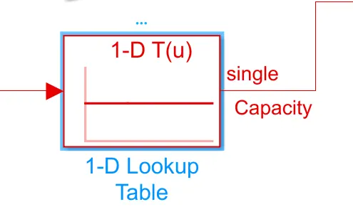
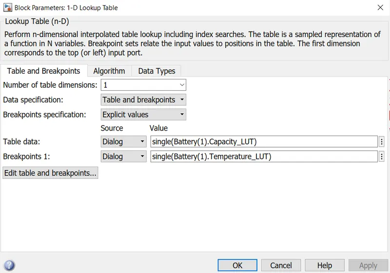
The 1-D lookup table is fed from the output of the temperature input block. The lookup table is used to give the input to divide the block.
Perform n-dimensional interpolated table lookup including index searches. The table is a sampled representation of a function in N variables. Breakpoint sets relate the input values to positions in the table. The first dimension corresponds to the top (or left) input port.
- Divide block:
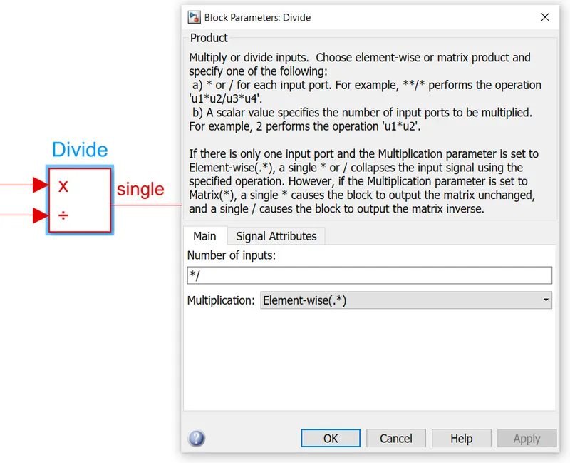
The dividing block gets the inputs from the gain block pack current to multiply the port and temperature from the 1-D lookup table to the divided port. the output from the divider block is fed to the discrete-time integrator block to integrate the divided pack current and temperature signals to get the SOC.
- Discrete-time integrator block:
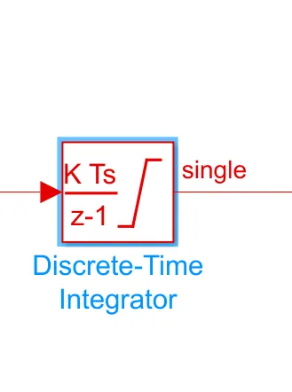
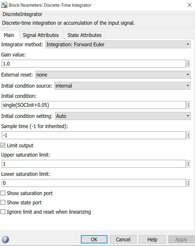
The integrator block gets the inputs from the divided block. The divided pack current and temperature values are integrated into the discrete-time integrator to get the desired final SOC ( state of charge). The output SOC from the integrator block is fed to the output block to visualize the SOC in the results graph.