Week 7 State of charge estimation
`color(teal)Acolor(blue)icolor(lime)m:-color(red)Scolor(blue)tcolor(orange)acolor(blue)tcolor(yellow)e color(black)ocolor(magenta)fcolor(indigo)Ccolor(pink)hcolor(orange)acolor(green)rcolor(lightgreen)gcolor(yellow)ecolor(aqua)Ecolor(brown)scolor(teal)tcolor(coral)icolor(maroon)mcolor(purple)acolor(violet)tcolor(coral)icolor(lime)ocolor(darkgreen)n`
Object:-
What is coulomb counting? How BMS implements coulomb counting for SOC estimation?
What is coulomb counting?
Coulomb counting
To determine available capacity, coulomb counting relies on the integration of the current drawn from and supplied to a battery over time, τ ∈`[t_0,t]`, as given by
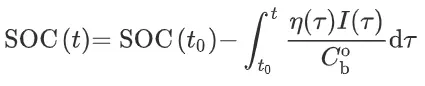
where I is the current and η is the efficiency during charge and discharge operations. Coulomb counting is advantageous in terms of a simple structure and its ease of implementation. However, some problems make it difficult to accurately estimate battery SOC by coulomb counting. Because battery capacity and efficiency are significantly influenced by operating temperature and current direction, these factors should be considered to correct for battery SOC. Sensor accuracy is also important because accumulated errors can lead to a drift in the estimated battery SOC. Furthermore, one of the main problems in coulomb counting is that it is necessary to calibrate the initial battery SOC. In several applications, the initialization involves rest and the initial SOC is estimated based on the voltage inversion method.
State of charge (SoC) is the level of charge of an electric battery relative to its capacity. The units of SoC are percentage points (0% = empty; 100% = full). An alternative form of the same measure is the depth of discharge (DoD), the inverse of SoC (100% = empty; 0% = full). SoC is normally used when discussing the current state of a battery in use, while DoD is most often seen when discussing the lifetime of the battery after repeated use.
Determining SoC
Usually, SoC cannot be measured directly but it can be estimated from direct measurement variables in two ways: offline and online. In offline techniques, the battery desires to be charged and discharged in constant rate such as Coulomb-counting. This method gives precise estimation of battery SoC, but they are protracted, costly, and interrupt main battery performance. Therefore, researchers are looking for some online techniques. In general there are five methods to determine SoC indirectly:
- chemical
- voltage
- current integration
- Kalman filtering
- pressure
Chemical method
This method works only with batteries that offer access to their liquid electrolyte, such as non-sealed lead acid batteries. The specific gravity or pH of the electrolyte can be used to indicate the SoC of the battery.
Hydrometers are used to calculate the specific gravity of a battery. To find specific gravity, it is necessary to measure out volume of the electrolyte and to weigh it. Then specific gravity is given by (mass of electrolyte [g]/ volume of electrolyte [ml])/ (Density of Water, i.e. 1g/1ml). To find SoC from specific gravity, a look-up table of SG vs SoC is needed.
More recently immersion refractometry has been shown to be a viable method for continuous monitoring of the state of charge. The refractive index of the battery electrolyte is directly relatable to the specific gravity or density of the electrolyte of the cell.
Voltage method
This method converts a reading of the battery voltage to SoC, using the known discharge curve (voltage vs. SoC) of the battery. However, the voltage is more significantly affected by the battery current (due to the battery's electrochemical kinetics) and temperature. This method can be made more accurate by compensating the voltage reading by a correction term proportional to the battery current, and by using a look-up table of battery's open circuit voltage vs. temperature.
In fact, it is a stated goal of battery design to provide a voltage as constant as possible no matter the SoC, which makes this method difficult to apply.
Current integration method
This method, also known as "coulomb counting", calculates the SoC by measuring the battery current and integrating it in time. Since no measurement can be perfect, this method suffers from long-term drift and lack of a reference point: therefore, the SoC must be re-calibrated on a regular basis, such as by resetting the SoC to 100% when a charger determines that the battery is fully charged (using one of the other methods described here).
Combined approaches
Maxim Integrated touts a combined voltage and charge approach that is claimed superior to either method alone; it is implemented in their ModelGauge m3 series of chips, such as MAX17050, which is used in the Nexus 6 and Nexus 9 Android devices.
Kalman filtering
To overcome the shortcomings of the voltage method and the current integration method, a Kalman filter can be used. The battery can be modeled with an electrical model which the Kalman filter will use to predict the over-voltage, due to the current. In combination with coulomb counting, it can make an accurate estimation of the state of charge. The strength of a Kalman filter is that it is able to adjust its trust of the battery voltage and coulomb counting in real time.
Pressure method
This method can be used with certain NiMH batteries, whose internal pressure increases rapidly when the battery is charged. More commonly, a pressure switch indicates if the battery is fully charged. This method may be improved by taking into account Peukert's law which is a function of charge/discharge rate or ampere.
How BMS implements coulomb counting for SOC estimation?
Battery management system
A battery management system (BMS) is any electronic system that manages a rechargeable battery (cell or battery pack), such as by protecting the battery from operating outside its safe operating area, monitoring its state, calculating secondary data, reporting that data, controlling its environment, authenticating it and / or balancing it.
A battery pack built together with a battery management system with an external communication data bus is a smart battery pack. A smart battery pack must be charged by a smart battery charger.
Monitor
A BMS may monitor the state of the battery as represented by various items, such as:
- Voltage: total voltage, voltages of individual cells, minimum and maximum cell voltage, or voltage of periodic taps.
- Temperature: average temperature, coolant intake temperature, coolant output temperature, or temperatures of individual cells.
- State of charge (SOC) or depth of discharge (DOD), to indicate the charge level of the battery.
- State of health (SOH), a variously-defined measurement of the remaining capacity of the battery as % of the original capacity.
- State of power (SOP), the amount of power available for a defined time interval given the current power usage, temperature and other conditions.
- State of Safety (SOS).
- Coolant flow: for air or fluid cooled batteries.
- Current: current in or out of the battery.
Electric vehicle systems: energy recovery
- The BMS will also control the recharging of the battery by redirecting the recovered energy (i.e.- from regenerative braking) back into the battery pack (typically composed of a few batteries, each composed of a few cells).
Thermal management[edit]
Battery thermal management systems can be either passive or active, and the cooling medium can either be air, liquid, or some form of phase change. Air cooling is advantageous in its simplicity. Such systems can be passive, relying only on the convection of the surrounding air, or active, utilizing fans for airflow. Commercially, the Honda Insight and Toyota Prius both utilize active air cooling of their battery systems. The major disadvantage of air cooling is its inefficiency. Large amounts of power must used to operate the cooling mechanism, far more than active liquid cooling.The additional components of the cooling mechanism also add weight to the BMS, reducing the efficiency of batteries used for transportation.
Liquid cooling has a higher natural cooling potential than air cooling as liquid coolants tend to have higher thermal conductivities than air. The batteries can either be directly submerged in the coolant or coolant can flow through the BMS without directly contacting the battery. Indirect cooling has the potential to create large thermal gradients across the BMS due to the increased length of the cooling channels. This can be reduced by pumping the coolant faster through the system, creating a tradeoff between pumping speed and thermal consistency.
Computation
Additionally, a BMS may calculate values based on the above items, such as:
- Maximum charge current as a charge current limit (CCL)
- Maximum discharge current as a discharge current limit (DCL)
- Energy [kWh] delivered since last charge or charge cycle
- Internal impedance of a cell (to determine open circuit voltage)
- Charge [Ah] delivered or stored (sometimes this feature is called Coulomb counter)
- Total energy delivered since first use
- Total operating time since first use
- Total number of cycles
Communication[edit]
The central controller of a BMS communicates internally with its hardware operating at a cell level, or externally with high level hardware such as laptops or an HMI.
High level external communication are simple and use several methods:
- Different types of serial communications.
- CAN bus communications, commonly used in automotive environments.
- Different types of Wireless communications.
Low voltage centralized BMSs mostly do not have any internal communications. They measure cell voltage by resistance divide.
Distributed or modular BMSs must use some low level internal cell-controller (Modular architecture) or controller-controller (Distributed architecture) communication. These types of communications are difficult, especially for high voltage systems. The problem is voltage shift between cells. The first cell ground signal may be hundreds of volts higher than the other cell ground signal. Apart from software protocols, there are two known ways of hardware communication for voltage shifting systems, Optical-isolator and wireless communication. Another restriction for internal communications is the maximum number of cells. For modular architecture most hardware is limited to maximum 255 nodes. For high voltage systems the seeking time of all cells is another restriction, limiting minimum bus speeds and losing some hardware options. Cost of modular systems is important, because it may be comparable to the cell price. Combination of hardware and software restrictions results to be a few options for internal communication:
- Isolated serial communications
- wireless serial communications
Protection
A BMS may protect its battery by preventing it from operating outside its safe operating area, such as:
Over-current (may be different in charging and discharging modes)
- Over-voltage (during charging), especially important for lead–acid and Li-ion cells
- Under-voltage (during discharging)
- Over-temperature
- Under-temperature
- Over-pressure (NiMH batteries)
- Ground fault or leakage current detection (system monitoring that the high voltage battery is electrically disconnected from any conductive object touchable to use like vehicle body)
The BMS may prevent operation outside the battery's safe operating area by:
- Including an internal switch (such as a relay or solid state device) which is opened if the battery is operated outside its safe operating area
- Requesting the devices to which the battery is connected to reduce or even terminate using the battery.
- Actively controlling the environment, such as through heaters, fans, air conditioning or liquid cooling
Optimization
In order to maximize the battery's capacity, and to prevent localized under-charging or over-charging, the BMS may actively ensure that all the cells that compose the battery are kept at the same voltage or State of Charge, through balancing. The BMS can balance the cells by:
- Wasting energy from the most charged cells by connecting them to a load (such as through passive regulators)
- Shuffling energy from the most charged cells to the least charged cells (balancers)
- Reducing the charging current to a sufficiently low level that will not damage fully charged cells, while less charged cells may continue to charge (does not apply to Lithium chemistry cells)
- Modular charging.
Battery Management System can use different methods to estimate the SOC of the battery, however one of the main ways used is the coulomb counting method. The BMS implements the coulomb counting method to measure the SOC using an algorithm which is shown in the below diagram:
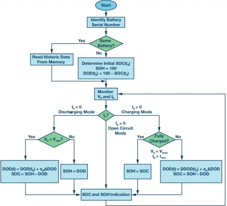
shows the flowchart of the enhanced coulomb counting algorithm. At the start, the historic data of the used battery is retrieved from the associated memory. Without any information for a newly used battery, the SOH is assumed to be healthy and has a value of 100%, and the SOC is initially estimated by testing either the open circuit voltage, or the loaded voltage depending on the starting conditions. The estimation process is based on monitoring the battery voltage (Vb) and Ib. The battery operation mode can be known from the amount and the direction of the operating current. The DOD is adding up the drained charge in the discharging mode and counting down with the
accumulated charge into the battery for the charging mode. After a correction with the charging and discharging efficiency, a more accurate estimation can be achieved. The SOC can be then estimated by subtracting the DOD quantity from the SOH one. When the battery is open circuited with zero current, the SOC is directly obtained from the relationship between the OCV and SOC.
It is noted that the SOH can be reevaluated when the battery is either exhausted or fully charged, and the battery operating current and voltage are specified by manufacturers. The battery is exhausted when the loaded voltage (Vb) becomes less than the lower limit (Vmin) during the discharging. In this case, the battery can no longer be used and should be recharged. At the same time, a recalibration to the SOH can be made by reevaluating the SOH value by the accumulative DOD at the exhausted state. On the
other hand, the used battery is fully charged if (Vb) reaches the upper limit (Vmax) and (Ib) declines to the lower limit (Imin) during charging. A new SOH is obtained by accumulating the sum of the total charge put into the battery and is then equal to SOC. In practice, the fully charged and exhausted states occur occasionally. The accuracy of the SOH evaluation can be improved when the battery is frequently fully charged and discharged. Thanks to the simple calculation and the uncomplicated hardware
requirements, the enhanced coulomb counting algorithm can be easily implemented in all portable devices, as well as electric vehicles. In addition, the estimation error can be reduced to 1% at the operating cycle next to the reevaluation of the SOH.
Initial SOC Determination
A battery can be operated at one of the three modes; charging, discharging, and open circuit. At the charging stage, the variations of the battery voltage and current when the battery is charged by the constant current, constant voltage (CC-CV) mode are usually specified by the manufacturer. With a constant charging current, the battery voltage increases gradually and reaches the threshold. Once the battery has been charged by the constant voltage mode, the charging current drops first rapidly, and then slowly. Eventually, the current declines to almost zero when it has been fully charged. This charging curve can be converted into the relationship between the SOC and the charging voltage during the constant current stage, and the relationship between the SOC and the charging current during the constant voltage stage. The initial SOC during charging can
be deduced from these relationships.
At the discharging stage, the typical voltage curves when the battery is discharged when different currents are given by the manufacturer. The terminal voltage declines as the operating time elapses. A higher current causes faster decline in the terminal voltage, leading to a shorter operation time. The relationship between SOC and the discharging voltage at different currents can then be obtained, and the initial SOC during the
discharging stage can be deduced. At the open circuit stage, the relationship between the OCV and the SOC is needed. The battery is discharged by different currents before
disconnecting from the load. The OCV can be used to estimate SOC if a long period rest time is available.