Week 7 - Simulation of a 1D Super-sonic nozzle flow simulation using Macormack Method
AIM:
To simulate the isentropic flow through a quasi 1D subsonic-supersonic nozzle.To solve the governing equations both in the conservation and non-conservation forms using MacCormack's technique.
OBJECTIVE:
- To determine the steady-state temperature distribution for the flow-field variables
- Investigate the difference between the two forms of governing equations by comparing their solutions.
- To plot,
- Steady-state distribution of primitive variables inside the nozzle
- Time-wise variation of the primitive variables
- Variation of Mass flow rate distribution inside the nozzle at different time steps during the time-marching process
- Comparison of Normalized mass flow rate distributions of both forms
- Perform a grid independence test on the solution
PROBLEM DESCRIPTION:
Consider a steady isentropic flow through a convergent divergent nozzle.The flow at the inlet to the nozzle comes from a reservoir where the pressure and the temperature are denoted by `P_0 and T_0`. The cross sectional area of the reservoir is large and hence the velocity is very small. Thus, `P_0 and T_0` are the stagnation values, or total pressure and total temperature.The flow expands isentropically to supersonic speed at the nozzle exit,where the temp, pressure,velocity and mach numeber are denoted by `T_e,P_e,V_e,M_e`.The flow is locally subsonic in the convergent region of the nozzle,sonic at the throat and supersonic at the divergent section.We assume that at a given section where the c/s area is A, the flow properties are uniform across the section. Althought the area of the nozzle changes w.r.t `x`, in reality the flow field is two dimensional.But we make the assumption that flow field varies along `x` which is equivalent in assuming that, across a given section, flow properties is uniform.Thus, the flow can be asssumed as quasi one dimensional flow.
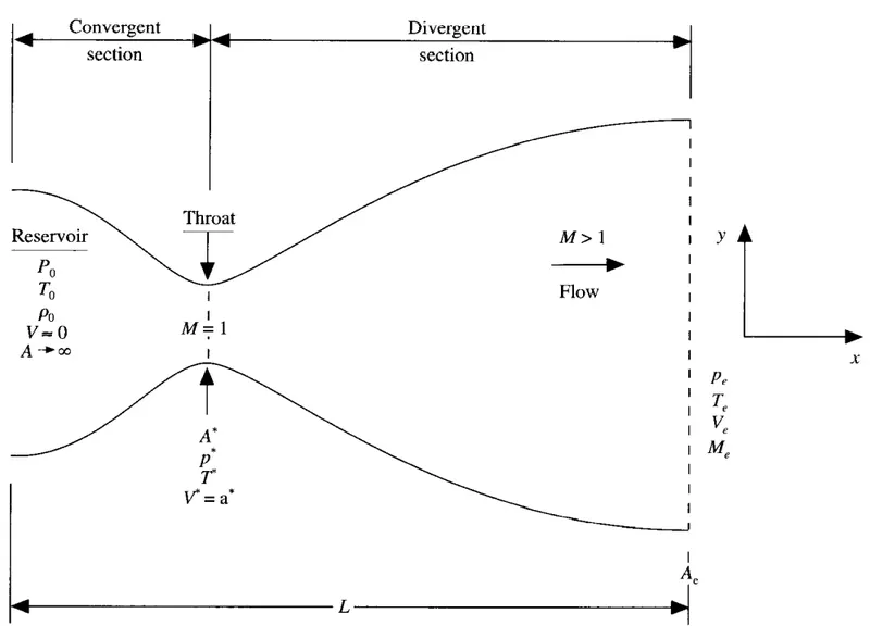
Fig.1: Schematic for subsonic-supersonic isentropic nozzle flow
Any numerical solution of isentropic flow though a quasi 1D subsonic-supersonic nozzle is unreasonable, while analytic solution exists for these kind of problems. However we are trying here to establish the broadened capability of CFD in various streams rather in representing the approximated form of anayltic solution. Here, we implement the numerical solution with Conservative and Non-Conservative forms.
Governing Equations are marched in terms of PDE for both forms in order to use Time Marching solution for the problem. These forms represent in numerical aspect only, if we analytic all the methods are same.
Non-Conservative form:
Continuity: `(delrho^')/(delt^') = -rho^'(delV^')/(delx^')-rho^'V^'(del (InA^'))/(delx^')-V^'(delrho^')/(delx^')`
Momentum: `(delV^')/(delt^')=-V^'(delV^')/(delx^')-(1/gamma)((delT^')/(delx^')+(T^'/rho^')(delrho^')/(delx^'))`
Energy: `(delT^')/(delt^')=-V^'(delT^')/(delx^')-(gamma-1)T^'[(delV^')/(delx^')+V^'(del(InA^'))/(delx^')]`
Conservative form:
Continuity: `(delrho^'A^')/(delt^')+(delrho^'A^'V^')/(delx^')=0`
Momentum: `(delrho'A'V')/(delt')+(del(rho'A'V'^2+(1/gamma)p'A'))/(delx')=(1/gamma)p'(delA')/(delx')`
Energy: `(del[rho'((T')/(gamma-1)+(gamma/2)V'^2)A'])/(delt')+(del[rho'((T')/(gamma-1)+(gamma/2)V'^2)p'V'A'])/(delx')=0`
For the nozzle flows the flow field variables are frequently expressed in terms of non dimensional variables.The non dimensional variables for the nozzle flow as expressed in the non conservative and conservative form of governing differential equatons are expressed below:
Non dimensional temperature and density: `T'=T/T_0 , rho'=rho/rho_0`,where `T_0 and rho_0`represent the temperature and density of the reservoir
Dimensionless length: `x'=x/L`,where L denotes the length of the nozzle
Dimensionless velocity: `V'=V/a_0`, where `a_0`is the speed of sound in the reservoir given by `a_0=sqrt(gammaRT_0)`
Dimensionless time: `t'=t/(L/a_0)`
Dimensionless area: `A'=A/A^(ast)`, where A is the local area and `A^ast`is the local throat area.
METHODOLOGY:
The governing equations both in conservative and non conservative form is solved using MacCormack's method.In particular, we will employ a time marching, finite difference solution for the quasi-one-dimensional nozzle flow.
First, we will discuss the MacCormack's method when applied to the non conservative form of governing equation for nozzle flow.Since, we implement a finite difference solution, we divide the `x`axis along the nozzle into a number of discrete points. The grid points of the nozzle is shown in Fig. 2.The point is assumed to be evenly distributed along `x`with `Deltax`being the spacing between the two grid points. Point `i`is an arbitraty grid point with points `i-1 and i+1`as the adjescent nodes.
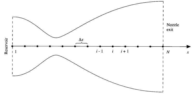
Fig.2: Grid point distribution along the nozzle
MacCormack's technique is a predictor-corrector method.First consider the preddictor step we have to set up the spatial derivative by forward differencing, and the corrector step employ backward differencing for spatial derivatives Note that, all the vaiables that we use in the following discretization is non dimensional.
Predictor step:
Continuity: `((delrho)/(delt))_i^t = -rho_i^t(V_(i+1)^t-V_i^t)/(Deltax)-rho_i^tV_i^t(In A_(i+1)-InA_i)/(Deltax)-V_i^t(rho_(i+1)^t-rho_i^t)/(Deltax)`
Momentum: `((delV)/(delt))_i^t=-V_i^t(V_(i+1)^t-V_i^t)/(Deltax)-(1/gamma)((T_(i+1)^t-T_i^t)/(Deltax)+(T_i^t/rho_i^t)(rho_(i+1)^t-rho_i^t)/(Deltax))`
Energy: `((delT)/(delt))_i^t=-V_i^t(T_(i+1)^t-T_i^t)/(Deltax)-(gamma-1)T_i^t(((V_(i+1)^t-V_i^t)/(Deltax))+V_i^t(InA_(i+1)-InA_i)/(Deltax))`
Thus, the predicted values of `rho,V,T`is obained as ;
`barrho_i^(t+Deltat)=barrho_i^t+((delrho)/(delt))_i^tDeltat`
`barV_i^(t+Deltat)=barV_i^t+((delV)/(delt))_i^tDeltat`
`barT_i^(t+Deltat)=barT_i^t+((delT)/(delt))_i^tDeltat`
Corrector step:
Continuity: `(bar(delrho)/(delt))_i^(t+Deltat) = -barrho_i^(t+Deltat)(barV_(i)^(t+Deltat)-barV_(i-1)^t)/(Deltax)-barrho_i^(t+Deltat)barV_i^(t+Deltat)(In A_(i)-InA_(i-1))/(Deltax)-barV_i^(t+Deltat)(barrho_(i)^(t+Deltat)-barrho_(i-1)^(t+Deltat))/(Deltax)`
Momentum: `(bar(delV)/(delt))_i^(t+Deltat)=-barV_i^(t+Deltat)(barV_(i)^(t+Deltat)-barV_(i-1)^(t+Deltat))/(Deltax)-(1/gamma)((barT_(i)^(t+Deltat)-barT_(i-1)^(t+Deltat))/(Deltax)+(barT_i^(t+Deltat)/barrho_i^(t+Deltat))(barrho_(i)^(t+Deltat)-barrho_(i-1)^(t+Deltat))/(Deltax)`
Energy:`(bar(delT)/(delt))_i^(t+Deltat)=-barV_i^(t+Deltat)(barT_(i)^(t+Deltat)-barT_(i-1)^(t+Deltat))/(Deltax)-(gamma-1)barT_i^(t+Deltat)(((barV_(i)^(t+Deltat)-barV_(i-1)^(t+Deltat))/(Deltax))+barV_i^(t+Deltat)(InA_(i)-InA_(i-1))/(Deltax))`
The average time derivatives are given by:
`((delrho)/(delt))_(av)=0.5[((delrho)/(delt))_i^t+(bar(delrho)/(delt))_i^(t+Deltat)]`
`((delV)/(delt))_(av)=0.5[((delV)/(delt))_i^t+(bar(delV)/(delt))_i^(t+Deltat)]`
`((delT)/(delt))_(av)=0.5[((delT)/(delt))_i^t+(bar(delT)/(delt))_i^(t+Deltat)]`
Now the corrected values of the flow field variables at time `t+Deltat`
Density: `rho_i^(t+Deltat)=rho_i^t+((delrho)/(delt))_(av)Deltat`
Velocity: `V_i^(t+Deltat)=V_i^t+((delV)/(delt))_(av)Deltat`
Temperature: `T_i^(t+Deltat)=T_i^t+((delT)/(delt))_(av)Deltat`
In a similar approach, the conservative form of the governing equation can be solved using MacCormack's method with predictor and corrector.
SOLUTION:
Inorder for the code to be modular, the code is split into three parts.
- Main program
- Function for Conservative form
- Function for Non-conservative form
Main Program:
close all
clear all
clc

%Length of nozzle
L=3;

%Number of grid points
n=[31 62 93 124 155];

%Number of time steps
nt=1:1400;

%CFL number
cfl = 0.5;

for i = 1:length(n)
x=linspace(0,L,n(i));
[mf_nc,mf_throat_nc]=non_conservative1(L,n(i),nt,cfl);
[mf_c,mf_throat_c]=conservative1(L,n(i),nt,cfl);

figure(7)
subplot(2,1,1)
plot(nt,mf_throat_c,'b',nt,mf_throat_nc,'r','linewidth',1)
xlabel('Time steps (nt)')
ylabel('Mass flow rate')
legend('Conservative form','Non-Conservative form')
title('Mass flow rate using "Non-Conservative form vs Conservative form" at throat point i=16')

subplot (2,1,2)
plot(x,mf_c,'b',x,mf_nc,'r','linewidth',1)
xlabel('Length of nozzle')
ylabel('Mass flow rate')
legend('Conservative form','Non-Conservative form')
title('Mass flow rate using "Non-Conservative form vs Conservative form" in the nozzle')

figure(8)
subplot (2,1,1)
plot(nt,mf_throat_c,'linewidth',1)
hold on
xlabel('Time steps (nt)')
ylabel('Mass flow rate')
legend('31 nodes','62 nodes','93 nodes')
title('Conservative form: Grid independency test at throat point i=16')

subplot (2,1,2)
plot(nt,mf_throat_nc,'linewidth',1)
hold on
xlabel('Time steps (nt)')
ylabel('Mass flow rate')
legend('31 nodes','62 nodes','93 nodes','124 nodes','155 nodes')
title('Non-Conservative form: Grid independency test at throat point i=16')

figure(9)
subplot (2,1,1)
plot(x,mf_c,'linewidth',1)
hold on
xlabel('Length of nozzle')
ylabel('Mass flow rate')
legend('31 nodes','62 nodes','93 nodes','124 nodes','155 nodes')
title('Conservative form: Grid independency test along the nozzle')

subplot (2,1,2)
plot(x,mf_nc,'linewidth',1)
hold on
xlabel('Length of nozzle')
ylabel('Mass flow rate')
legend('31 nodes','62 nodes','93 nodes','124 nodes','155 nodes')
title('Non-Conservative form: Grid independency test along the nozzle')
end
Explanation:
- Input parameters were given for the variables x, dx, n, gamma, nt and cf1.
- Non Conservative and Conservative forms are created as separate functions with the neccessary inputs.
- Plotting is done for the following solutions
1)Timestep variation at throat area of both forms
2)Variation of Flow Rate Distribution of both forms
3)Comparison of Normalized Mass Flow Rate of both forms - Each plot is computed as subplots of four primitive variables such as Density, Temperature, Pressure and Mach Number at throat as well as Convergent/Divergent section.
Function for Non-conservative form:
%   FUNCTION FOR NON-CONSERVATIVE FORM OF GOVERNING EQUATION
function [mf_nc,mf_throat_nc]=non_conservative1(L,n,nt,cfl)
L=3;
x=linspace(0,L,n);
dx=x(2)-x(1);

% initial conditions rho, a, v, T, mf, M, p
rho = 1-0.3146*x;
T= 1-0.2314*x;
v=(0.1+1.09*x).*T.^0.5;
a= 1+2.2*(x-1.5).^2;
M= v./(T.^0.5);
mf = rho.*a.*v;
p=rho.*T;

g = 1.4;

for z=1:31
    u=(T(z))^(1/2);
    dt(z) = cfl*dx/(u + v(z));
end
dt=min(dt);

for i = 1:length(nt)
  %Saving a copy of old values
    rho_old = rho;
    T_old = T;
    v_old = v;
    %Predictor step
   for j=2:n-1
    drho_dx = (rho(j+1)-rho(j))/dx;
    dv_dx = (v(j+1)-v(j))/dx;
    dT_dx = (T(j+1)-T(j))/dx;
    da_dx = (log(a(j+1))-log(a(j)))/dx;
    %Continuty
    drho_dt_p(j) = -rho(j)*dv_dx - rho(j)*v(j)*da_dx - v(j)*drho_dx;
    %Momentum
    dv_dt_p(j) = -v(j)*dv_dx - (1/g)*(dT_dx + (T(j)/rho(j))*drho_dx);
    %Energy
    dT_dt_p(j) = -v(j)*dT_dx - (g-1)*T(j)*(dv_dx + v(j)*da_dx);

   %Updating primitives
    v(j) = v_old(j) + dv_dt_p(j)*dt;
    rho(j) = rho_old(j) + drho_dt_p(j)*dt;
    T(j) = T_old(j) + dT_dt_p(j)*dt;

    %Corrector step
    drho_dx = (rho(j)-rho(j-1))/dx;
    dv_dx = (v(j)-v(j-1))/dx;
    dT_dx = (T(j)-T(j-1))/dx;
    da_dx = (log(a(j))-log(a(j-1)))/dx;

    %Continuity
    drho_dt_c(j) = -rho(j)*dv_dx - rho(j)*v(j)*da_dx - v(j)*drho_dx;
    %Momentum
    dv_dt_c(j) = -v(j)*dv_dx - (1/g)*(dT_dx + (T(j)/rho(j))*drho_dx);
    %Energy
    dT_dt_c(j) = -v(j)*dT_dx - (g-1)*T(j)*(dv_dx + v(j)*da_dx);
  end

  %Average time derivatives
    drho_dt_avg = 0.5*(drho_dt_p + drho_dt_c);
    dv_dt_avg = 0.5*(dv_dt_p + dv_dt_c);
    dT_dt_avg = 0.5*(dT_dt_p + dT_dt_c);

  %Final corected values
  for k = 2:n-1
    rho(k) = rho_old(k) + drho_dt_avg(k)*dt;
    v(k) = v_old(k) + dv_dt_avg(k)*dt;
    T(k) = T_old(k) + dT_dt_avg(k)*dt;
  end

  %Inlet boundary conditions
    v(1) = 2*v(2)-v(3);
  %Exit boundary conditions
    v(n) = 2*v(n-1)-v(n-2);
    rho(n) = 2*rho(n-1)-rho(n-2);
    T(n) = 2*T(n-1)-T(n-2);
  %Final update of primitives
    p = rho.*T;
    M= v./T.^0.5;
    error(k) =  abs(v(k)-v(k-1));
    mf= rho.*a.*v;
  %Finding values at throat point
    T_throat(i) = T(16);
    rho_throat(i) = rho(16);
    v_throat(i) = v(16);
    M_throat(i) = M(16);
    p_throat(i) = p(16);
    error_throat(i)=error(16);
    mf_throat(i)=mf(16);
    if n==31
for ii=[1:50:201 700]
    if ii==i
       figure(1)
     plot(x,mf,'linewidth',1)
     hold on
     title ('Non-Conservative form - Variation of Mass flow rate distribution inside the nozzle at different time steps during the time-marching process')
     xlabel('Length of nozzle')
     ylabel('Mass flow rate')
    elseif i==1400
     plot(x,mf,'*r')
     legend('1','51','101','151','201','700','1400')
    end
end
end

end
if n==31
figure(2)
     plot(x,v,'b',x,p,'r',x,T,'k',x,rho,'m',x,M,'g',x,mf,'c')
     ylim([-0.1 3.7])
     title (sprintf('Time step = %d',i))
     xlabel('Length of nozzle')
     ylabel('Non dimensional parameters')
     legend('Velocity','Pressure','Temperature','Density','Mach number','Mass flow rate','location','northwest')
     title('Non-Conservative form - Steady-state distribution of primitive variables inside the nozzle')

figure (3)
plot(nt,rho_throat)
hold on
plot(nt,v_throat,'linewidth',1)
plot(nt,p_throat,'linewidth',1)
plot(nt,T_throat,'linewidth',1)
plot(nt,M_throat,'linewidth',1)
plot(nt,mf_throat,'linewidth',1)
xlabel('Time steps (nt)')
ylabel('Non dimensional parameters')
legend('Density','Velocity','Pressure','Temperature','Mach number','Mass flow rate')
title('Non-Conservative form - Time-wise variation of the primitive variables at throat point i=16')
end
mf_nc=mf;
mf_throat_nc=mf_throat;
end
Explanation:
- The purpose of the function is to calculate the values of
Mass flow rate, Pressure, Mach number, Density, velocity, Temperature, Density at throat, velocity at throat, Temperature at throat, Mass flow rate at throat, Pressure at throat, Mach number at throat by the known equations for all the grid points in the non conservative form of the equation - For this initial profiles for the Density, Temperature, Velocity and area of the nozzle has been defined.
- Outer Time loop is executed, to calculate all the grid points for various formulas inside the loop.
- MacCarmack technique is used to solve the numerical solution of governing equations such as Continuity, Momentum & Energy Equation.
- Predictor, Corrector method is employed to solve the equations
- Predictor & Corrector method are assigned within the for loop individually for calculating values.
- The calculated values are averaged in the next step and updating the solution with old values.
- Boundary Conditions are applied within the for loop and subsequently used for calculating the Mass Flow Rate, Mach Number & Pressure and also calculating the values throat section.
- Finally plotting is done for Distance(x) & Mass Flow Rate for differrent Timesteps.
Function for Conservative form:
%   FUNCTION FOR CONSERVATIVE FORM OF GOVERNING EQUATION
function [mf_c,mf_throat_c]=conservative1(L,n,nt,cfl)
L=3;
x=linspace(0,L,n);
dx=x(2)-x(1);

% initial conditions rho, a, v, T, M, mf, p
for i=1:length(x)
    if (x(i)<=0.5)
        rho(i) = 1;
        T(i) = 1;
    elseif (x(i)>0.5) & (x(i)<=1.5)
        rho(i) = 1-0.366*(x(i)-0.5);
        T(i)= 1-0.167*(x(i)-0.5);
    elseif (x(i)>1.5) & (x(i)<=3.5)
        rho(i) = 0.634-0.3879*(x(i)-1.5);
        T(i)= 0.833-0.3507*(x(i)-1.5);
    end
end
a= 1+2.2*(x-1.5).^2;     %area
g = 1.4;                 %gamma value
% solution vectors u1, u2, u3
u1 = rho.*a;
u2 = 0.59*ones(1,n);
v=u2./u1;
u3 = u1.*((T./(g-1))+(g/2).*v.^2);

M= v./(T.^0.5);          %Mach number
mf = rho.*a.*v;          %Mass flow rate
p=rho.*T;                %Pressure

%Time step control
for z=1:31
u=(T(z))^(1/2);
dt(z) = cfl*dx/(u + v(z));
end
dt=min(dt);

for i = 1:length(nt)
    %Saving a copy of old values
    u1_old = u1;
    u2_old = u2;
    u3_old = u3;
   %%Predictor Step
    for j=2:n-1
    %Calculating flux vectors
        f1 = u2;
        f2 = ((u2.^2)./u1)+((g-1)/g)*(u3-((g/2)*(u2.^2)./u1));
        f3 = ((g.*u2.*u3)./u1) - ((g*(g-1)/2)*(u2.^3)./(u1.^2));
   %Source Term
        j1 = (1/g)*rho(j)*T(j)*((a(j+1)-a(j))/dx);
  %Continutiy Term
        du1_dt_p(j)= -(f1(j+1)-f1(j))/dx;
  %Momentum Term
        du2_dt_p(j)= -(f2(j+1)-f2(j))/dx + j1;
   %Energy Term
        du3_dt_p(j)= -(f3(j+1)-f3(j))/dx;

   %Intermediate solution update
        u1(j) = u1_old(j) + du1_dt_p(j)*dt;
        u2(j) = u2_old(j) + du2_dt_p(j)*dt;
        u3(j) = u3_old(j) + du3_dt_p(j)*dt;

   %Decoding the predicted values of primitive variable from solution vectors U1,U2,U3
        rho=u1./a;
        T=(g-1).*(u3./u1-(g/2).*(u2./u1).^2);

   %Updating flux terms
        f1=u2;
        f2=u2.^2./u1+((g-1)/g).*(u3-(g/2)*u2.^2./u1);
        f3=g.*u2.*u3./u1-0.5*g*(g-1).*u2.^3./u1.^2;

   %Source term for corrector step
        j2 = (1/g)*(rho(j)*T(j)*(a(j)-a(j-1))/dx);
   %Corrector step continutiy Term
        du1_dt_c(j) = -(f1(j)-f1(j-1))/dx;
   %Corrector step momentum Term
        du2_dt_c(j) = -(f2(j)-f2(j-1))/dx + j2;
   %Corrector step energy Term
        du3_dt_c(j) = -(f3(j)-f3(j-1))/dx;
    end
    %Average time derivatives
        du1_dt_avg = 0.5*(du1_dt_p + du1_dt_c);
        du2_dt_avg = 0.5*(du2_dt_p + du2_dt_c);
        du3_dt_avg = 0.5*(du3_dt_p + du3_dt_c);
    %Final solution update
    for k = 2:n-1
        u1(k) = u1_old(k) + du1_dt_avg(k)*dt;
        u2(k) = u2_old(k) + du2_dt_avg(k)*dt;
        u3(k) = u3_old(k) + du3_dt_avg(k)*dt;
    end
    %Inlet boundary conditions
        u1(1) = a(1);
        u2(1) = 2*u2(2)-u2(3);
        u3(1) = u1(1)*(T(1)/(g-1) + (g*(u2(1)/u1(1))^2)/2);
    %Exit boundary conditions
        u1(n) = 2*u1(n-1)-u1(n-2);
        u2(n) = 2*u2(n-1)-u2(n-2);
        u3(n) = 2*u3(n-1)-u3(n-2);

    %Final update of primitives
        rho = u1./a;
        v = u2./u1;
        T=(g-1).*(u3./u1-(g/2).*(u2./u1).^2);
        p = rho.*T;
        M= v./T.^0.5;
        error(k) =  abs(v(k)-v(k-1));
        mf=rho.*a.*v;
  %Finding values at throat point
    T_throat(i) = T(16);
    rho_throat(i) = rho(16);
    v_throat(i) = v(16);
    M_throat(i) = M(16);
    p_throat(i) = p(16);
    error_throat(i)=error(16);
    mf_throat(i)=mf(16);

if n==31
    for ii=[1:50:201 700]
    if ii==i
       figure(4)
     plot(x,mf,'linewidth',1)
     hold on
     title ('Conservative form - Variation of Mass flow rate distribution inside the nozzle at different time steps during the time-marching process')
     xlabel('Length of nozzle')
     ylabel('Mass flow rate')
    elseif i==1400
     plot(x,mf,'*r')
     legend('1','51','101','151','201','700','1400')
    end
end
end

end
if n==31
figure(5)
     plot(x,v,'b',x,p,'r',x,T,'k',x,rho,'m',x,M,'g',x,mf,'c')
     ylim([-0.1 3.7])
     title (sprintf('Time step = %d',i))
     xlabel('Length of nozzle')
     ylabel('Non dimensional parameters')
     legend('Velocity','Pressure','Temperature','Density','Mach number','Mass flow rate','location','northwest')
     title('Conservative form - Steady-state distribution of primitive variables inside the nozzle')

figure (6)
plot(nt,rho_throat)
hold on
plot(nt,v_throat,'linewidth',1)
plot(nt,p_throat,'linewidth',1)
plot(nt,T_throat,'linewidth',1)
plot(nt,M_throat,'linewidth',1)
plot(nt,mf_throat,'linewidth',1)
xlabel('Time steps (nt)')
ylabel('Non dimensional parameters')
legend('Density','Velocity','Pressure','Temperature','Mach number','Mass flow rate')
title('Conservative form - Time-wise variation of the primitive variables at throat point i=16')
end
mf_c=mf;
mf_throat_c=mf_throat;

end
Explanation:
- The purpose of the function is to calculate the values of
Mass flow rate, Pressure, Mach number, Density, velocity, Temperature, Density at throat, velocity at throat, Temperature at throat, Mass flow rate at throat, Pressure at throat, Mach number at throat by the known equations for all the grid points in the conservative form of the equation - Initially, the profiles for the density, temperature has been defined in accordance with distance along the nozzle,piece wise values has been provided for the initial profiles
- The Conservative form of the equation is split into three parts namely, solution vector (u), flux vector (f) and source term (j).
- Outer Time loop is executed, to calculate all the grid points for various formulas inside the loop.
- MacCarmack technique is used to solve the numerical solution of governing equations such as Continuity, Momentum & Energy Equation.
- Predictor, Corrector method is employed to solve the equations
- Predictor & Corrector method are assigned within the for loop individually for calculating values.
- The calculated values are averaged in the next step and updating the solution with old values.
- Boundary Conditions are applied within the for loop and subsequently used for calculating the Mass Flow Rate, Mach Number & Pressure and also calculating the values throat section.
- Finally plotting is done for Distance(x) & Mass Flow Rate for differrent Timesteps
PLOTS:
(a) Non- Conservative form
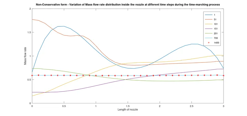
Fig.3: Variation of mass flow rate distribution inside the nozzle at different time steps
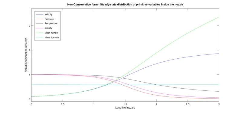
Fig.4:Steady state distribution of primitive varibles inside the nozzle
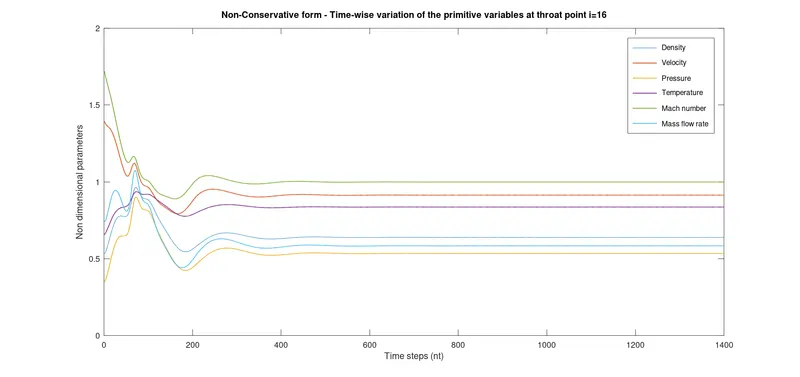
Fig.5: Steady state variation of primitive variables at the throat of the nozzle
(b) Conservative form
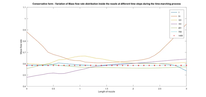
Fig.6: Variation of mass flow rate distribution inside nozzle at different time steps
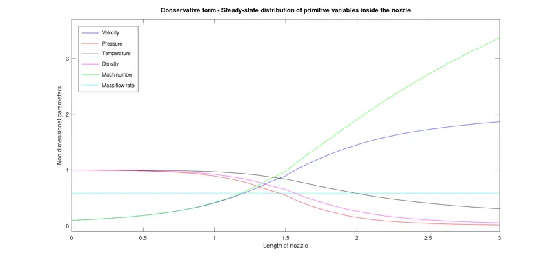
Fig.7: Steady state distribution of primitive variables inside the nozzle
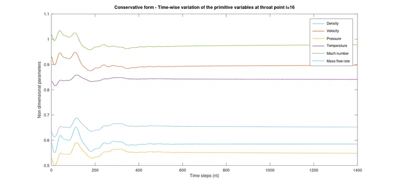
Fig.8: Temporal variation of primitive variable at throat of the nozzle
(c) Conservative Vs Non-Conservative form
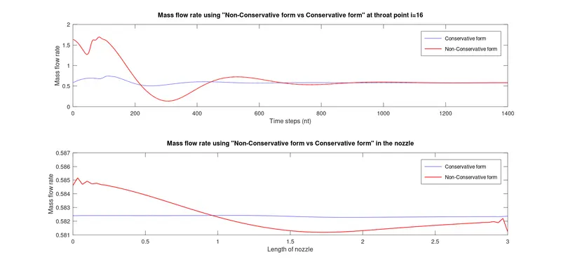
Fig.9: Comparison of mass flow rate for conservative and non conservative form in nozzle and at the throat of the nozzle
(d) Grid Independence study
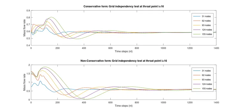
Fig.10: Grid independence test at the throat of the nozzle
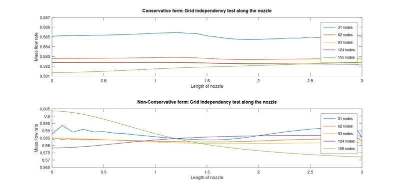
Fig.11: Grid independence test along the nozzle
- Grid independence test has been carried out for the both type of solution methodologies, i.e., conservative and non-conservative. Since the problem is 1 dimensional, only we are concerned with the number of grid points. The grid points has been increased from 31 to 155 and mass flow rate has been used as the variable to determine the grid independence. We could see in both cases as shown in figure 10&11 that, as the grid points are being increased, there is a very slight change in the mass flow rate.But taking the average of the mass flow rate along the length of the nozzle, we can see that, increasing the grid points further beyond 31 does not have a significant effect on the solution, which shows that the solution has became independent of the grid.Thus discretization using 31 grid points is optimum for the given quasi one-dimensional problem.
OBSERVATIONS:
- For the non-conservative case, we can see that, during the initial time step, i.e., as the flow begins through the entry of the nozzle,there is a lot of fluctuations in the solution.But as the time progress, the solution becomes steady.But in contrast for the conservative case, the flow do not suffer much of the oscillation as observed in non-conservative case, this can be seen in figure 3&6.From the figure 9,we are ble to see that the solution reaches a steady state faster for the conservative case and also during the initial stage of the solution, the solution suffers oscillations.
- The plot of the variation of the primitive variables along the length of the nozzle as in figure 4 &7 shows that, at the entry of the nozzle the velocity and mach number of the flow is low, indicating that the flow is subsonic, but this trend continues till the throat region of the nozzle, and there is a gradual increase in the mach number and velocity.But afterwards, the flow enters the supersonic regime and the magnitude of velocity and mach number increases.Subsequently,the density and pressure reduces in this regime.A similar trend is observed in the case of primitive varibles for both conservativve and non conservative form.
- Primitive variables at the throat of the nozzle suffers large oscillations in the solution for non conservative case, but the oscillation is dampened out to an extend for the conservative case. The time taken for the solution to become steady is almost the same in both the cases.
CONCLUSIONS:
After examining the above plots and the results obtained, we can evidently conclude that, the rate of convergence is more in the case of conservative type of the solution and the solution is stable in every part of the domain.Whereas the non-conservative form experiences, oscillations to the solutions during the initial stages, but it dampens out gradually.Yet both the forms are dependable in calculating the solutions which is almost precise.