Week 7 - Minor Project
Aim:-
In this project, the student will have to setup the domain for analysis of flow over an airfoil at subsonic and supersonic regime. The airfoil will be analysed at 3 different angles of attack and the lift and drag coefficient will be compared in all cases Create domain for flow analysis Setup simulation for subsonic and supersonic regimes at 0,5, 10, 15 angle of attack
What is a NACA Airfoil?
NACA stands for National Advisory Committee for Aeronautics, the predecessor to NASA.
NACA developed a series of airfoil shapes for systematic aerodynamic testing. These shapes are widely used in aircraft wings, wind turbines, and flow simulations.Types of NACA Airfoils
The History of Aerofoils
In the early days of flight, pioneers like the Wright brothers used trial and error to design airfoils. However, after 1912, research moved into wind tunnels and laboratories. Key institutions like the University of Göttingen, the Royal Aircraft Factory, and NACA (National Advisory Committee for Aeronautics) advanced the science of aerofoils.
NACA "s Contributions
NACA developed a series of standard airfoil shapes that are still used today. These shapes helped engineers design more efficient aircraft wings and engines. NACA also introduced innovations like the NACA duct for better airflow.
Beyond Air :Hydrofoils
The same principles of aerofoils are used in hydrofoils—aerofoil-like shapes used in water to lift boats above the surface and reduce drag.
Conclusion
Aerofoils are essential for efficient flight and are used in everything from aircraft wings to wind turbines. Over time, through research and testing, they have become an integral part of engineering, helping us achieve better performance with less energy.
An airfoil is a streamlined shape designed to generate aerodynamic lift when air flows over it. It is the fundamental shape used in wings, turbine blades, and propellers.
The NACA 0012 is a symmetrical airfoil from the NACA 4-digit series developed by the National Advisory Committee for Aeronautics (NACA), the predecessor of NASA
First digit (0) → Maximum camber = 0% (symmetric)
Second digit (0) → Location of maximum camber = 0% (none)
Last two digits (12) → Maximum thickness = 12% of chord length
This means:
The airfoil is perfectly symmetric about the chord line.
It has no camber, so at 0° angle of attack, it produces zero lift.
Maximum thickness occurs at 30% chord (standard for 4-digit series).
Geometry Preparation
Import the airfoil coordinates (from UIUC Airfoil Database or use tools like
XFOIL).Ensure clean, closed geometry
Add a farfield boundary (e.g., circular or rectangular domain around the airfoil, ~20x chord length).
AirFoil Nomenclature
Chord
The chord is the straight-line distance between the leading edge (front) and the trailing edge (rear) of the airfoil.
Leading EDge
The leading edge is the front point of the airfoil, where the curvature is at its maximum.
Trailing Edge
The trailing edge is the rear point of the airfoil, where the maximum curvature occurs as the airflow exits.
Chord Line
The chord line is an imaginary straight line connecting the leading edge to the trailing edge
Upper Surface (Suction Surface)
The upper surface (or suction surface) is the top part of the airfoil, where airspeed is higher and static pressure is lower.
Lower Surface (Pressure Surface)
The lower surface (or pressure surface) is the bottom part of the airfoil, where airspeed is slower and static pressure is higher.
Angle of Attack (AOA)
The angle of attack (AOA) is the angle between the chord line and the direction of the incoming airflow
Lower Surface (Pressre Surface
An airfoil is defined by several key features, each contributing to its aerodynamic performance:
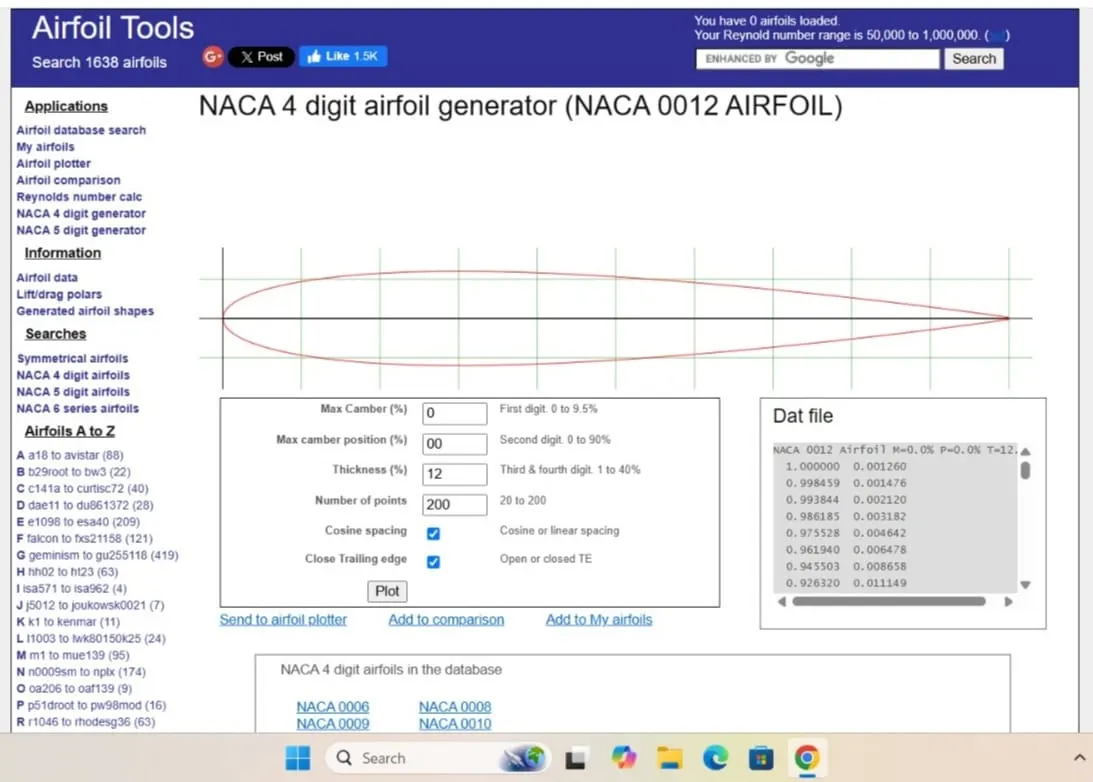
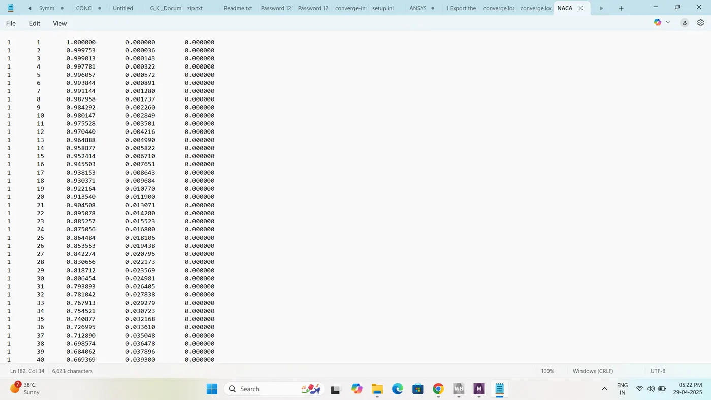
some perpetration in word pad:-
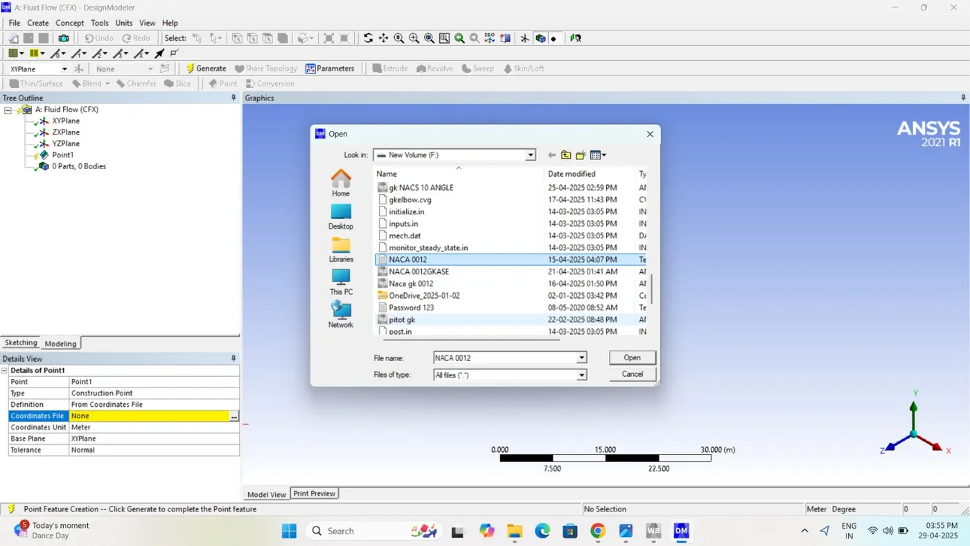
Input of the aerofoiled coronet file in Design Modeler:-
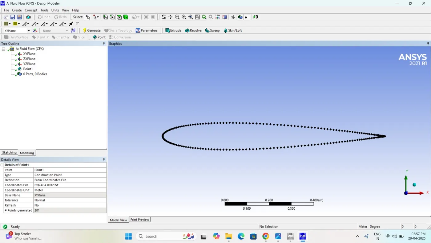
 I'm choosing the Point opisthion
To connecting the point taking 3D Curves option
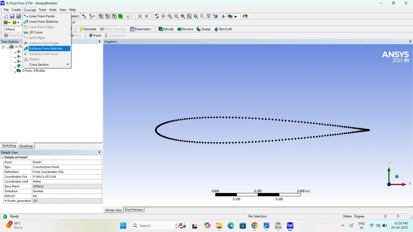
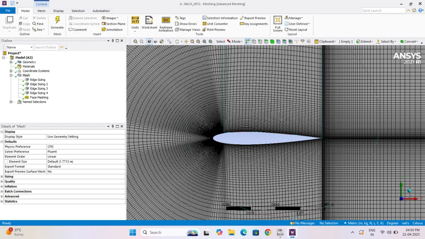
Mesh Types
| Region | Mesh Type | Description |
|---|---|---|
| Near airfoil wall | Structured/Refined | Use boundary layer mesh with inflation layers |
| Wake region (trailing edge) | Refined | To capture vortex shedding and separation |
| Farfield | Coarser mesh | Less gradient, larger cells are okay |
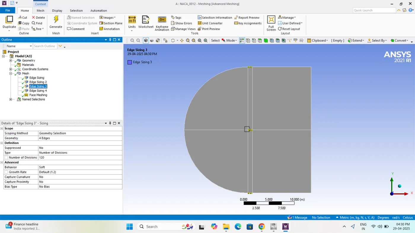
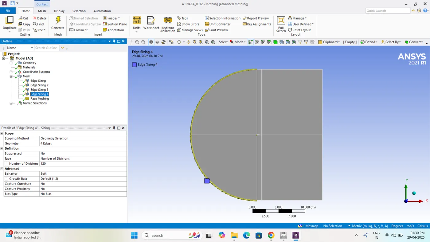
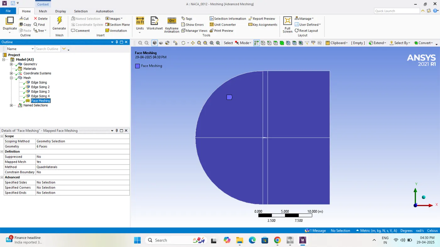
To preparing the mesh taking mesh in side sizing option to different location generating sizing
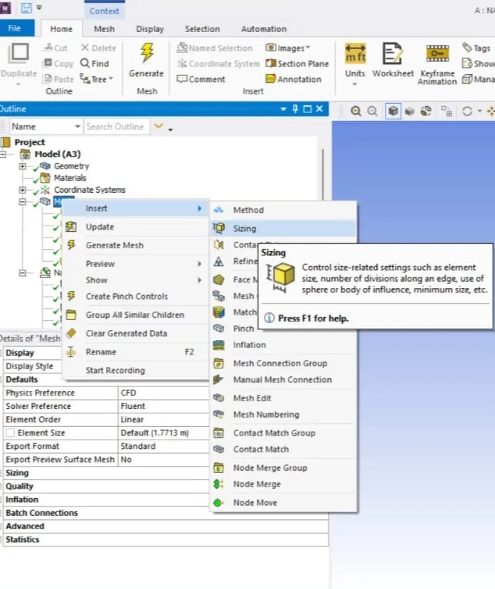
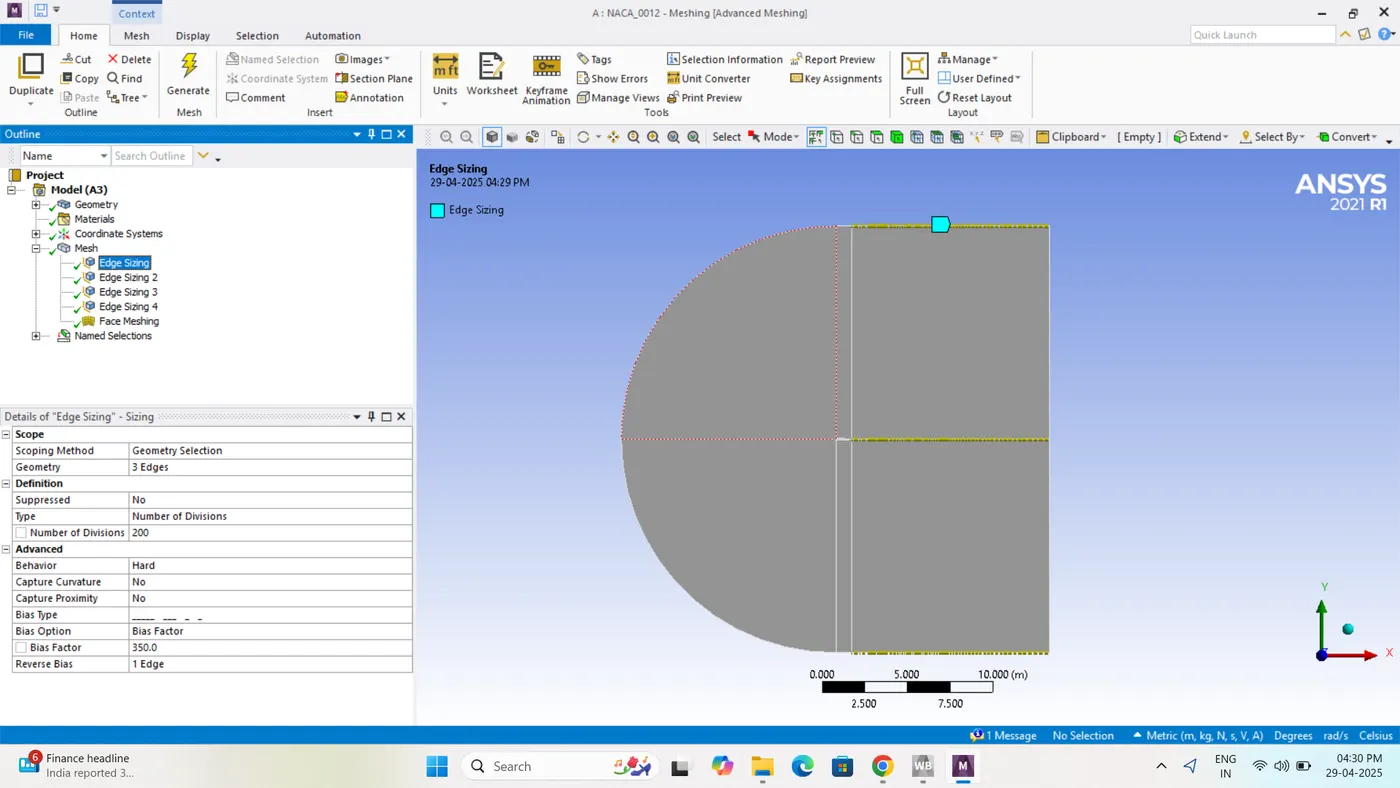
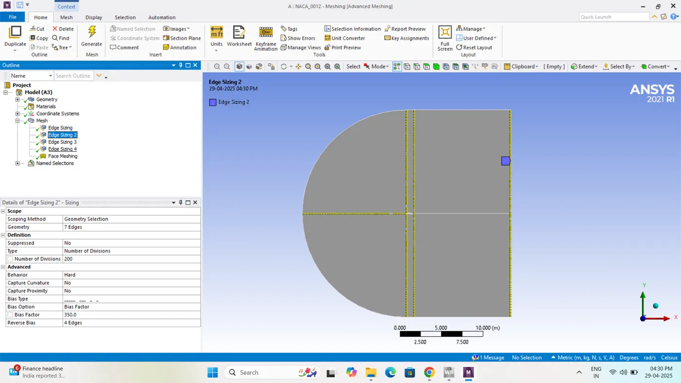
. Meshing Tips
Use structured mesh ( C-grid) for best accuracy around the airfoil.
Use unstructured mesh if automation is needed but ensure smooth transitions.
Refinement zones in:
Leading edge
Trailing edge
Airfoil surface
Wake region
Domain and Mesh Setup (Explain Process Step-by-Step)
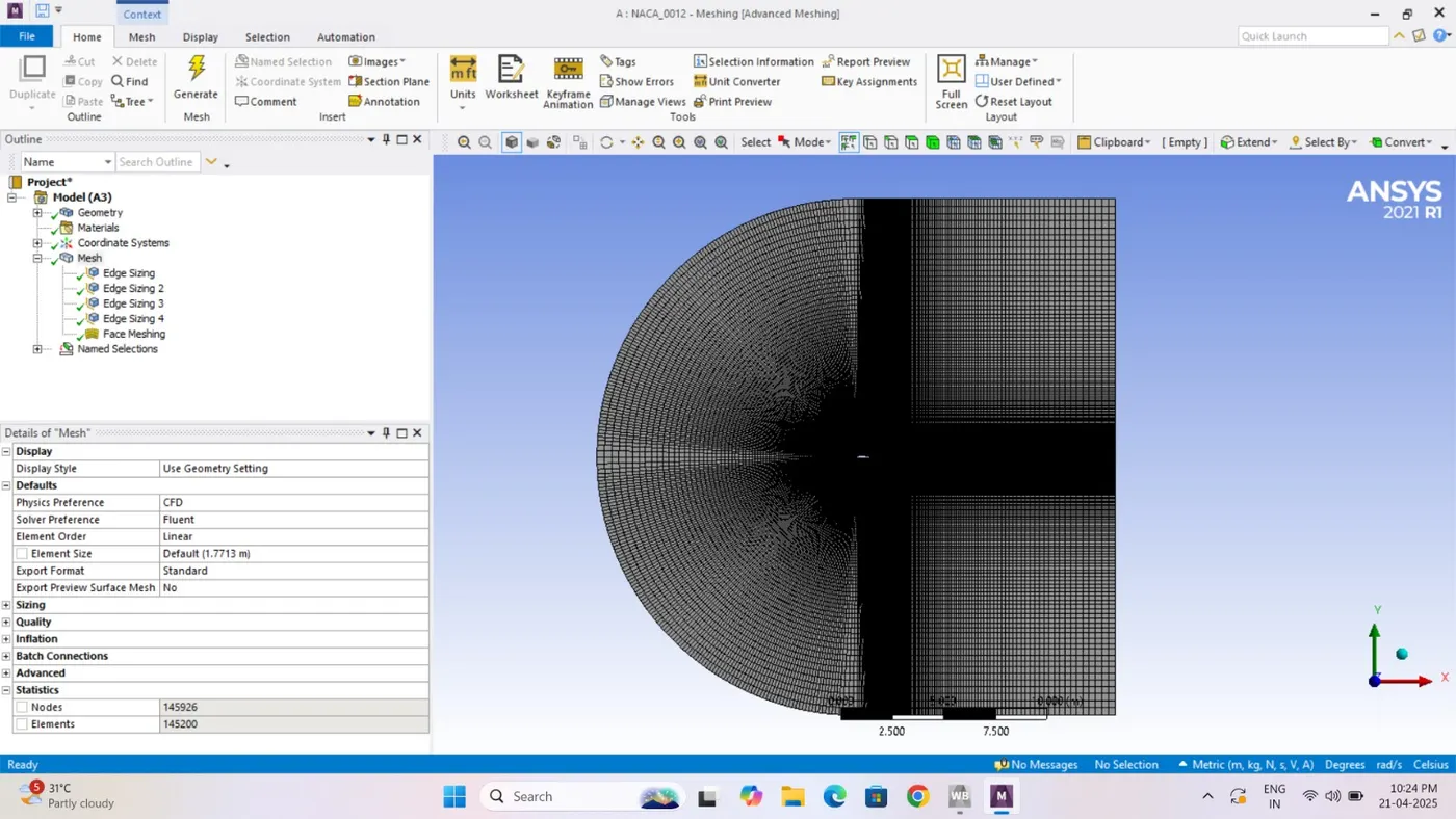
“I created a C-type domain with sufficient space around the airfoil to avoid boundary effects — about 20 times the chord vertically and 10 times downstream. I used structured meshing with finer elements near the airfoil surface to capture the boundary layer accurately. I calculated the first layer thickness based on the desired y+ value for turbulence modeling.”
.
The airfoil will be analysed at 3 different angles of attack and the lift and drag coefficient will be compared in all cases Create domain for flow analysis Setup simulation for subsonic and supersonic regimes at 0,5, 10, 15 angle of attack
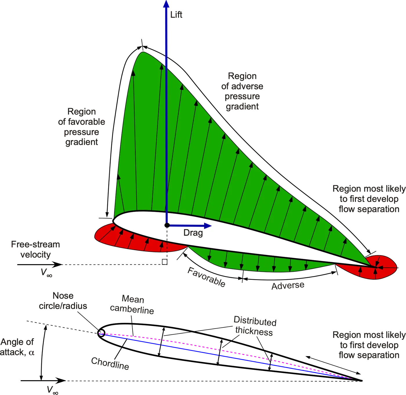
It shows a cambered airfoil (curved shape) with:
-
Flow direction from left to right (
V∞= free-stream velocity). -
Pressure distribution on the top (upper surface) and bottom (lower surface).
-
Lift and drag acting on the airfoil.
-
Regions where flow separation can occur.
Pressure Gradient Regions
Favorable Pressure Gradient:
-
What it is: Pressure decreases as air moves along the surface.
-
Where: Front part (leading edge) of the airfoil.
-
Effect: Helps air stick to the surface (attached flow).
Adverse Pressure Gradient:
-
What it is: Pressure increases as air flows toward the trailing edge.
-
Where: Back part (trailing edge) of the airfoil.
-
Effect: Slows down the airflow, may cause flow separation.
💡 Flow separation usually starts in this adverse pressure gradient region.
Forces on the Airfoil
-
Lift (↑): Acts perpendicular to the free-stream flow. Caused by lower pressure on top and higher pressure on the bottom.
-
Drag (→): Acts parallel to the free-stream. Caused by resistance and separation of flow.
Airfoil Geometry (Bottom Figure)
-
Chord line: Straight line from leading to trailing edge.
-
Camber line: Midline between top and bottom surfaces – shows curvature.
-
Angle of attack (α): Angle between the chord and the free-stream.
-
A higher angle of attack increases lift up to a point, but too much will cause stall.
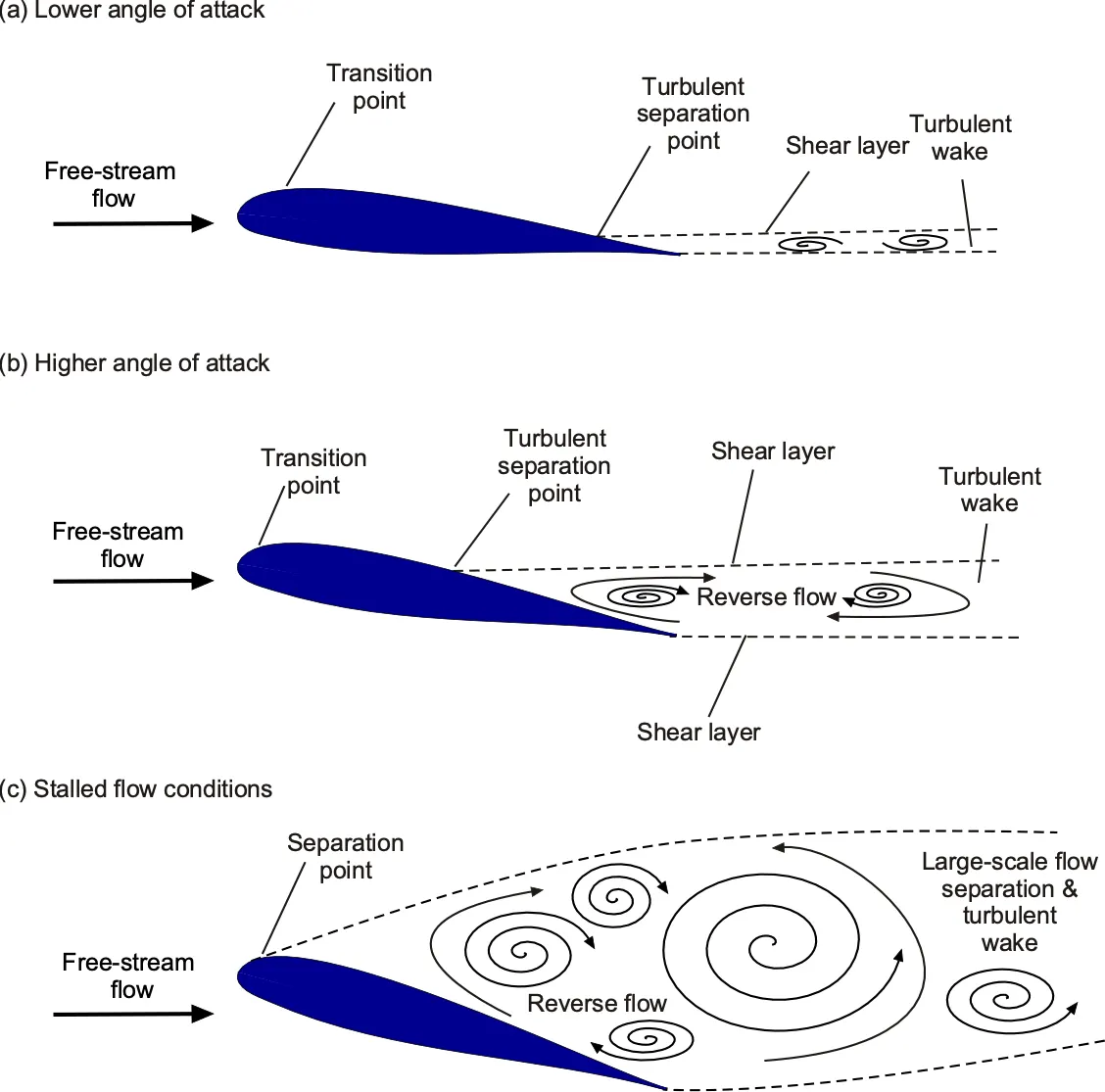
(a) Lower angle of attack
-
Flow condition: Attached flow.
-
Transition point: Laminar flow transitions to turbulent flow smoothly.
-
Turbulent separation point: Flow separates only slightly near the trailing edge.
-
Wake: Small, with weak vortices.
-
Effect: Efficient lift generation with minimal drag.
(b) Higher angle of attack
-
Flow condition: Partial flow separation.
-
Transition point: Moves slightly forward.
-
Turbulent separation point: Moves forward compared to (a).
-
Reverse flow: Begins in the separated region, causing a shear layer.
-
Wake: More turbulent and larger than in (a).
-
Effect: Lift starts to reduce, drag increases. The airfoil is near stall.
(c) Stalled flow conditions
-
Flow condition: Fully separated flow.
-
Separation point: Very forward on the airfoil.
-
Reverse flow: Dominant, with multiple vortices forming.
-
Large-scale separation and turbulent wake: Encompasses a significant portion of the upper surface and wake.
-
Effect: Lift drops significantly, drag is high. The airfoil is in stall.
Summary Table:
| Condition | Transition Point | Separation Point | Reverse Flow | Wake Characteristics | Lift | Drag |
|---|---|---|---|---|---|---|
| (a) Lower AoA | Near mid-chord | Near trailing edge | Minimal | Small, weak vortices | High | Low |
| (b) Higher AoA | Forward | Mid-chord | Noticeable | Larger, turbulent | Reducing | Increasing |
| (c) Stalled | Very forward | Early | Dominant | Large, chaotic | Very low | Very high |
What is Lift?
Lift is the aerodynamic force that pushes the airfoil upward, perpendicular to the direction of the airflow. Without lift, an airplane cannot fl.
Lift (L)
Definition: Lift is the upward force that acts perpendicular to the direction of airflow. It allows aircraft to rise off the ground.
-
Why It Happens:
Due to the Bernoulli’s principle and Newton’s third law:-
Air moves faster over the upper surface (convex) of the airfoil.
-
Faster air = lower pressure on top.
-
Slower air = higher pressure below.
-
This pressure difference generates lift.
-
-
Lift Formula:
L=CL⋅21ρV2AWhere:
-
L = Lift force (N)
-
CL = Lift coefficient (depends on AoA and shape)
-
ρ = Air density (kg/m³)
-
V = Free-stream velocity (m/s)
-
A = Reference area (typically the wing area)
-
-
Observation:
-
As angle of attack increases, CL increases until stall occurs.
-
Symmetric airfoils like NACA 0012 generate no lift at 0° AoA, but generate lift at non-zero AoA.
What is Drag?
Drag is the resistive force that acts parallel and opposite to the direction of airflow. Drag slows down the airfoil.Definition: Drag is the resisting force that acts parallel and opposite to the direction of airflow. It slows down the object moving through air.
Drag (D)
-
Types of Drag:
-
Pressure Drag (form drag): Caused by pressure difference in front and back of the airfoil.
-
Skin Friction Drag: Due to friction between air and the airfoil’s surface (boundary layer).
-
-
Drag Formula:
D=CD⋅21ρV2AWhere:
-
D = Drag force (N)
-
CD = Drag coefficient (depends on shape, flow speed, surface roughness)
-
ρ,V,A same as above.
-
-
Observation:
-
Drag increases with velocity and AoA.
-
At high AoA, flow separation increases drag significantly.
-
At supersonic speeds, wave drag (due to shockwaves) is added.
-
olver Setup Summary: NACA 0012 Airfoil CFD Simulation
Solver Type
-
Incompressible Flow (Subsonic: 52.15 m/s):
-
Pressure-based solver
-
Suitable for low-speed flows where density changes are negligible.
-
-
-
Compressible Flow (Supersonic: 273 m/s):
-
Density-based solver
-
Required for high-speed flows (typically above Mach 0.3) where compressibility effects and shock waves become significant.
-
-
Turbulence Model
-
Spalart–Allmaras Model (1-equation)
-
Specially developed for aerodynamic applications like airfoils.
-
Performs well in attached boundary layers and moderate separations.
-
Computationally efficient and accurate for external flows.
-
Energy Equation
-
ON: for Compressible flow
-
Because temperature changes and shock heating are important.
-
-
OFF: for Incompressible flow
-
Temperature does not significantly affect the density or flow field.
-
Numerical Methods
-
Coupled Solver Scheme
-
Solves momentum and continuity equations together.
-
Provides fast convergence for steady-state flows.
-
Well-suited for high-speed external flows.
-
-
Pseudo-transient: OFF
-
Since you're solving steady-state problems, time stepping is not needed.
-
Iterations
-
1000to 5000 iterations
-
Number depends on residual convergence and stability of the solution.
-
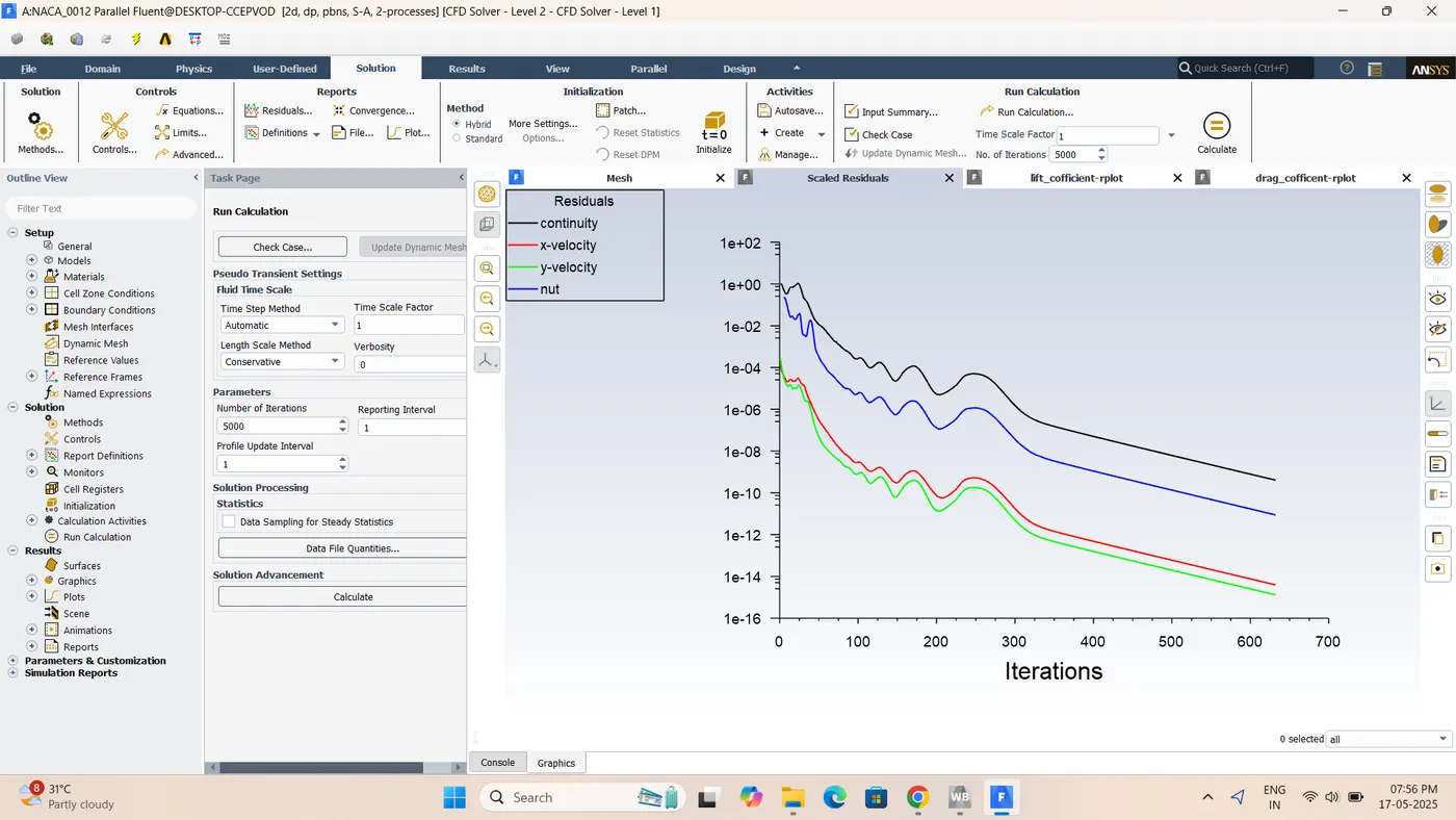
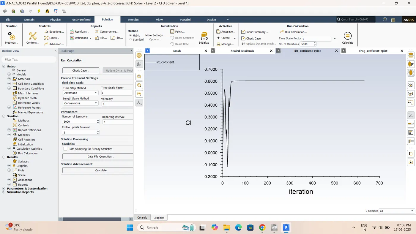
Monitor lift/drag coefficients and residuals to confirm convergence.
-
Initialization
-
Hybrid Initialization
-
Combines features of standard and physical-based initialization.
-
Suitable for both structured and unstructured meshes.
-
Recommended for complex domains like external flows around airfoils.
-
Boundary Conditions
Compressible Case
-
Inlet :velociry Inlet
-
Velocity = 374.33 m/s
-
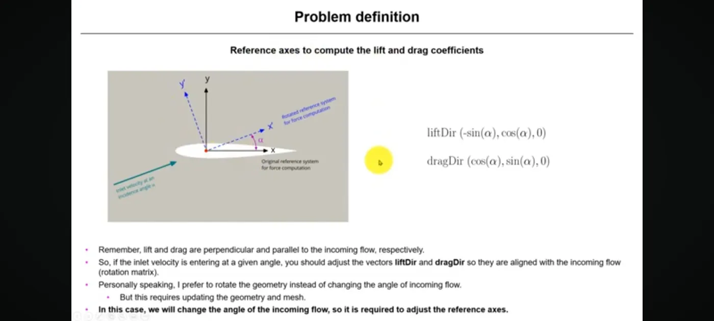
Set flow direction vector for different angles of attack.
-
-
Airfoil Surface:Wall (No-Slip)
-
Air velocity = 0 at the surface due to no-slip condition.
-
-
Outlet: Pressure Outlet
-
Gauge Pressure = 0 Pa (atmospheric)
-
Incompressible Case
-
Inlet: Velocity Inlet
-
Velocity = 52.15 m/s
-
Adjust direction for each AoA (e.g., using components of velocity vector)
-
-
Airfoil: No-slip wall
-
Outlet: pressure Outlet
-
ssureGauge Pressure = 0 Pa
-
Additional Tip:
To set angle of attack (AoA):
-
Change the direction vector of inlet velocity:
Vx=V⋅cos(α),Vy=V⋅sin(α)For example, at AoA = 10°:
-
Vx=V⋅cos(10∘)
-
Vy=V⋅sin(10∘)
-
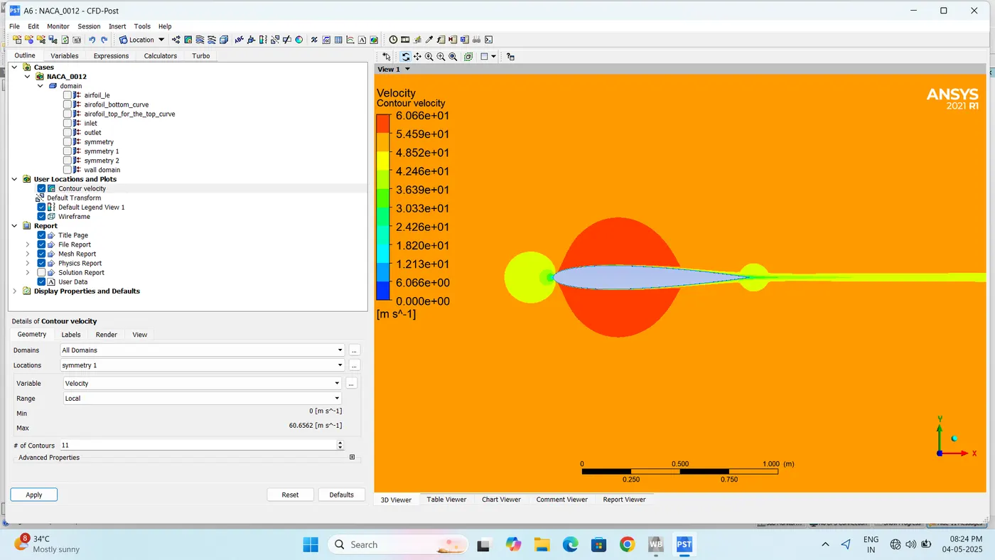
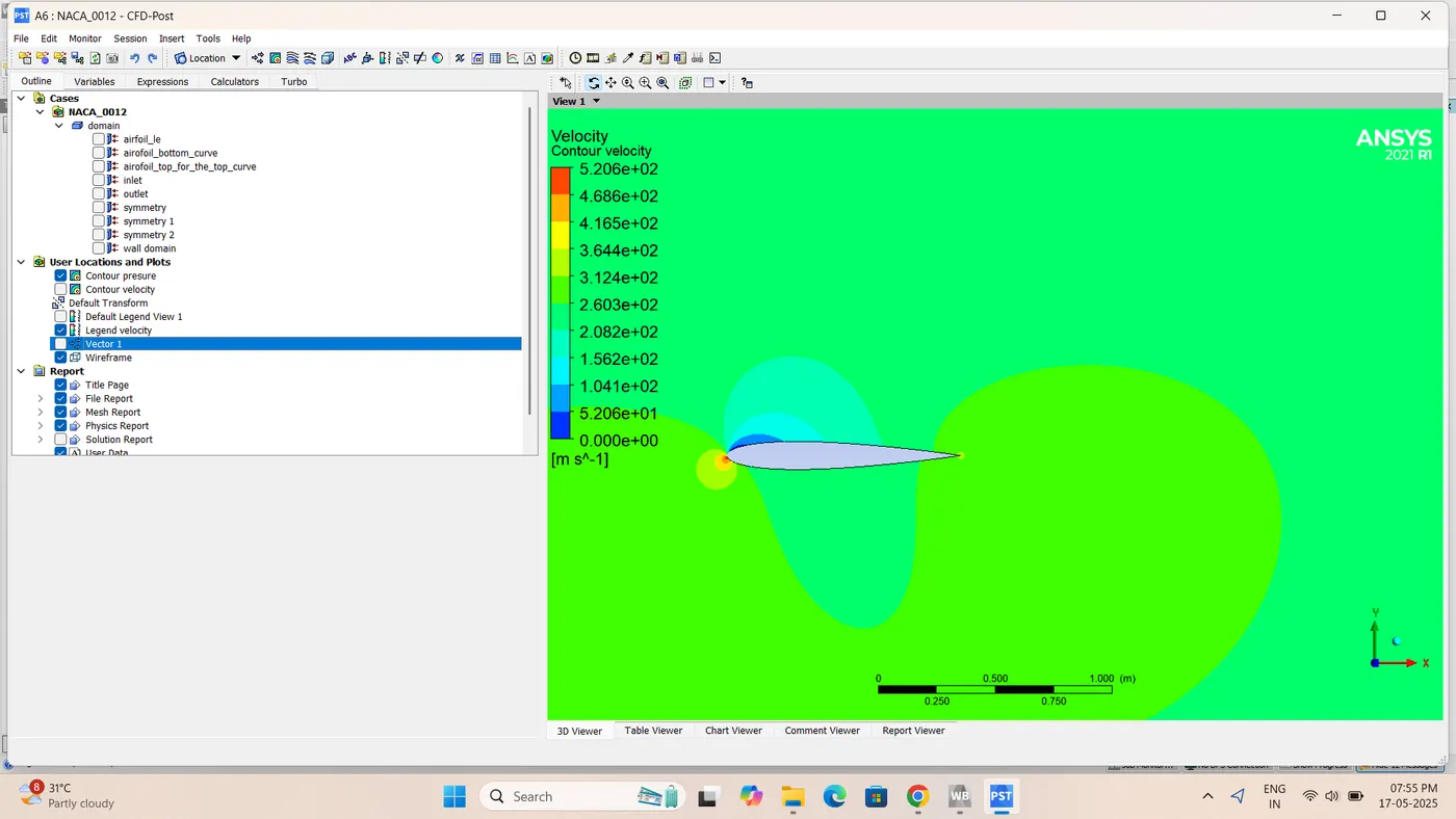
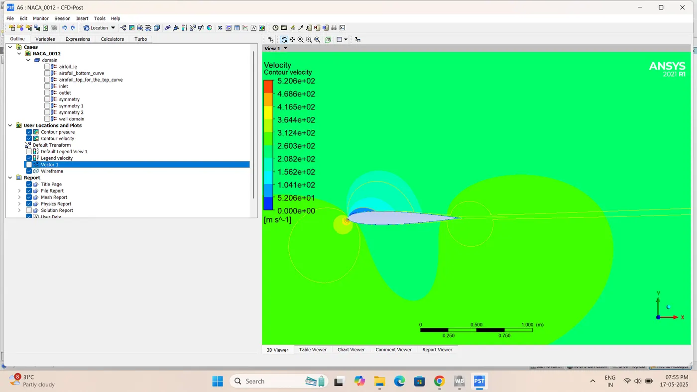
:-Incompressible 0 angle of attack(V =52m/s)Velocity Contour
:-Velocity contour
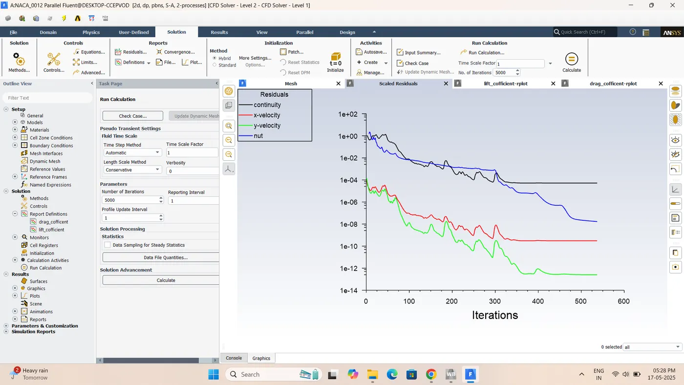
:-Pressure Contour

:-itreations
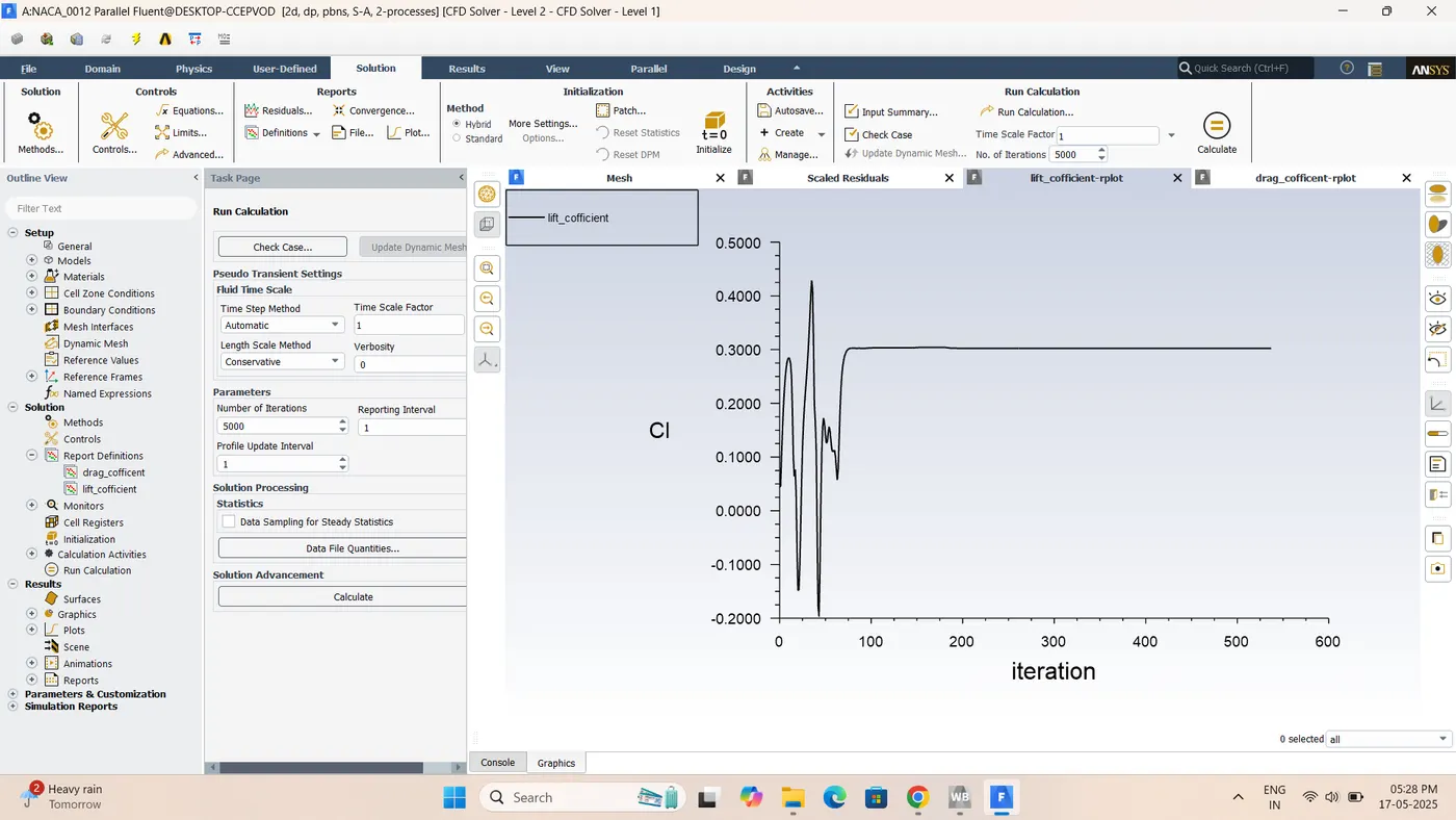
:-Cl Lift
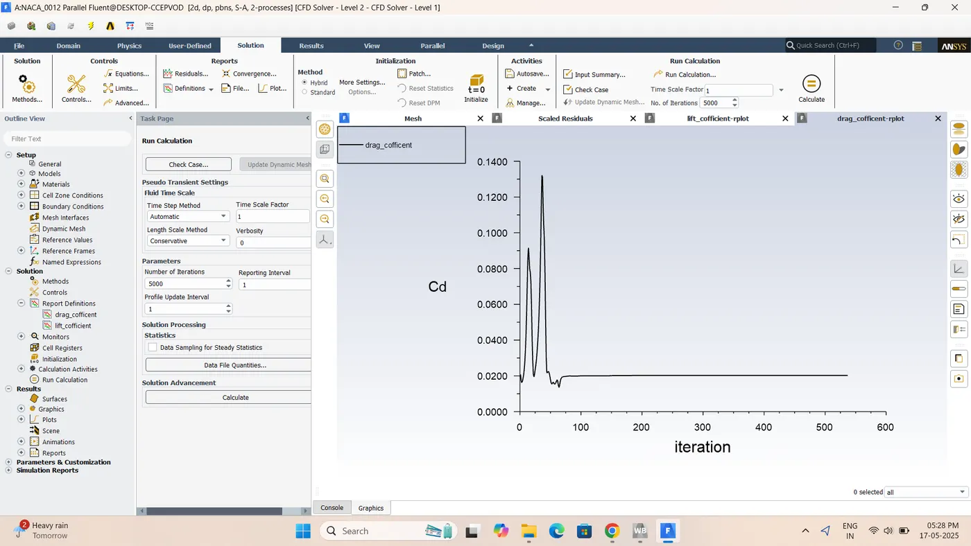
:-Cd Drag
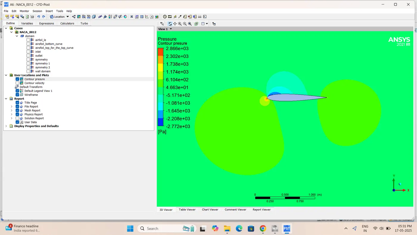
:-Incompressible 5 angle of attack(V =52m/s)Velocity Contour
:-Pressure contour
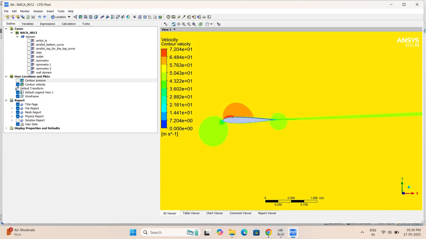
:-velocity contour
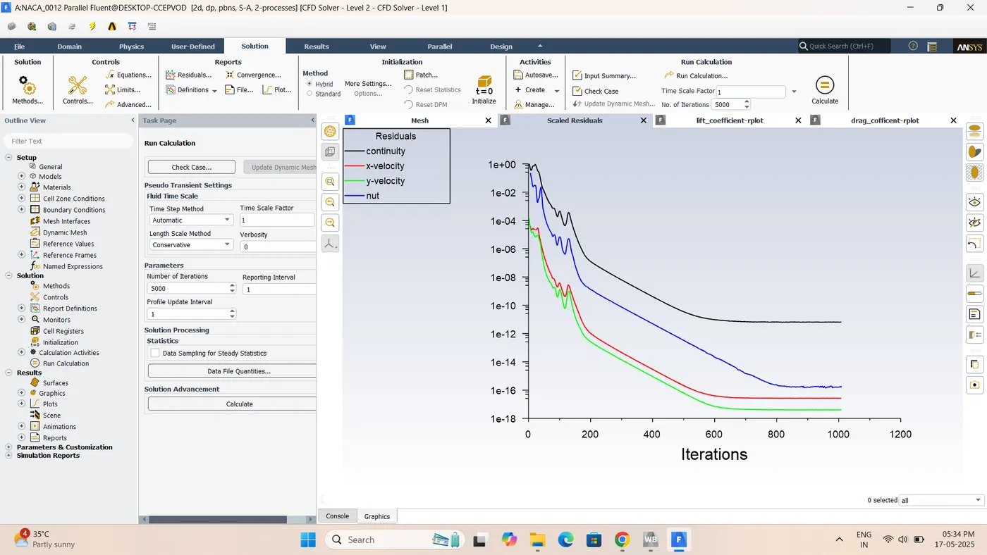
:-iterations
:-Cl lift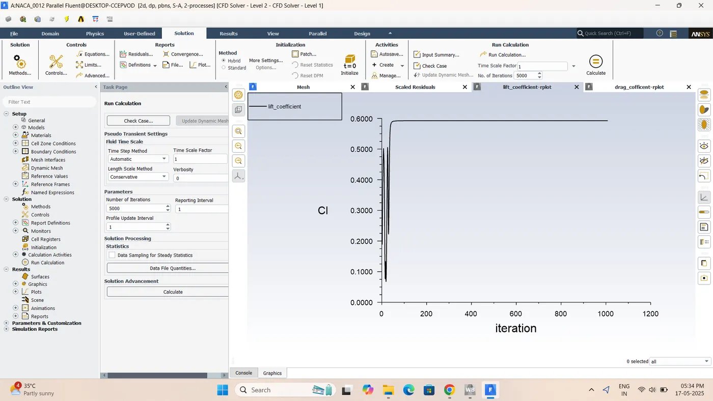
:-Cd Drag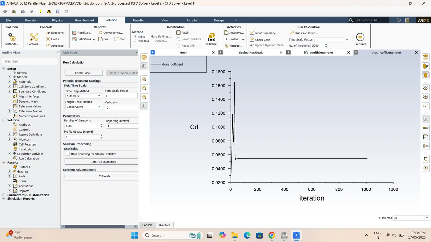
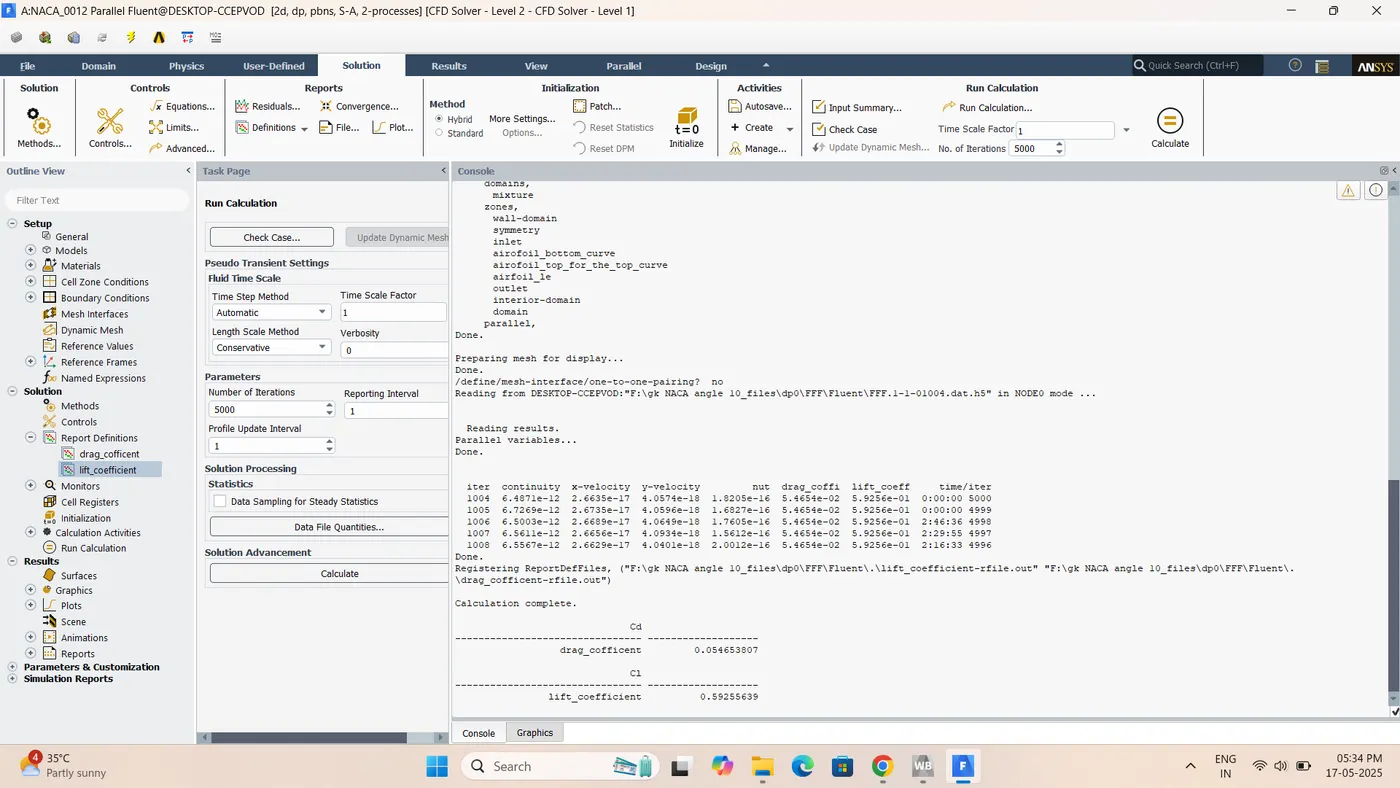
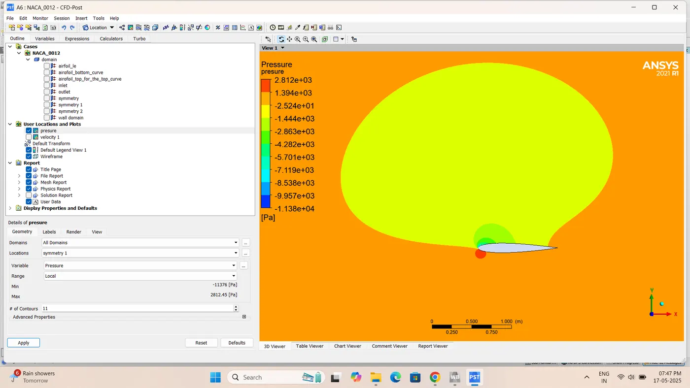
:-Incompressible 10 angle of attack(V =52m/s)Velocity Contour
:-Pressure contour
:-Velocity contour
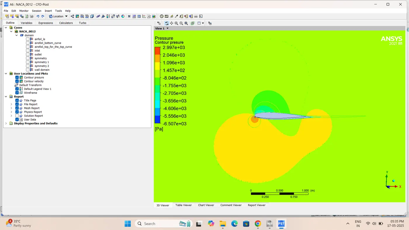
:-Iterations
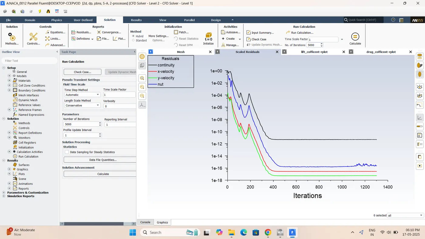
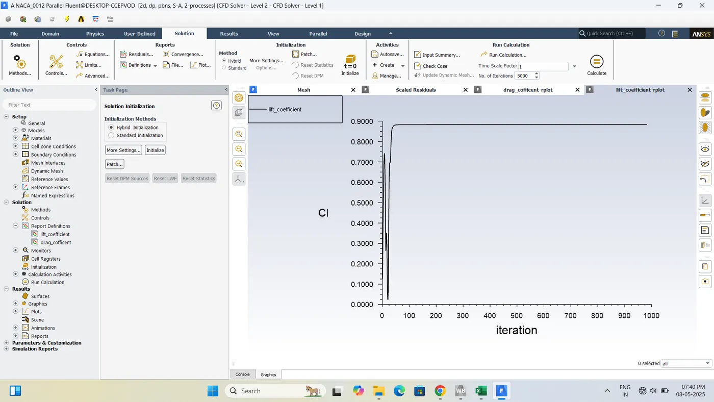
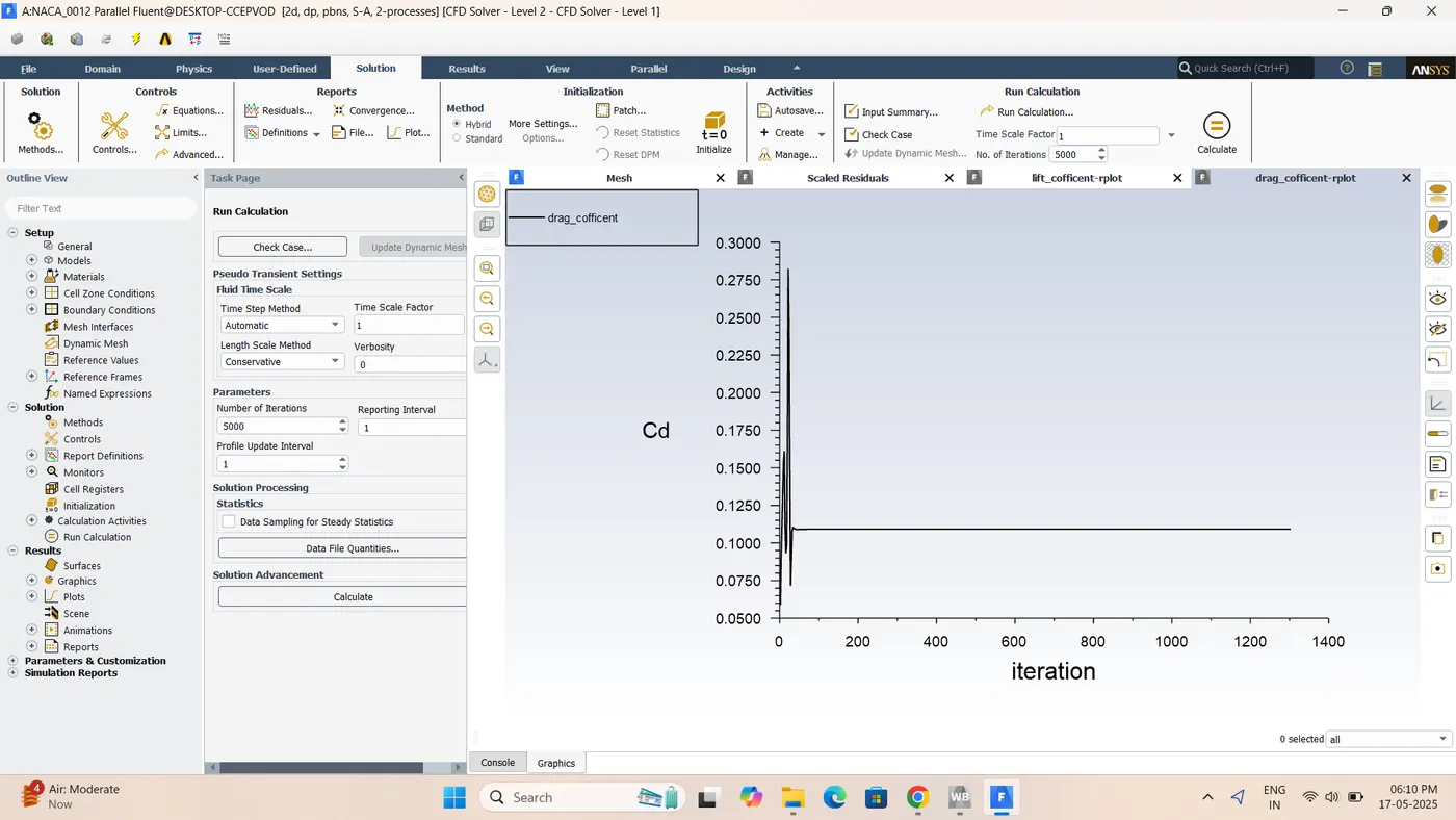
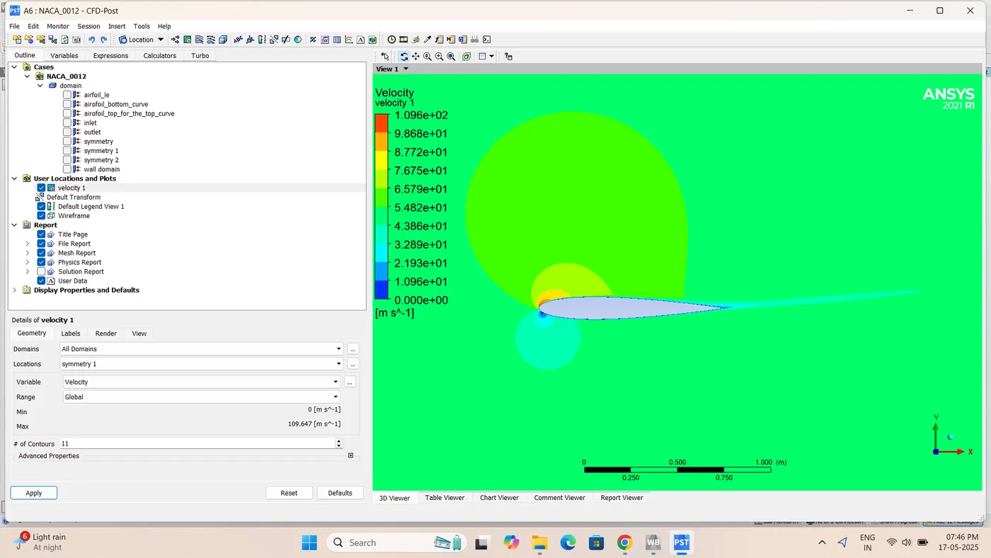
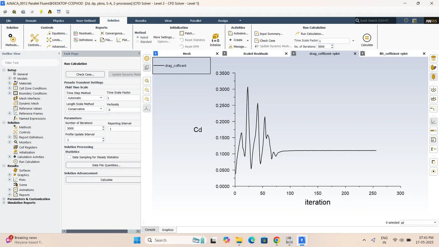
:-Incompressible 15 angle of attack(V =52m/s)Velocity Contour
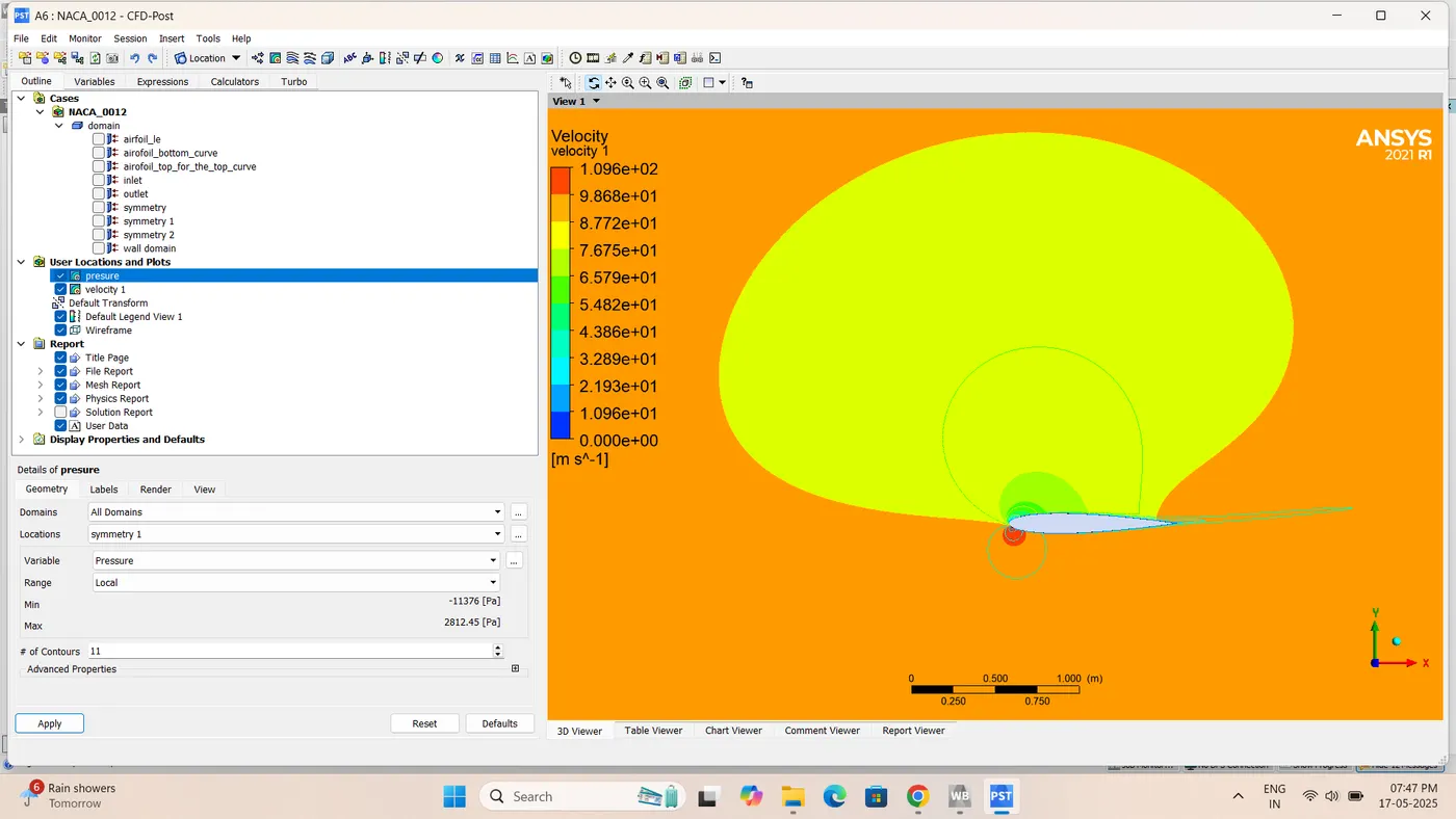
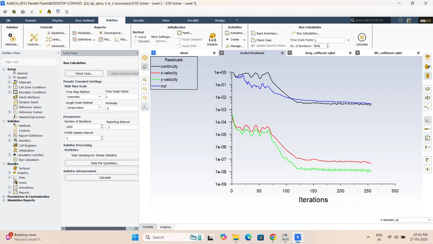
:-Cd Drag
:-Cl Lift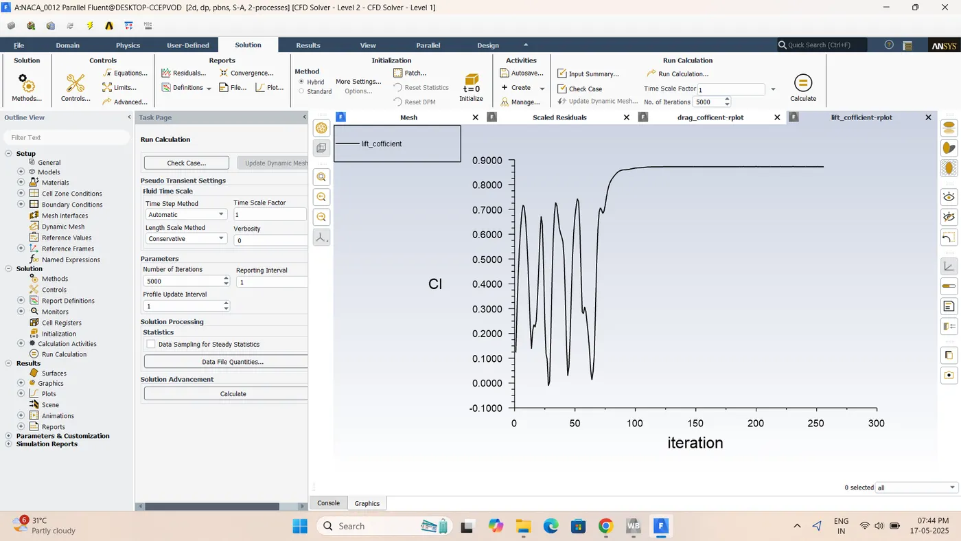
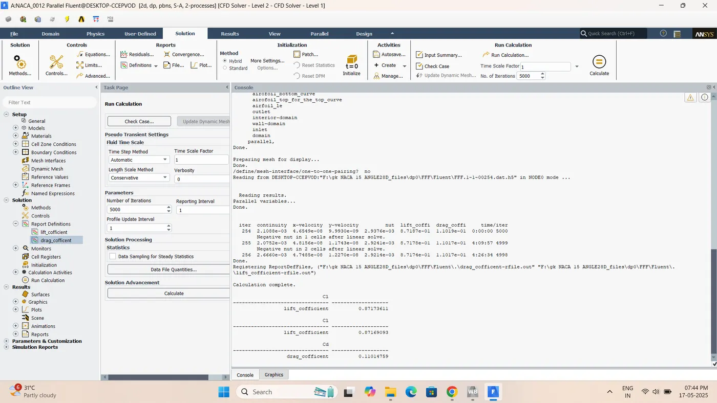
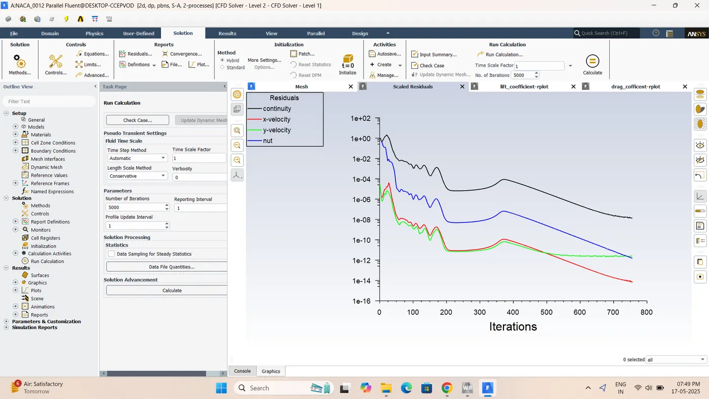
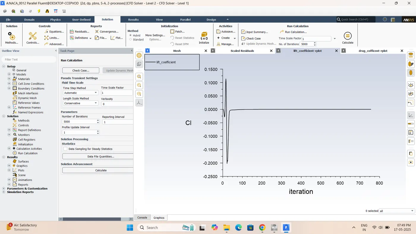
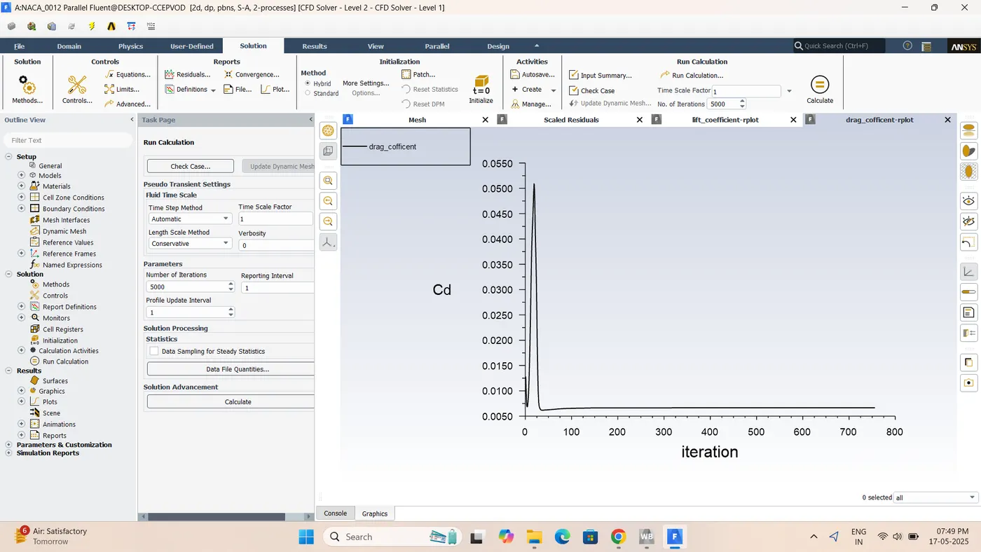
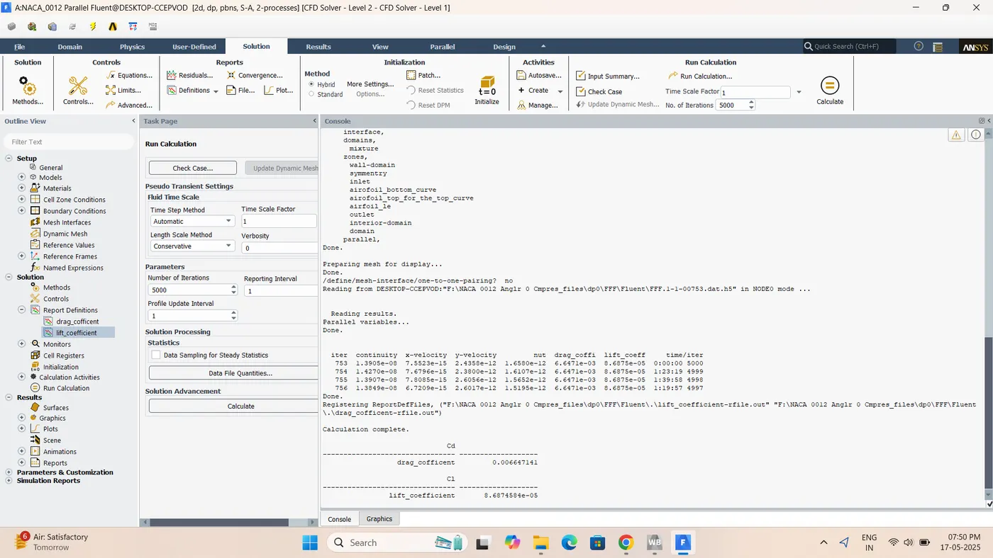
:-compressible 0 angle of attack(V =374.33m/s)Velocity Contour
:-Pressure contour
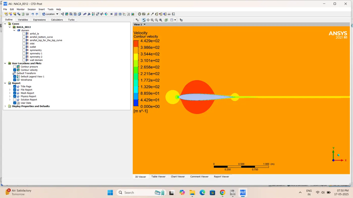
:-Velocity contour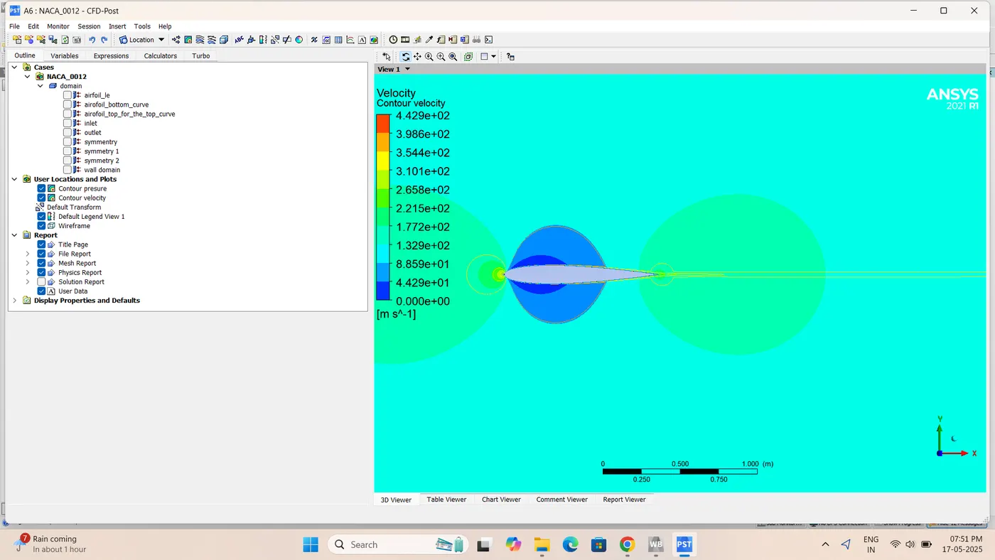
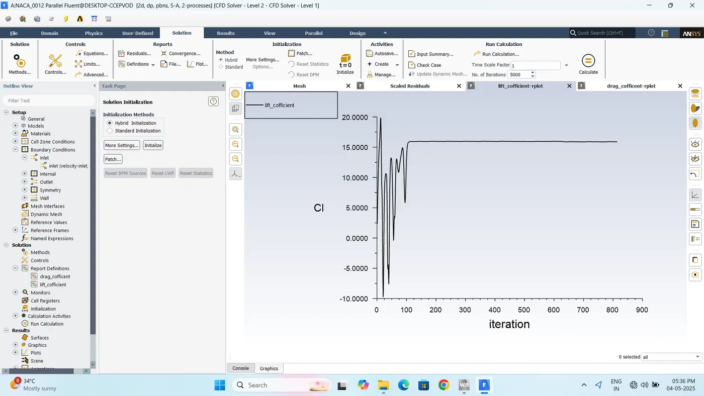
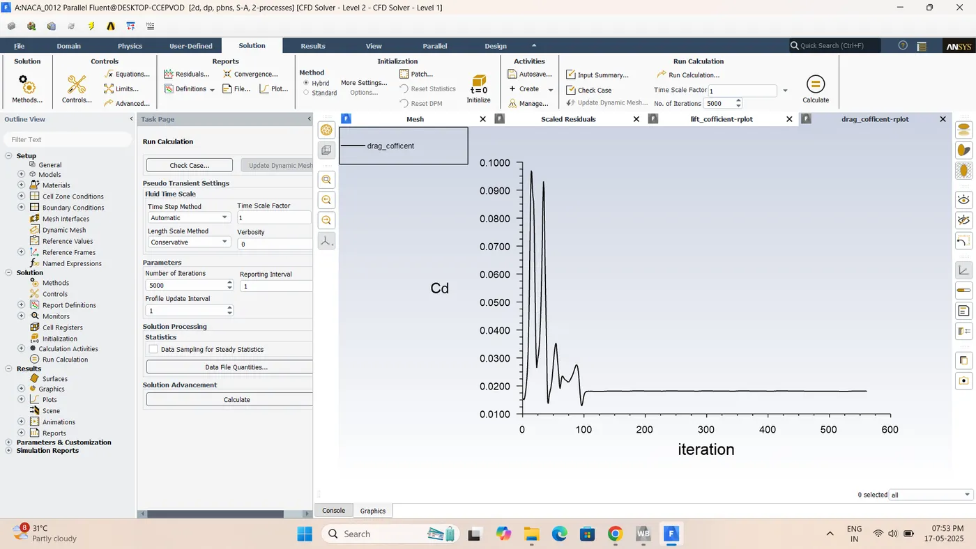
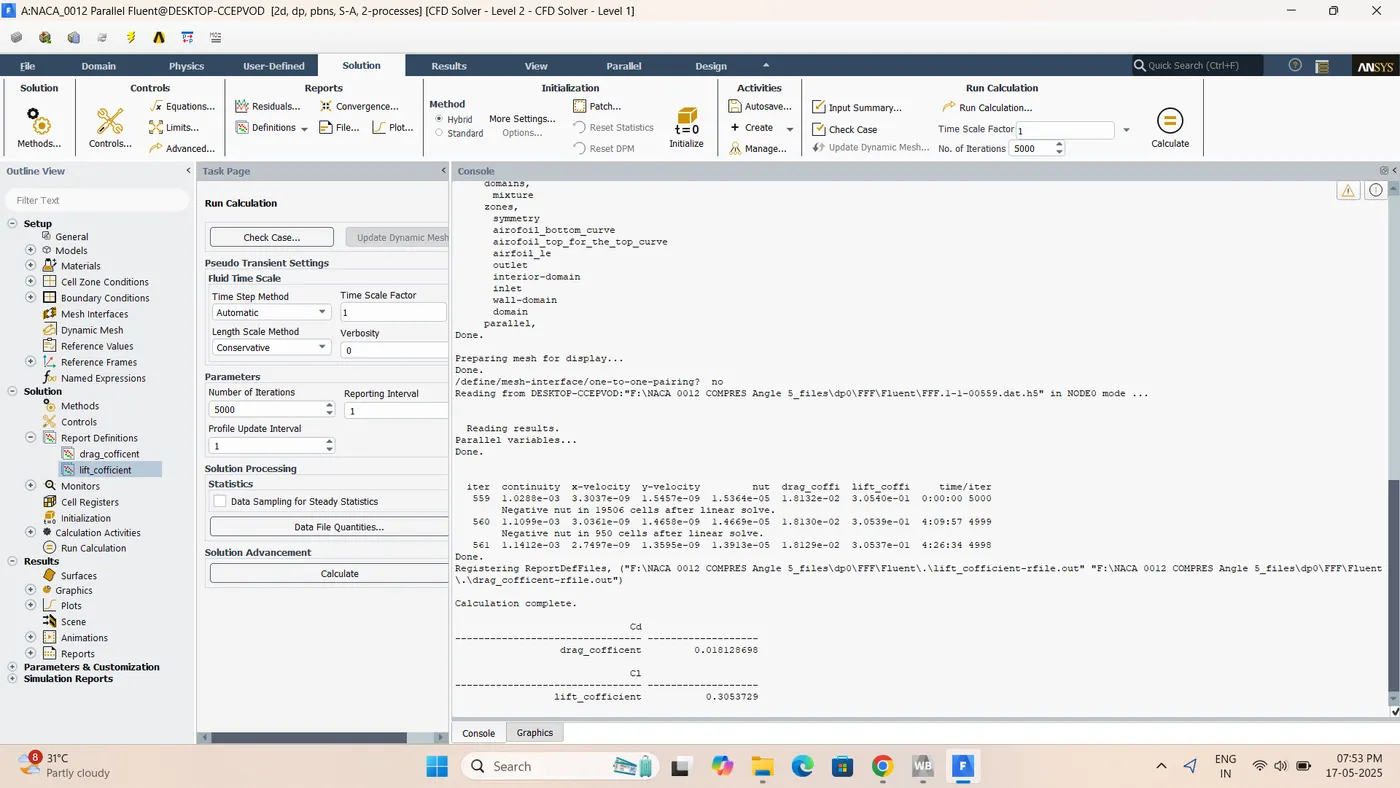
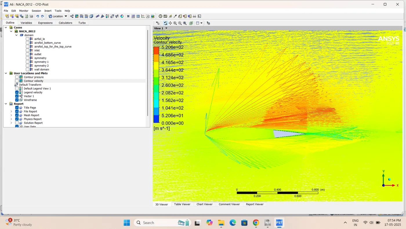
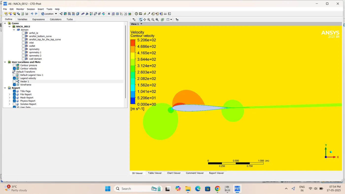
:-compressible 5 angle of attack(V =374.33m/s)Velocity Contour
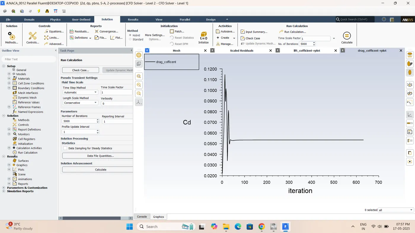
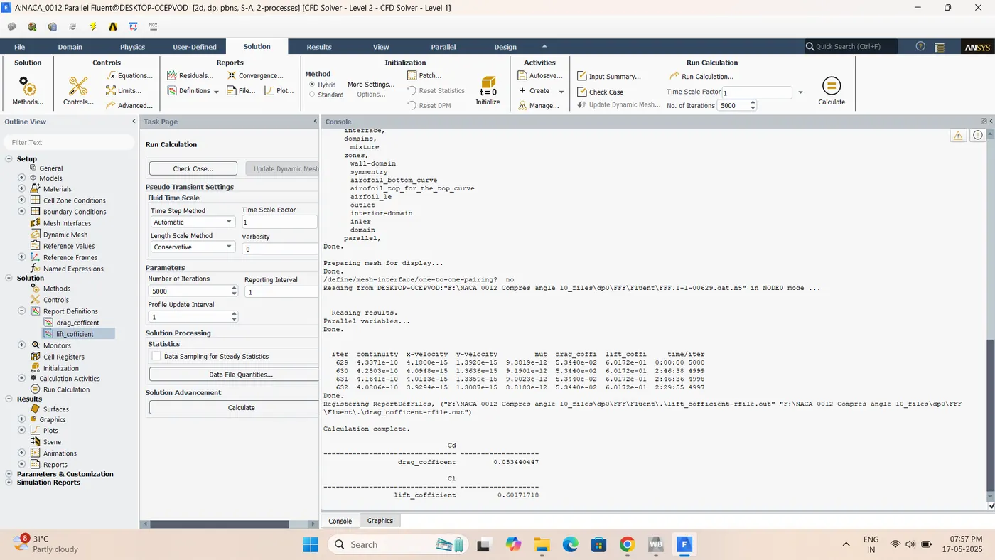
:-compressible 10angle of attack(V =374.33m/s)Velocity Contour
:-OPressur Contour
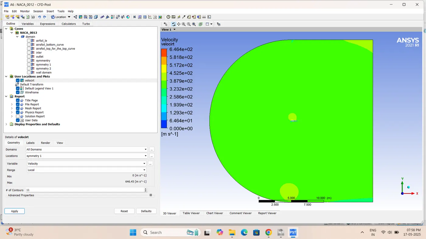
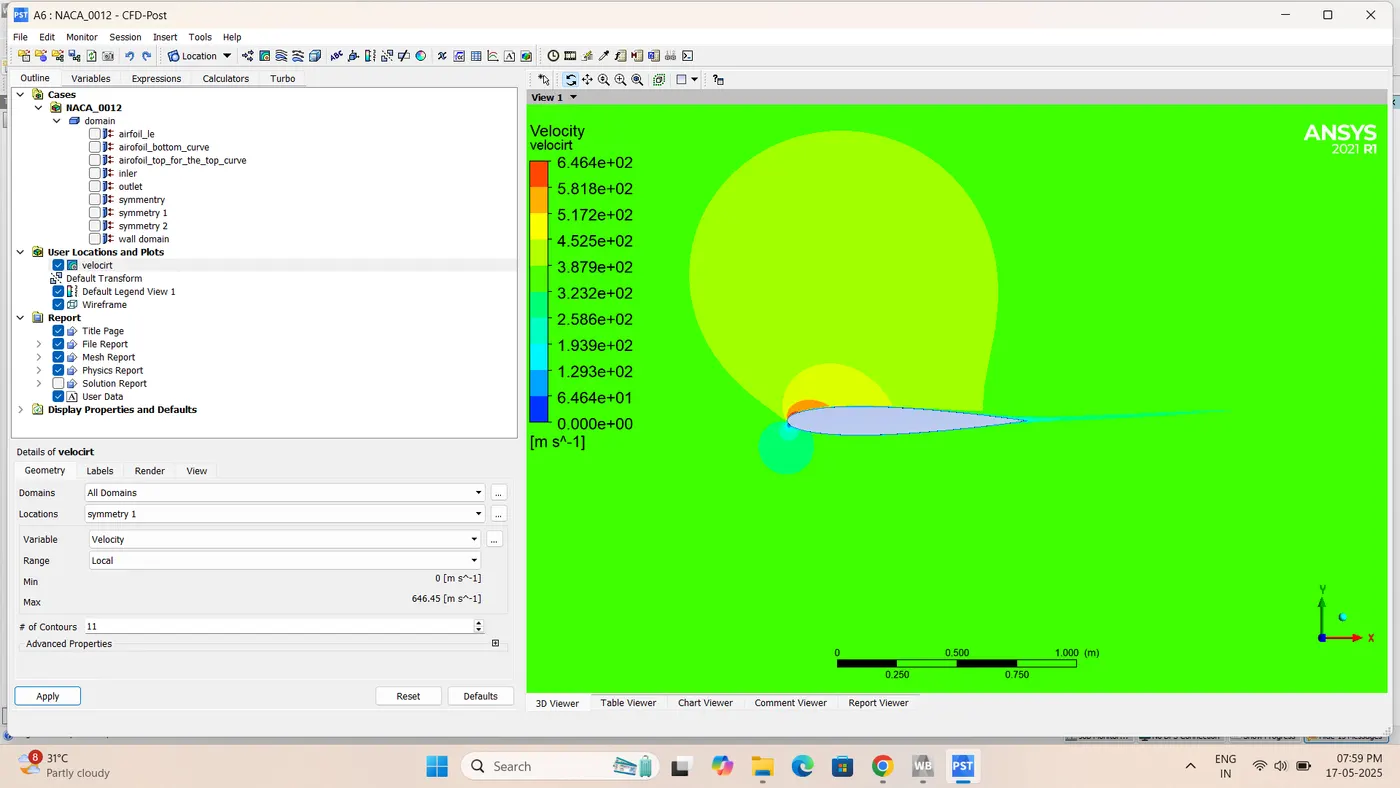
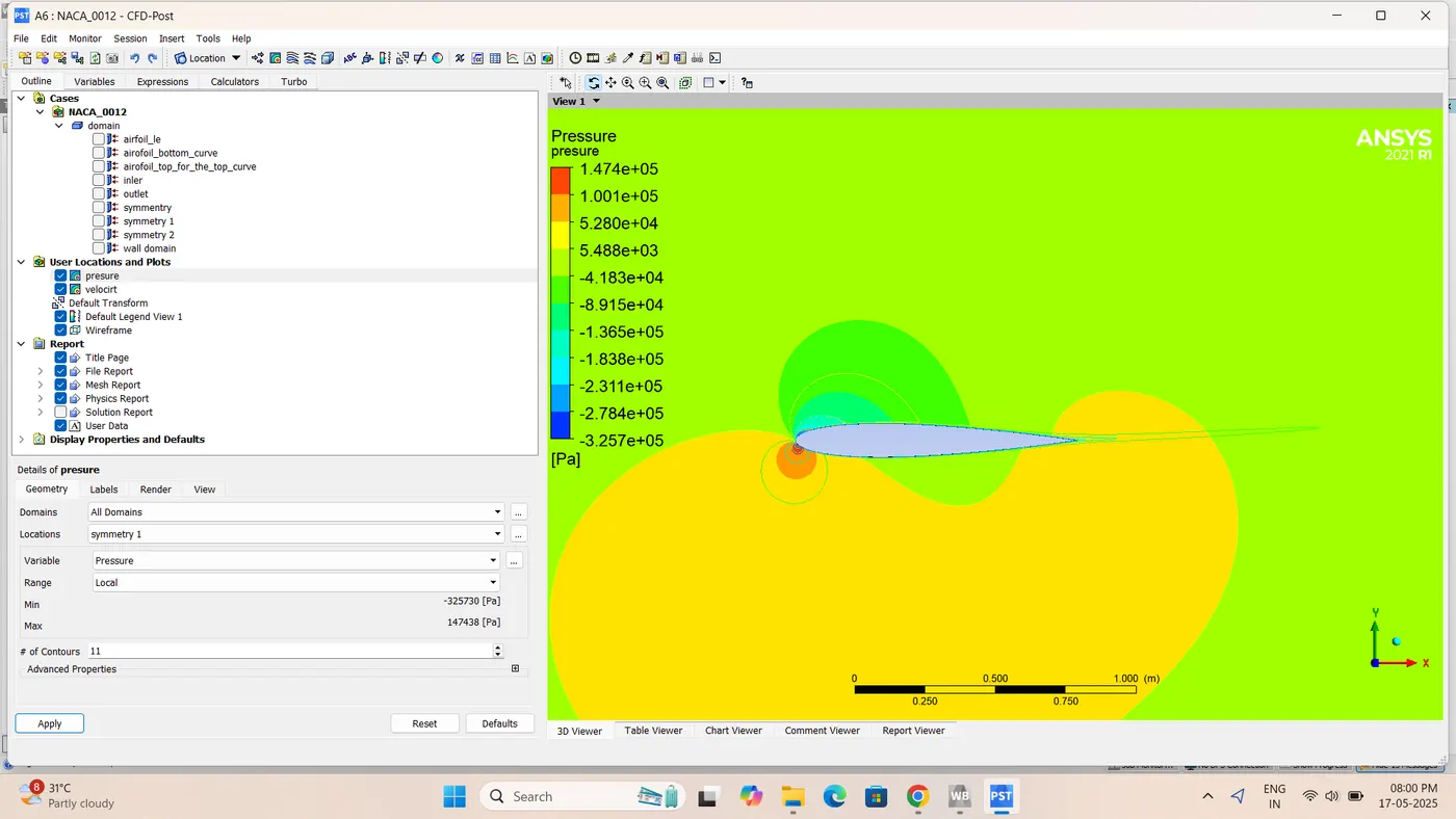
:-Pressure Contour
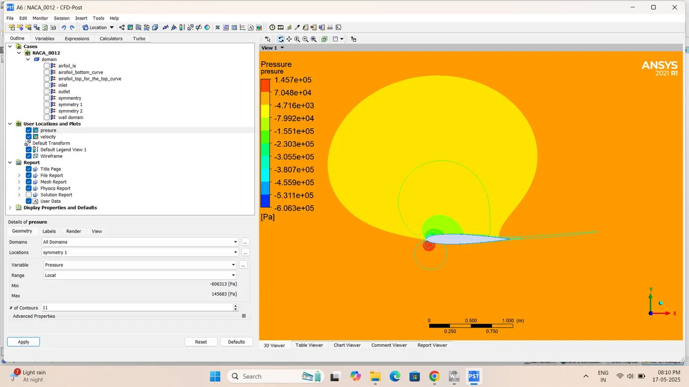
:-compressible 15 angle of attack(V =52m/s) Pressure Contour
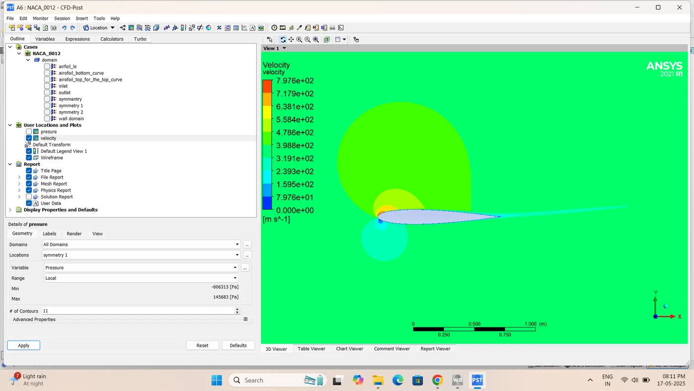
:-Pressure Contour
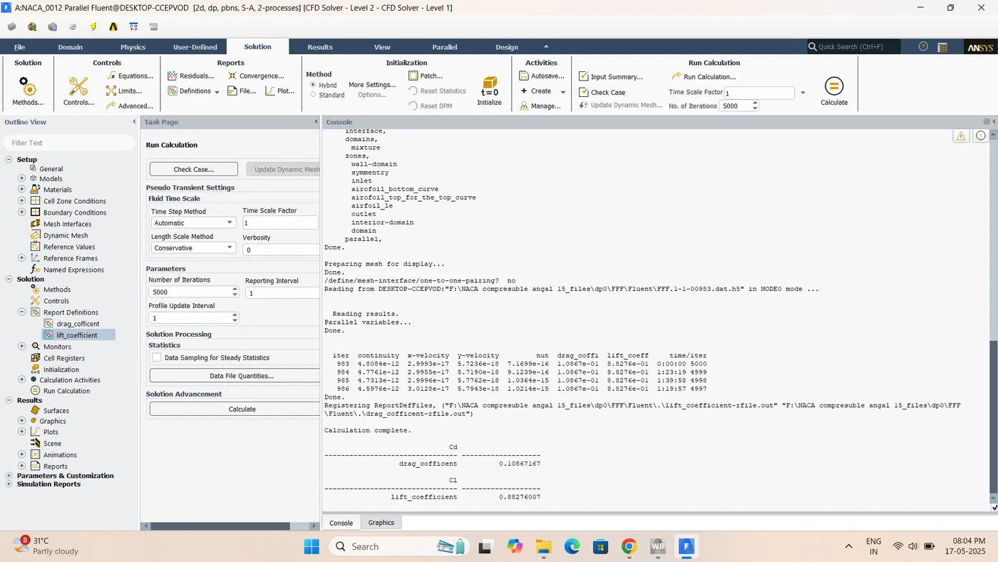
:-Cl lift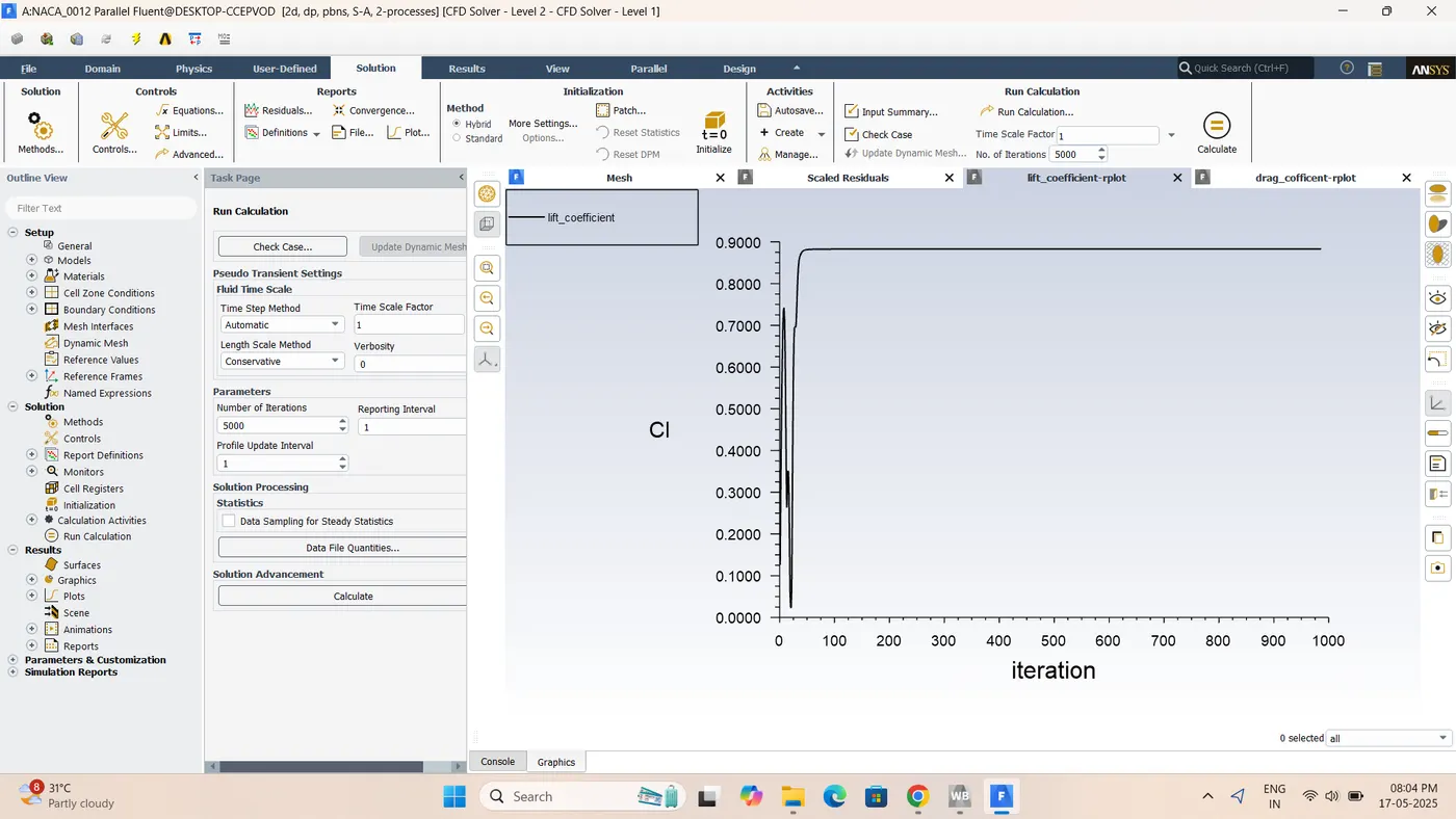
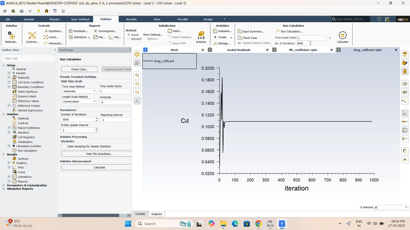
:-Cd Drag
:-Results
| Case | velocity m/s | AoA | Cl | Cd |
|---|
| 1 | 52 | 0° | -5.7818575e-31 | 8.8294723e-31 |
| 2 | 52 | 5° | 0.30245817 | 0.020224649 |
| 3 | 52 | 10° | 0.59255639 | 0.054653807 |
| 4 | 52 | 15° | 0.87182504 | 0.11016623 |
| Case | velocity m/s | AoA | Cl | Cd |
|---|
| 1 | 374.33 | 0° | 8.6874533e-05 | 0.006647141 |
| 2 | 374.33 | 5° | 0.30539873 | 0.018131729 |
| 3 | 374.33 | 10° | 0.60171718 | 0.053440447 |
| 4 | 374.33 | 15° | 0.88276007 | 0.10867167 |
Conclusion
The computational analysis of the NACA 0012 airfoil under both subsonic (incompressible) and supersonic (compressible) flow regimes led to the following key insights:
-
Symmetry and Lift at 0° AoA
-
As a symmetric airfoil, NACA 0012 produces zero net lift at a zero angle of attack (AoA).
-
-
Lift Increases with AoA Until Stall
-
The lift coefficient (Cl) increases with AoA due to enhanced pressure difference across the airfoil.
-
However, this trend reverses beyond a critical AoA (~15°), where lift begins to decrease, indicating stall onset.
-
-
Higher Aerodynamic Forces in Compressible Flow
-
Both lift and drag coefficients are higher in compressible flow than in incompressible flow, due to the impact of shock waves and compressibility effects at high speeds.
-
-
Stall Characteristics
-
Stall occurs when flow separation intensifies and shifts forward toward the leading edge.
-
This results in a sudden drop in lift and a sharp increase in drag, degrading airfoil performance.
-
-
Drag Behavior with AoA
-
The drag coefficient (Cd) consistently increases with AoA, primarily due to growing flow separation and pressure drag.
-
-
Independence of Critical AoA from Flow Speed
-
The critical angle of attack remains constant (~15°) for both low and high velocity cases, indicating it is a function of airfoil geometry, not flow speed.
-