Week 7-Long Piston With Cam
AIM :
To Performing a transient structrual simulation for Long pistion reciprocating with cam.
OBJECTIVES :
Adding & Assigning the appropriate materials to the model.
Create a Contacts & Joint Connections in the model.
Discritize the model.
Applying the Boundary Condition.
INTRODUCTION :
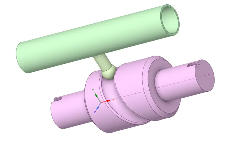
Long pistion with cam mechanism is used for converting the power from rotary motion to Linear or Reciprocating motion. This model is consist of barrel,Long piston with cam follower and cylindrical cam or barrel cam.
A applications are include machine tool drive, reciprocating saws, punching the plate and other few applications.
PROCEDURE FOR ACQUIRING THE OBJECTIVES :
I) CAD Model :
II) Material Adding and Assigning :
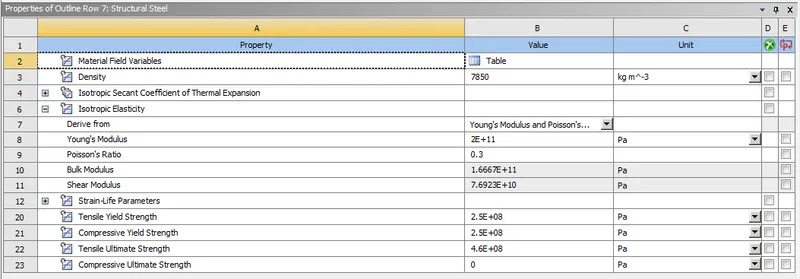
In this simulation, we gonna use Structrual steel as a material for all parts.
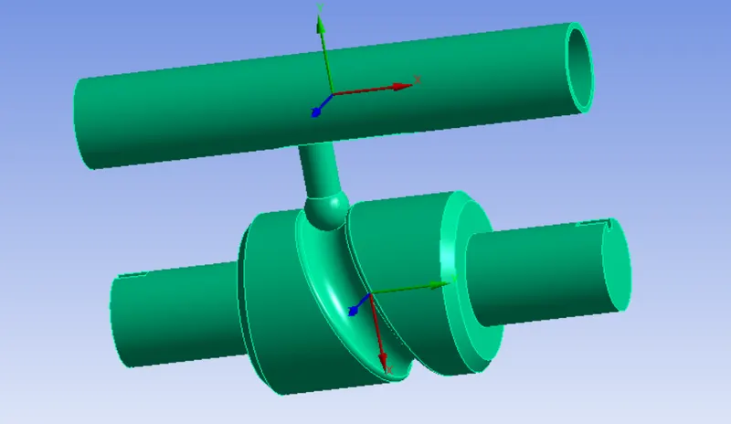
Make Sure, we have to keep stiffness bahavior as "Rigid" for barrel & Cylindrical cam. Because, we just interested to look where contacts between cam follower & Barrel cam.
A New coordinate has been created where centre of mass point like as shown in the below image, once we changed into Rigid instead of flexible.
III) Connections :
We have to defining the connections where individual parts are touching to eachother. In this case, we gonna create two different connectons which are Contact connection & Joint Connection.
i) Contacts :
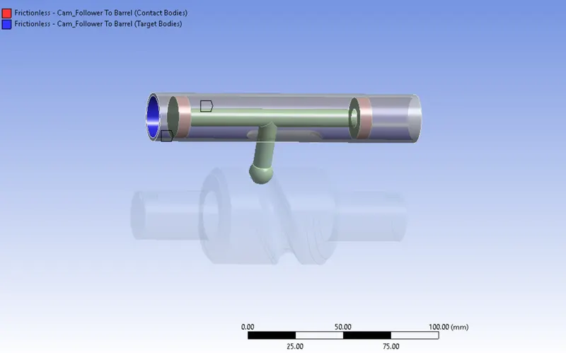
Contacts between Cam Follower to Barrel :
Select the piston contact face as contact bodies & select the barrel inside face as a Target bodies.
For Case 1, a type of contact is "Frictionless" which means there's no frictional force or resistive force between those component.
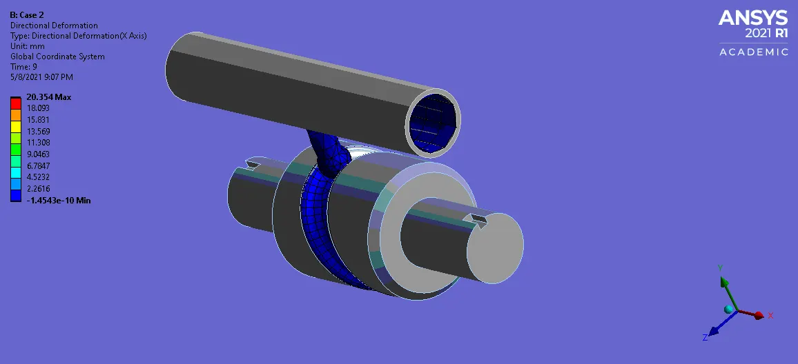
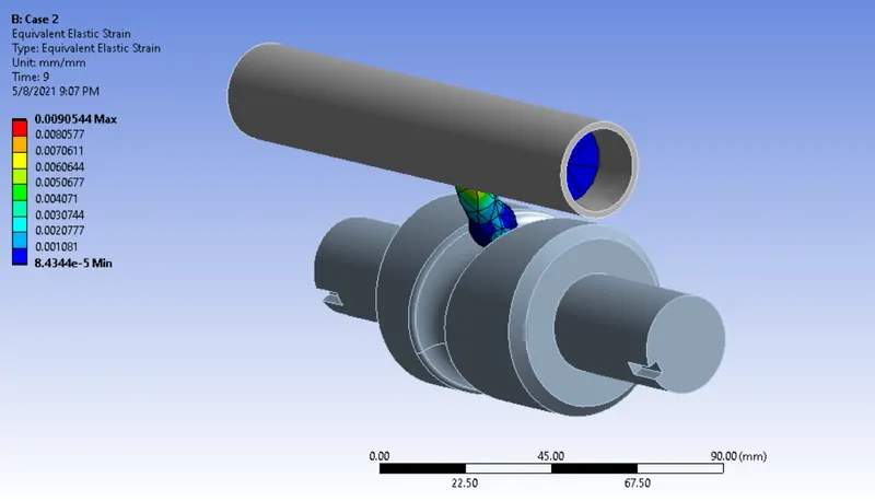
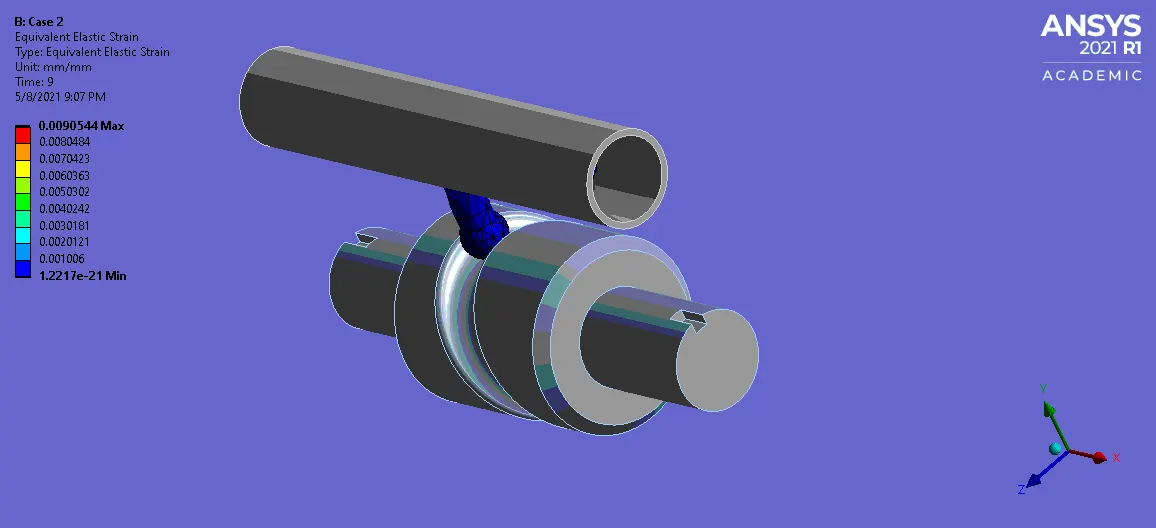
For Case 2, a type of contact is "Frictional" with frictional coefficient is 0.1.
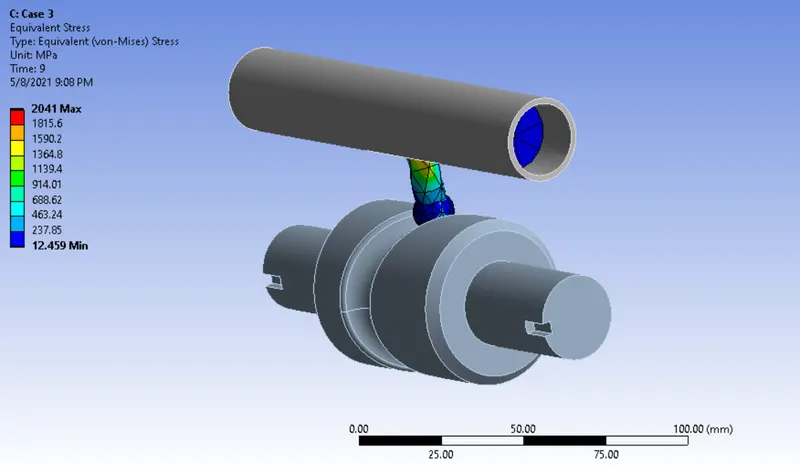
For Case 3, a type of contact is "Frictional" with frictional coefficient is 0.2.
Apart from that, keep default setting options for all cases.
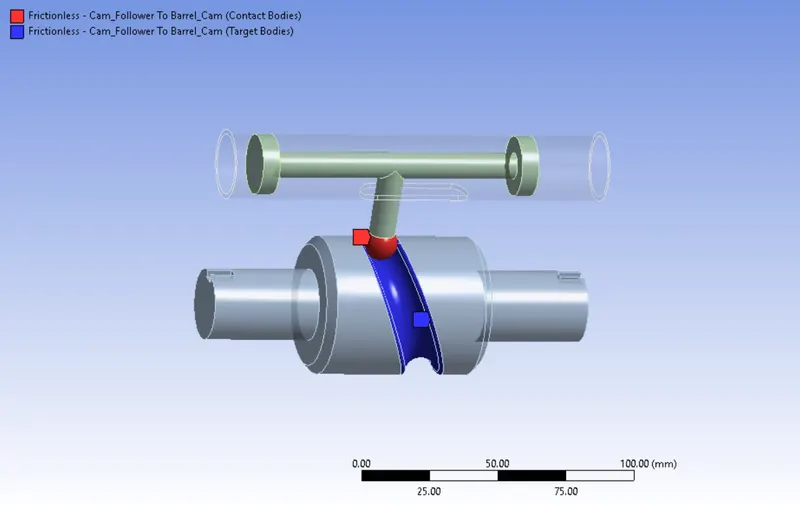
Contacts between Cam Follower to Barrel Cam :
Select the cam follower contact region as a Contact body & Select the groove faces as a target Body like as shown below.
Similarly, we have to defining the type of contact according to the case requirement like as same as how did in previous one.
ii) Joints :
Fixed Joint :
Select the barrel outer face, then fix it by using Fixed joint. Now, barrel has been constrainted in all possible degree of freedoms.
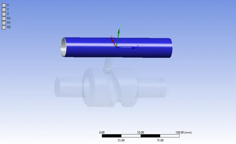
Revolute Joint :
In order to Create a revolute joint for barrel cam, have to selecting the face like as shown in below.
Once created the revolute joint, a barrel cam is to be unconstrainted along the Z Rotational axis alone. Now, barrel cam can able to rotate about an Z axis.
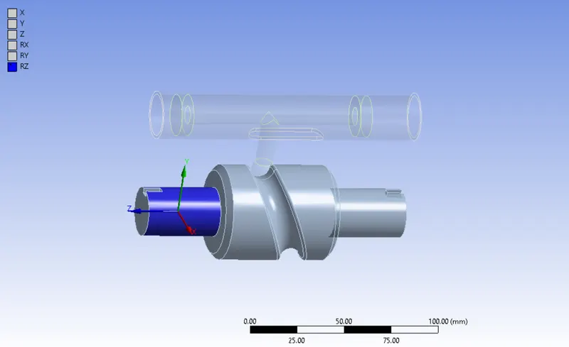
Translational Joint :
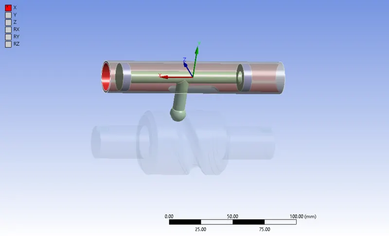
While running the simulation, a long pistion have to be reciprocating where inside the barrel along the x direction. So that, have to unconstraining for barrel & Pistion on their direction
In order to create a translation joint, have to select the barrel inner face as a reference body & piston outer face as a Mobile body like as shown in below.
Once created the translation joint, a pistion & barrel are to be Unconstraint along the x translation axis alone. Now, piston can able to reciprocate along the x direction.
IV) Meshing :
To Split the geometry into finite number of elements that are connected together with nodes, this process is called discretization and that framework or rather let's say collection of nodes and elements is defined by whole model is called meshing. This Finite element method is widely used for solving partial differential equation in different physical field such as Structural problem, Heat transfer problem, Fluid flow problem, Electro magnetic Analysis & Acoustics Analysis.
Face Sizing :
In order to capturing the result accuracy on between cam follower & Barrel cam. Further, have to refine the mesh by using Face sizing with the element size of 3 mm. By this way, we can capture the accurate result in the post processing stage.
Make sure change into "No" for Adapative sizing.
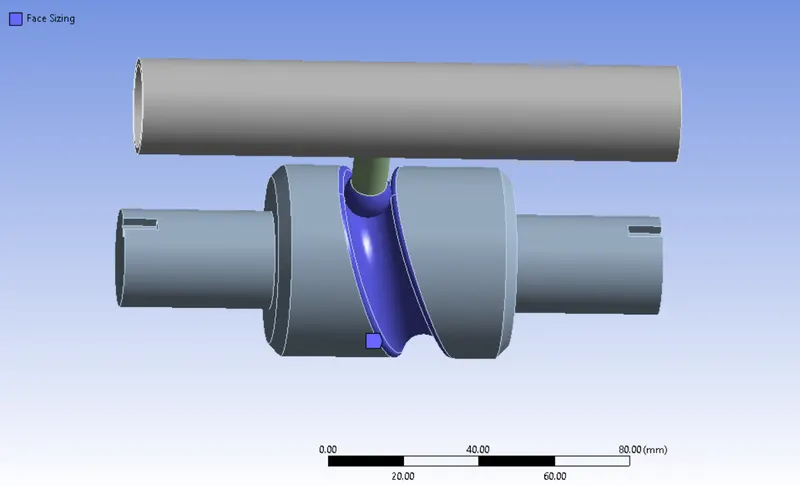
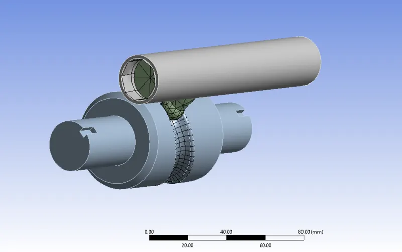
As we know that, we had been changed to rigid behavoir for Barrel & Barrel cam. So that, meshing process is not taken over the whole component, have to be make a surface mesh with mixed type of elements where components are connected together.
Number of Nodes = 2873
Number of Elements = 1074
A Cam Follower is meshed with Tetrahedral elements.
After meshed the component, it has to be look like as shown in below.
V) Analysis Settings :
We have to be solving this model upto 9 number of time steps.
For first time step,
Initial time step is 0.1 sec
Minimum Time step is 0.05 sec
Maximum Time Step is 0.2 sec
Switch to "Program Controlled" for Weak Spring.
Switch to "ON" for Large Deflection.
Energy dissipation ratio is 0.1
Switch to "Yes" for Activation for first substep.
Switch to "Yes" for all options except "General Miscellaneous" option which are comes below in the "Output controls" setting.
For 2 - 9 time steps,
Initial time step is 0.1 sec
Minimum Time step is 0.05 sec
Maximum Time Step is 0.3 sec
Apart from time steps, keep all options are to be same as which provided in the previous time step.
Boundary Conditions :
Rotational Joint :
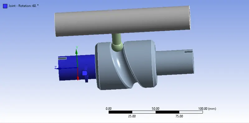
Select "Ground to Barrel cam" for type of joint, followingly select "Rotational" for type of definition.
In this case, we has to be rotating the barrel cam from 0 degree to 270 degree with the equal interval of 9 steps.
RESULTS :
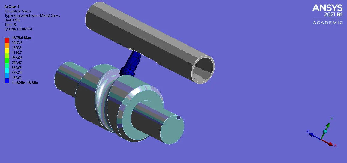
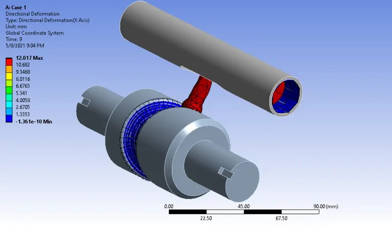
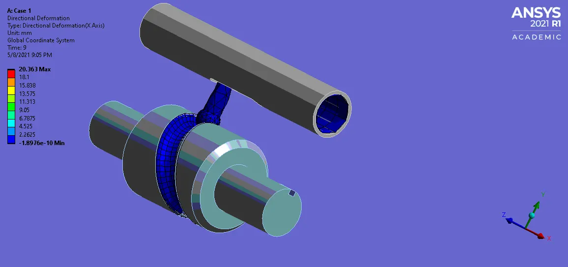
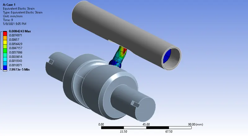
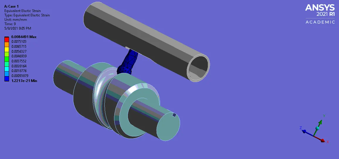
Case 1 :
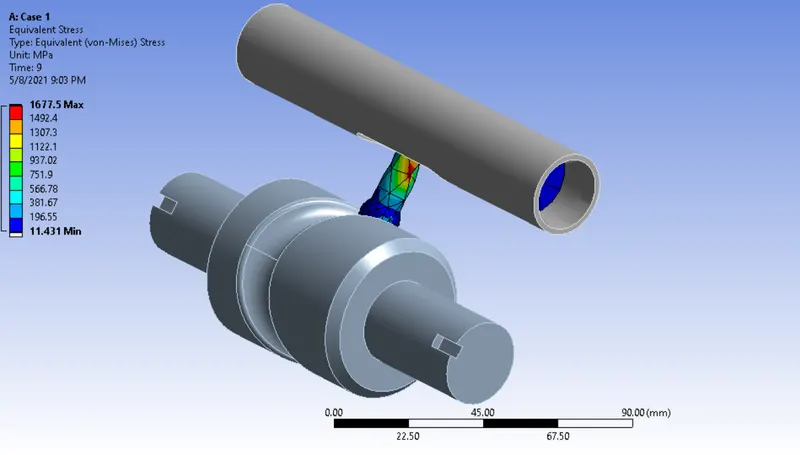
Equivalent Stress :
Directional Deformation :
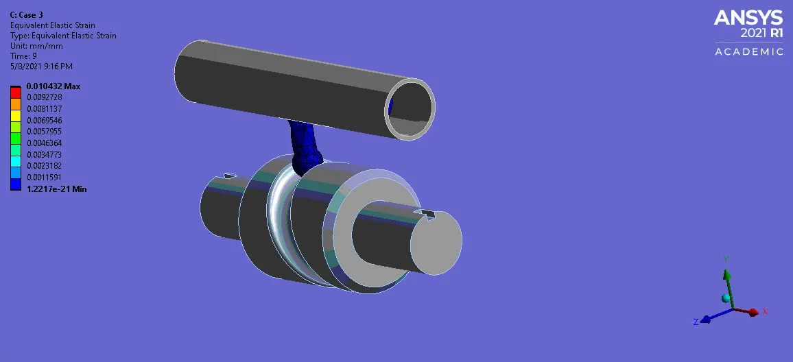
Equivalent Elastic Strain :
Case 2 :
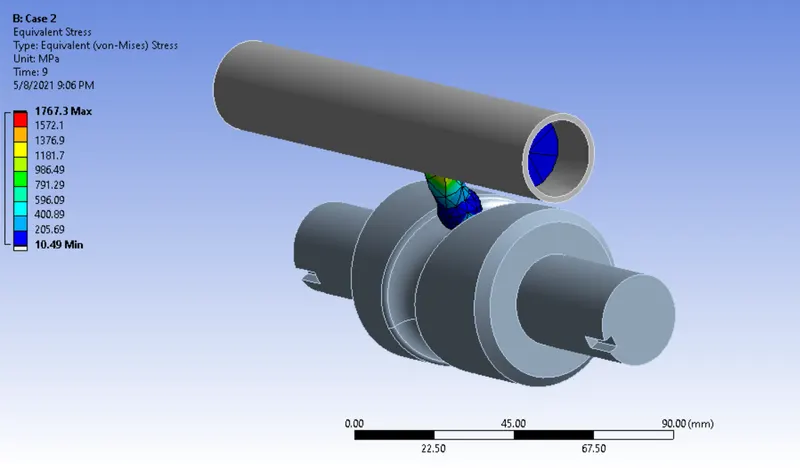
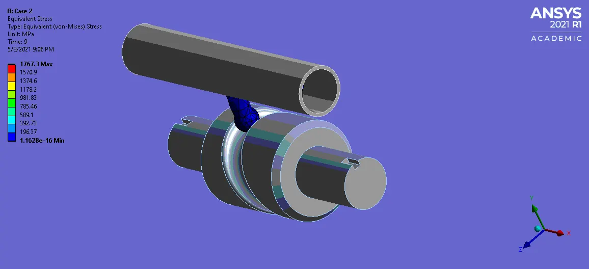
Equivalent Stress :
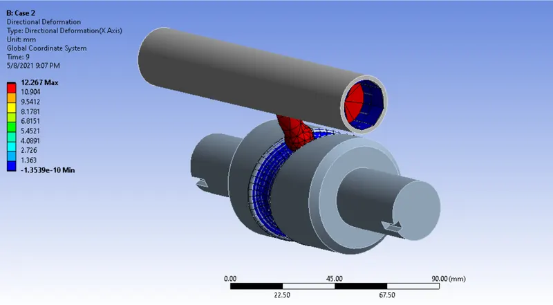
Directional Deformation :
Equivalent Elastic Strain :
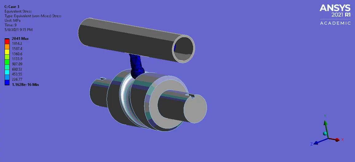
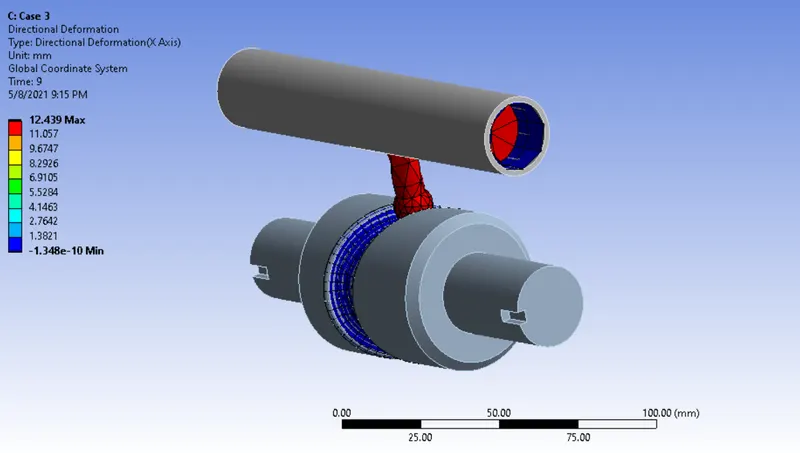
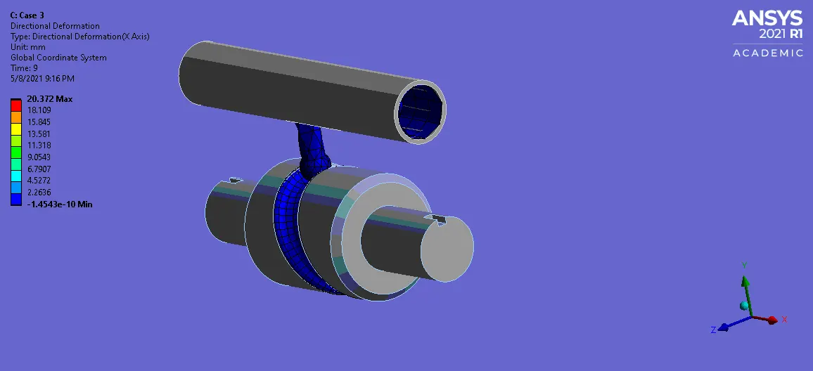
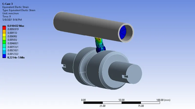
Case 3 :
Equivalent Stress :
Directional Deformation :
Equivalent Elastic Strain :
CONCLUSION :
| Cases\Field Variables | Frictional Coefficient between contacts | Equivalent Stress in Mpa | Equivalent Elastic Strain in mm | Directional Deformation in mm |
| Case 1 | 0 | 1677.5 | 0.00842 | 12.017 |
| Case 2 | 0.1 | 1767.3 | 0.009054 | 12.267 |
| Case 3 | 0.2 | 2041 | 0.01043 | 12.439 |
A field Variables like stress, strain & deformation are directly proprotional to coefficient of friction. Because if frictional force have been increased, by result we have to apply more force for which overcome the frictional force, that will lead to increase the stress value.
Learning Outcome :
I Learnt How to reduce the computational calculate time & storage space by changed into Rigid behavior.
I Learnt How to setup the Analysis setting for this model.
I Learnt significance of frictional coefficient from this simulation results