Title : Transient analysis on a piston and cam mechanism model.
Objective : To calculate stresses in the cam follower for varying frictonal coefficient between cam follower and barrel cam.
Model:
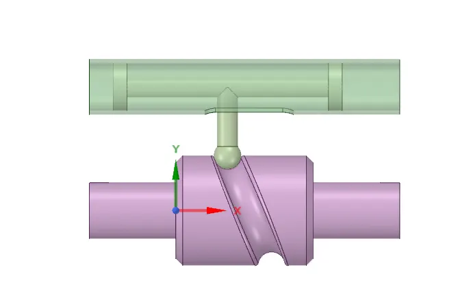
Contacts :
cam follower to barrel : frictionless
cam follower to barrel cam : 1)frictionless 2) frictional(0.1) 3)frictional(0.2)
Joints :
Body to ground fixed : Barrel
Body to ground revolute : Barrel cam
Body to body translational : Cam follower
Mesh Data :
| Object Name |
Mesh |
| State |
Solved |
| Display |
| Display Style |
Use Geometry Setting |
| Defaults |
| Physics Preference |
Mechanical |
| Solver Preference |
Mechanical APDL |
| Element Order |
Program Controlled |
| Element Size |
Default |
| Sizing |
| Use Adaptive Sizing |
Yes |
| Resolution |
Default (2) |
| Mesh Defeaturing |
Yes |
| Defeature Size |
Default |
| Transition |
Fast |
| Span Angle Center |
Coarse |
| Initial Size Seed |
Assembly |
| Bounding Box Diagonal |
179.61 mm |
| Average Surface Area |
1166.9 mm² |
| Minimum Edge Length |
1.9027 mm |
| Quality |
| Check Mesh Quality |
Yes, Errors |
| Error Limits |
Aggressive Mechanical |
| Target Quality |
Default (0.050000) |
| Smoothing |
Medium |
| Mesh Metric |
None |
| Inflation |
| Use Automatic Inflation |
None |
| Inflation Option |
Smooth Transition |
| Transition Ratio |
0.272 |
| Maximum Layers |
5 |
| Growth Rate |
1.2 |
| Inflation Algorithm |
Pre |
| View Advanced Options |
No |
| Advanced |
| Number of CPUs for Parallel Part Meshing |
Program Controlled |
| Straight Sided Elements |
No |
| Rigid Body Behavior |
Dimensionally Reduced |
| Rigid Face Mesh Type |
Quad/Tri |
| Triangle Surface Mesher |
Program Controlled |
| Topology Checking |
Yes |
| Pinch Tolerance |
Please Define |
| Generate Pinch on Refresh |
No |
| Statistics |
| Nodes |
5762 |
| Elements |
2136 |
TABLE 12
Model (D4) > Mesh > Mesh Controls
| Object Name |
Face Sizing |
| State |
Fully Defined |
| Scope |
| Scoping Method |
Geometry Selection |
| Geometry |
7 Faces |
| Definition |
| Suppressed |
No |
| Type |
Element Size |
| Element Size |
2.0 mm |
| Advanced |
| Defeature Size |
Default |
| Influence Volume |
No |
| Behavior |
Soft |
Analysis settings :
TABLE 13
Model (D4) > Analysis
| Object Name |
Transient (D5) |
| State |
Solved |
| Definition |
| Physics Type |
Structural |
| Analysis Type |
Transient |
| Solver Target |
Mechanical APDL |
| Options |
| Environment Temperature |
22. °C |
| Generate Input Only |
No |
TABLE 14
Model (D4) > Transient (D5) > Initial Conditions
| Object Name |
Initial Conditions |
| State |
Fully Defined |
TABLE 15
Model (D4) > Transient (D5) > Initial Conditions > Initial Condition
| Object Name |
Modal (None) |
| State |
Fully Defined |
| Definition |
| Modal Environment |
None Available |
| Pre-Stress Environment |
None |
TABLE 16
Model (D4) > Transient (D5) > Analysis Settings
| Object Name |
Analysis Settings |
| State |
Fully Defined |
| Step Controls |
| Number Of Steps |
9. |
| Current Step Number |
2. |
| Step End Time |
2. s |
| Auto Time Stepping |
On |
| Define By |
Time |
| Carry Over Time Step |
Off |
| Initial Time Step |
0.1 s |
| Minimum Time Step |
5.e-002 s |
| Maximum Time Step |
0.3 s |
| Time Integration |
On |
| Solver Controls |
| Solver Type |
Program Controlled |
| Weak Springs |
Program Controlled |
| Large Deflection |
On |
| App. Based Settings |
Moderate Speed Dynamics |
| Restart Controls |
| Generate Restart Points |
Program Controlled |
| Retain Files After Full Solve |
No |
| Combine Restart Files |
Program Controlled |
| Nonlinear Controls |
| Newton-Raphson Option |
Program Controlled |
| Force Convergence |
Program Controlled |
| Moment Convergence |
Program Controlled |
| Displacement Convergence |
Program Controlled |
| Rotation Convergence |
Program Controlled |
| Line Search |
Program Controlled |
| Stabilization |
Constant |
| --Method |
Energy |
| --Energy Dissipation Ratio |
0.1 |
| --Activation For First Substep |
Yes |
| --Stabilization Force Limit |
0.2 |
| Advanced |
| Contact Split (DMP) |
Off |
| Output Controls |
| Stress |
Yes |
| Surface Stress |
Yes |
| Back Stress |
Yes |
| Strain |
Yes |
| Contact Data |
Yes |
| Nonlinear Data |
Yes |
| Nodal Forces |
Yes |
| Volume and Energy |
Yes |
| Euler Angles |
Yes |
| General Miscellaneous |
No |
| Contact Miscellaneous |
Yes |
| Store Results At |
All Time Points |
| Result File Compression |
Program Controlled |
| Damping Controls |
| Stiffness Coefficient Define By |
Direct Input |
| Stiffness Coefficient |
0. |
| Mass Coefficient |
0. |
| Analysis Data Management |
| Solver Files Directory |
C:\Users\utk32\Documents\long piston cam_files\dp0\SYS-3\MECH\ |
| Future Analysis |
None |
| Scratch Solver Files Directory |
|
| Save MAPDL db |
No |
| Contact Summary |
Program Controlled |
| Delete Unneeded Files |
Yes |
| Nonlinear Solution |
Yes |
| Solver Units |
Active System |
| Solver Unit System |
nmm |
Results:
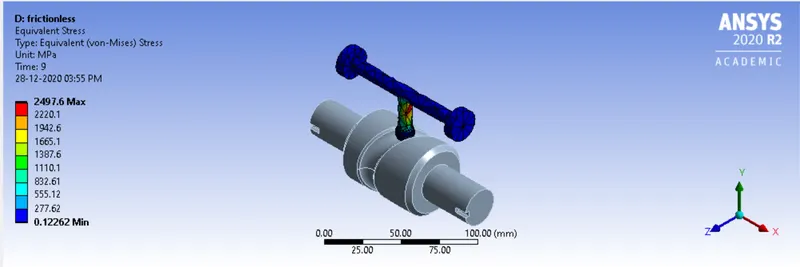
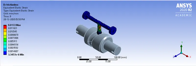
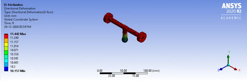
Case 1 : frictionless
Equivalent stress :
Equivalent strain :
Directional deformation:
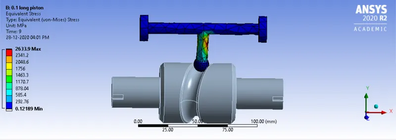
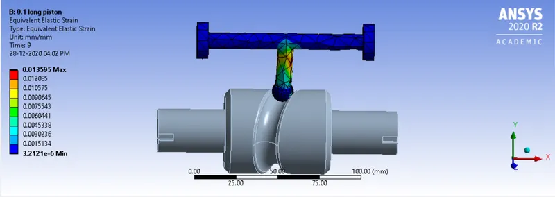
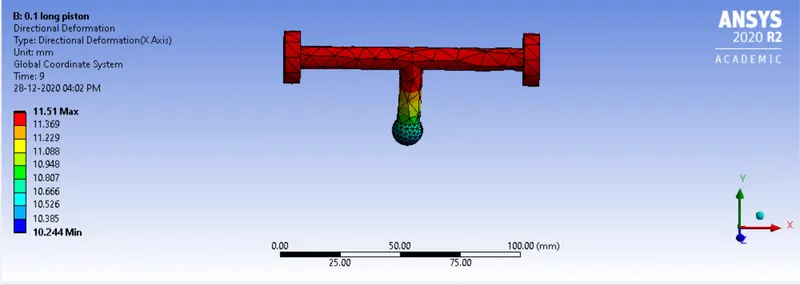
Case 2 : frictional - 0.1
Equivalent stress :
Equivalent strain :
Directional deformation:
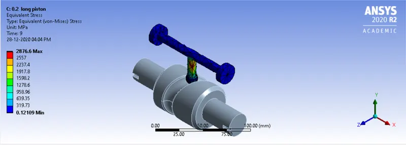
Case 3 : frictional - 0.2
Equivalent stress :
Equivalent strain :
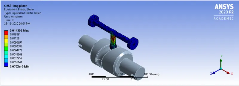
Directional deformation:
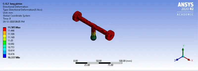
Table :
| |
case 1 Frictionless |
case 2 Frictional(0.1) |
case 3 Frictional(0.2) |
| Equivalent stress(MPa) |
2497.6-0.12262 |
2633.9-0.12189 |
2876.6-0.12109 |
| Equivalent elastic strain |
0.0133-3.34e-6 |
0.0135-3.21e-6 |
0.0145 - 3.07e-6 |
| Directional Deformation(mm) |
11.442-10.157 |
11.51-10.244 |
11.585 -10.337 |
Inference : As the frictional coefficient is increased from 0 to 0.1 to 0.2 the stress in cam follower increases. The reason for this is reactional frictional force caused due to the relative movement between barrel cam and cam follower. This reactional force adds on to the existing translational force and generates stress. To reduce the generated stress the surface between cam follower and barrel cam needs to be as smooth as possible to reduce the coefficient of friction.