Week 7-Long Piston With Cam
AIM: - PERFORM A TRANSIENT SIMULATION ON A PISTON AND CAM MECHANISM MODEL.
Objectives:
Perform the analysis for three different Friction values:
Frictionless
Friction Coefficient = 0.1
Friction Coefficient = 0.2
Find out the Equivalent Stress, Directional Deformation, and Equivalent Strain for each case and compare them for all three cases.
To begin the analysis, select the Transient Structural Analysis from the Analysis Systems.
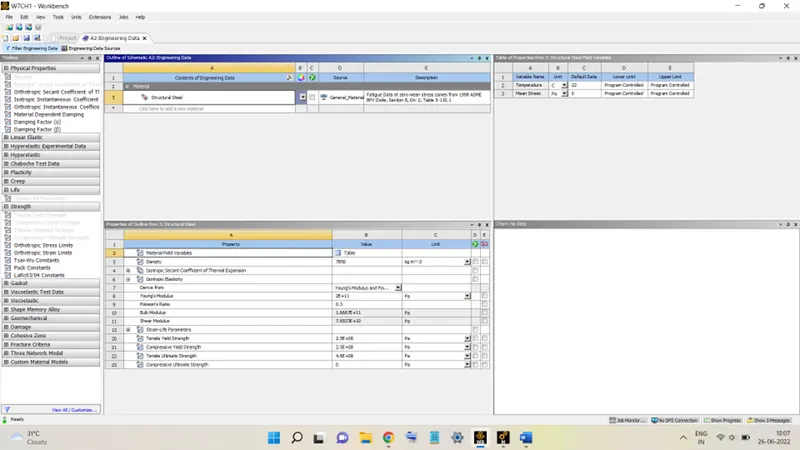
The material used in this analysis will be Structural Steel for all the parts. The properties of Structural Steel are mentioned below:
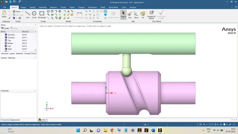
Next, import the geometry into the project environment, the geometry looks like this in SpaceClaim:
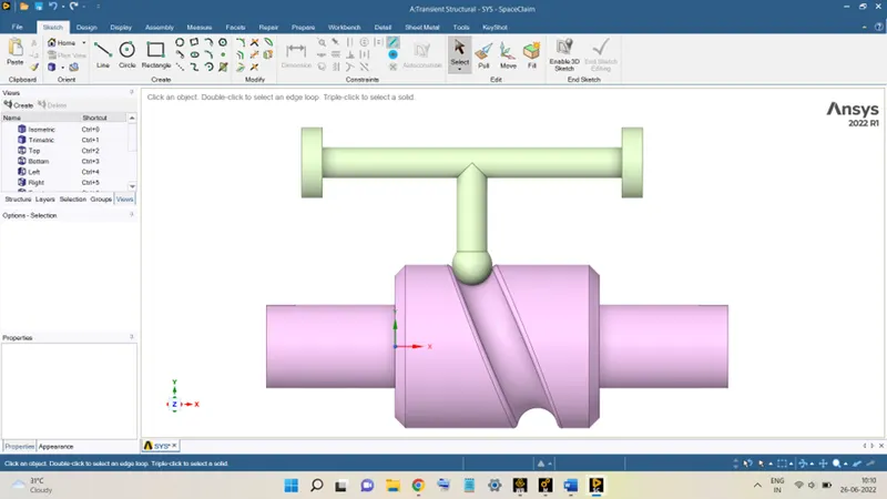
Launch the Mechanical Module by right-clicking on Model and selecting Edit. In the module, first, rename all the parts:
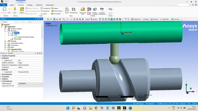
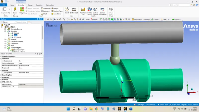
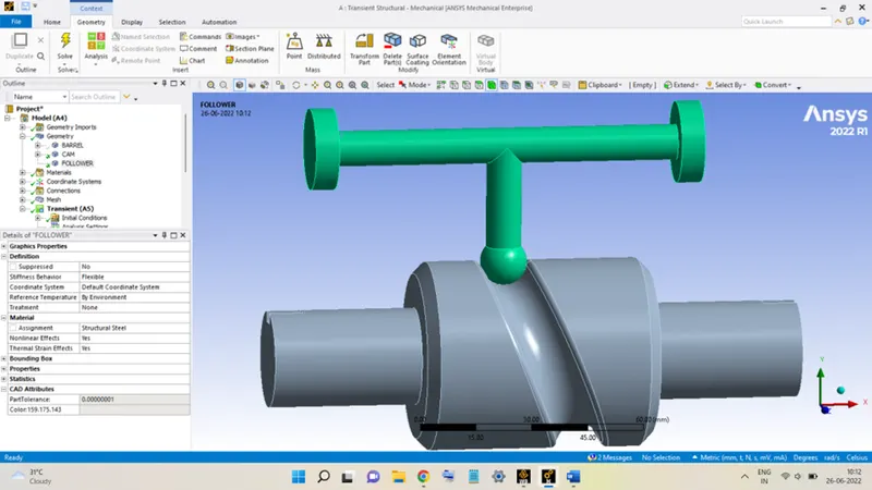
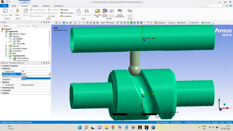
Select BARREL and CAM and convert their Stiffness Behavior to Rigid.
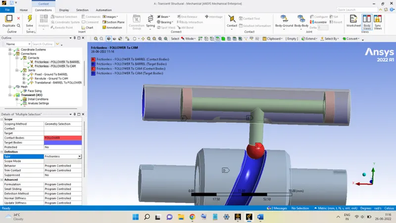
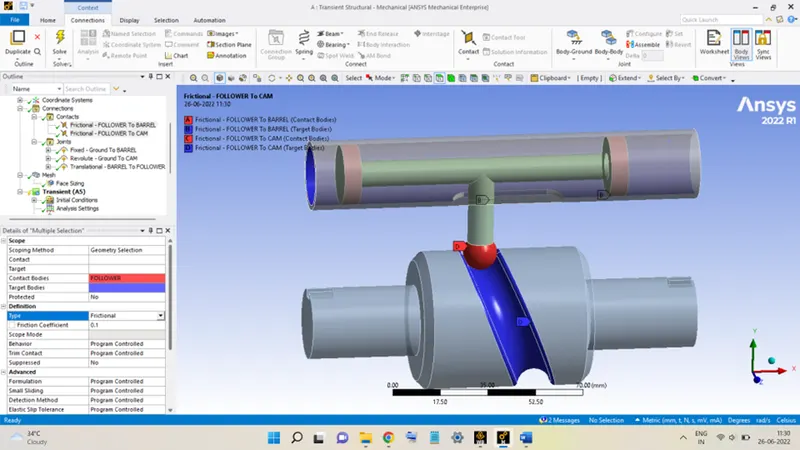
The next step is to add contacts to the model. There are two contacts present:
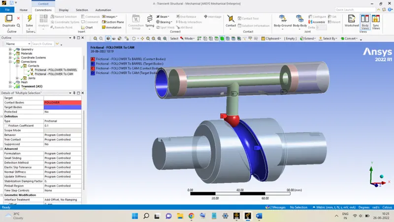
1. FOLLOWER to BARREL: The FOLLOWER will slide inside the BARREL.
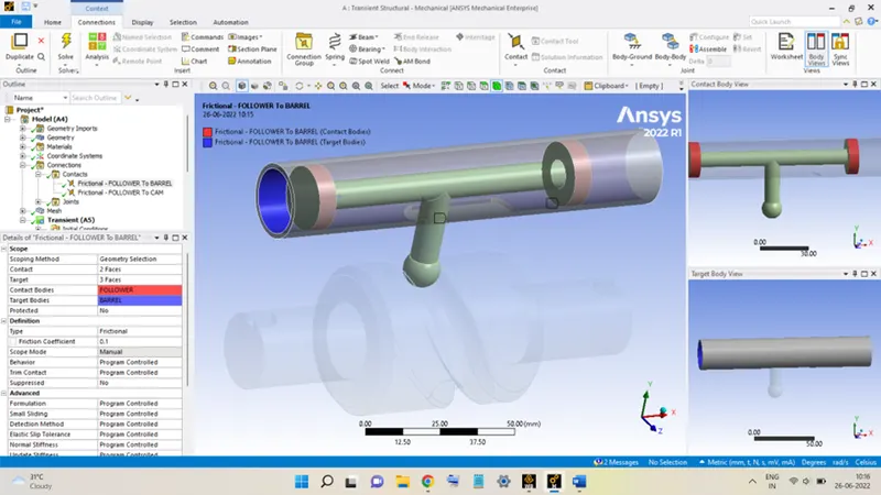
2. FOLLOWER to CAM: The FOLLOWER Bob will move according to the groove present in the CAM.
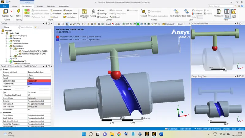
Based on the type of contact there will be three cases:
a) The first is when the contacts are Frictionless.
b) Second both contacts are Frictional, with a Friction Coefficient equal to 0.1.
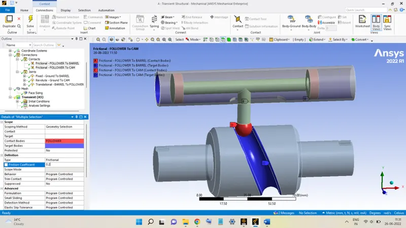
c) Third both contacts are Frictional, with a Friction Coefficient equal to 0.2.
The other contact settings are the same for all the three cases as shown in the figure below:
Adding Joints in the model:
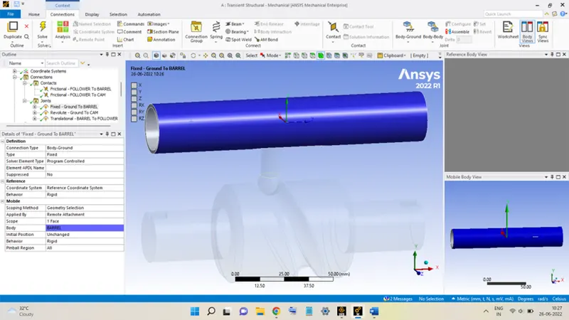
1. BARREL is fixed:
the barrel is supplied with fixed support, shown below:
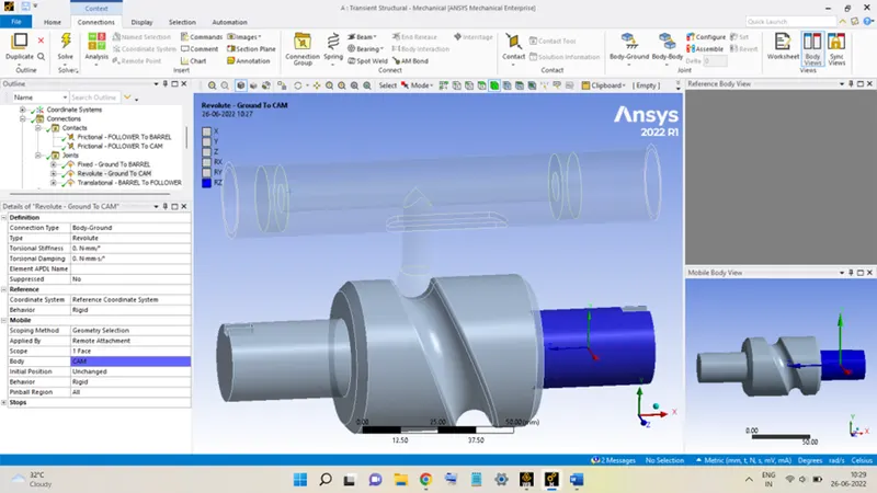
2. Revolute Joint to CAM:
The CAM will revolve around the Z-Axis with the help of the Revolute Body-Ground Joint, as shown in the figure below:
3. Translational Joint to FOLLOWER:
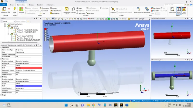
The FOLLOWER will be sliding within the BARREL through a Translational Body – Body Joint with FOLLOWER as Mobile body and BARREL as the Reference body, shown below:
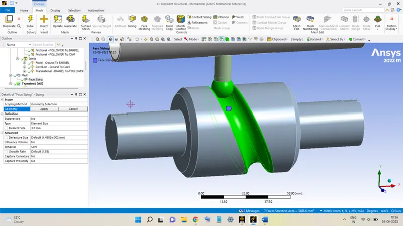
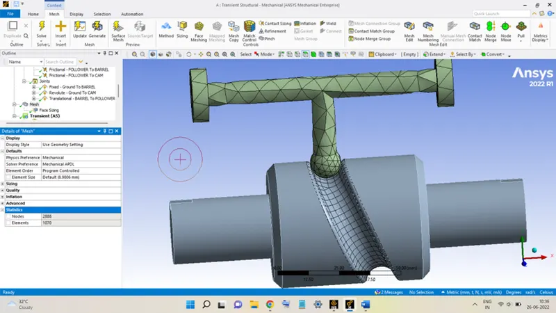
Next is to mesh the model. The meshing will be applicable only on the FOLLOWER body and the groove surface in which it seats. The surfaces of the groove are selected using the Sizing option and the Element Size used is equal to 3 mm.
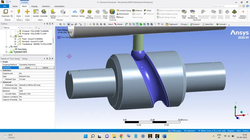
The meshed model will look like this:
Analysis Settings:
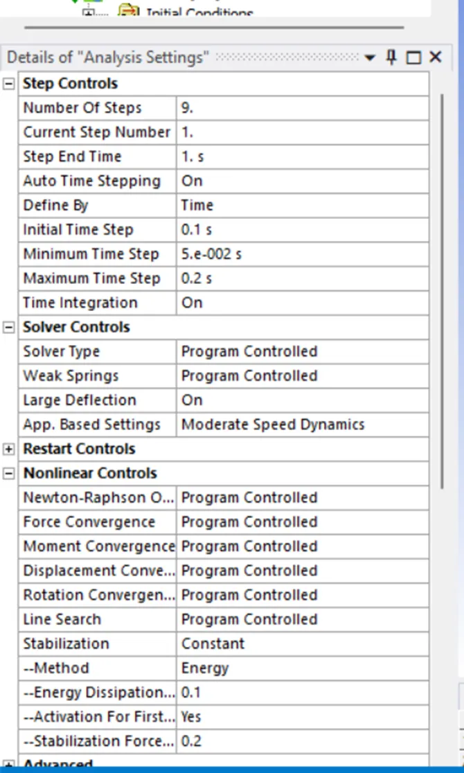
The Number of Steps taken is equal to 9, the analysis settings for the first time step are as follows:
For the rest of the steps the setting is:
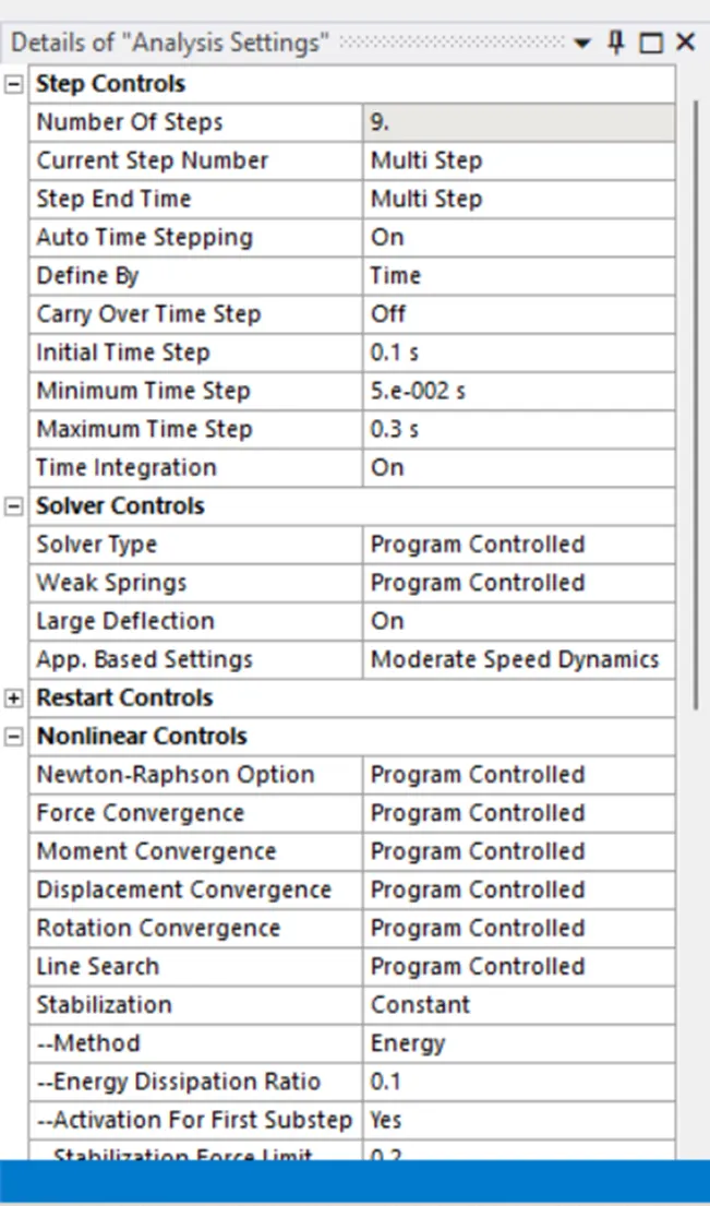
For all the steps, in the Output Controls, all options are taken as Yes except for the Contact Miscellaneous.
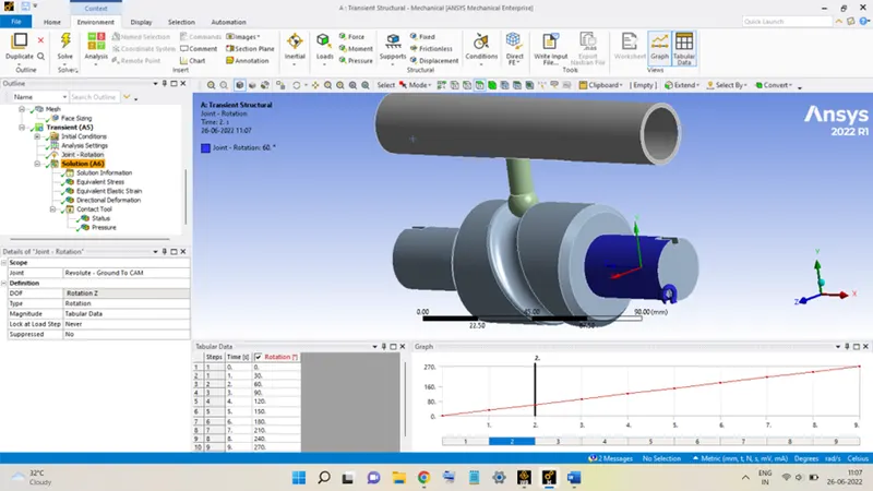
The next step is to add the Joint Loads to the model. The CAM is assigned with a Rotation Joint load about the Z-Axis. The values are submitted in Tabular format as shown below:
Now the model is ready for the analysis, add the necessary output results required from the analysis, and then hit on Solve to start the analysis.
RESULTS:
CASE 1: JOINTS ARE FRICTIONLESS
Equivalent Stress:
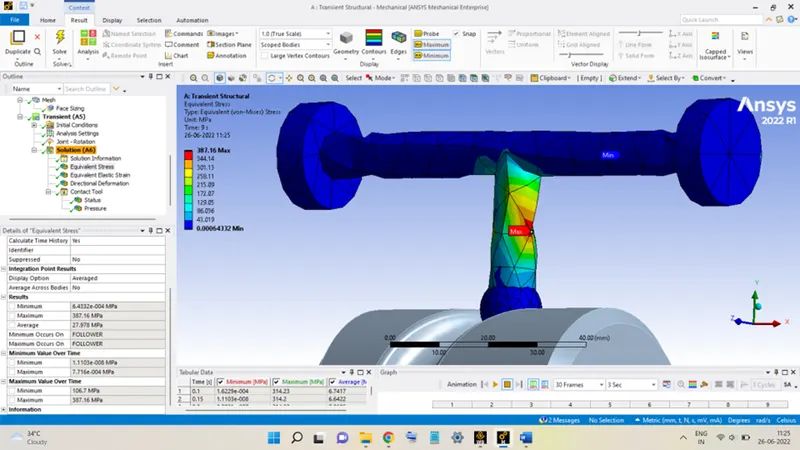
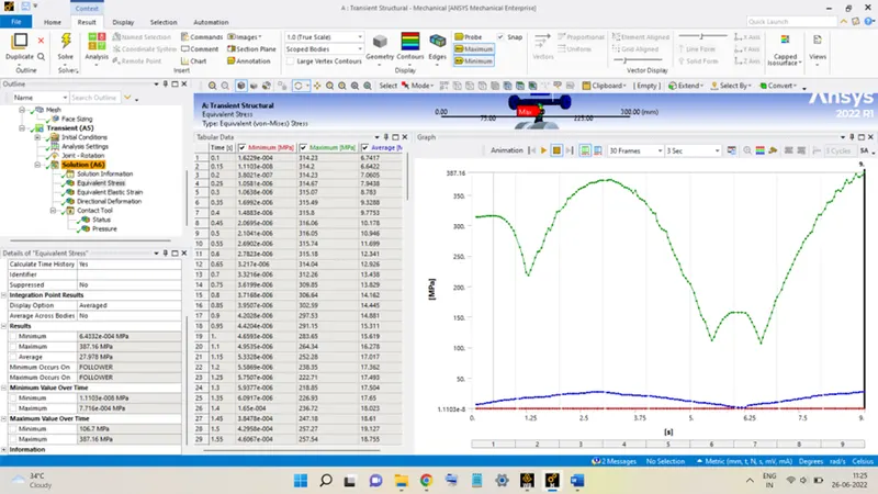
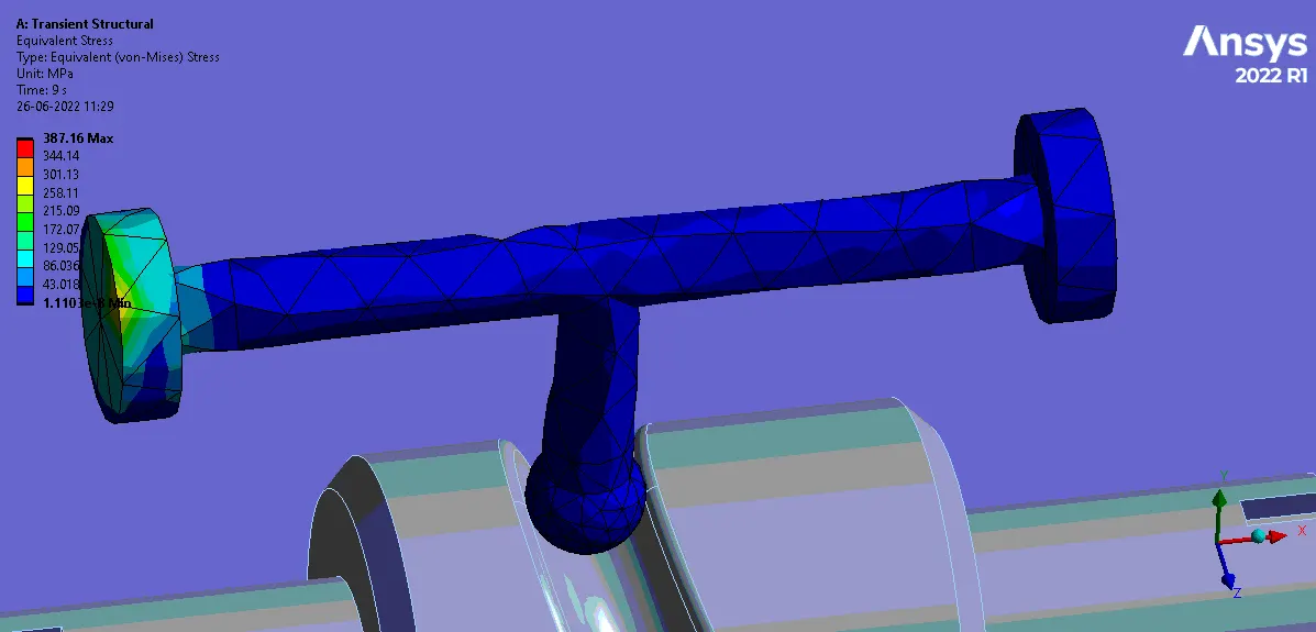
The stress developed in the FOLLOWER during the motion is shown in the figures above. Stress reaches a maximum value of 387.16 MPa.
Equivalent Elastic Strain:
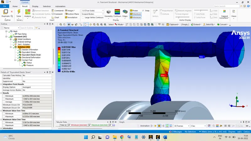
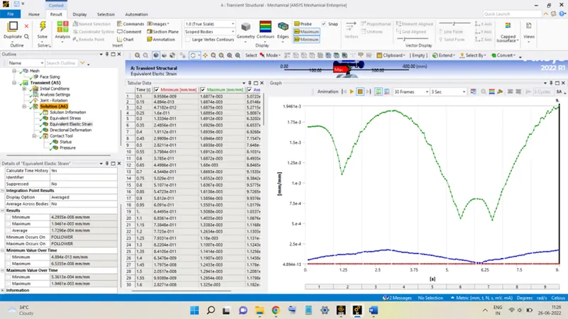
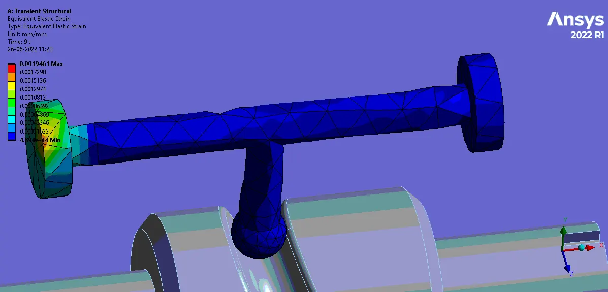
The strain developed in the FOLLOWER during the motion is shown in the figures above. Strain reaches a maximum value of 1.9461 x 10⁻³.
Deformation along Z-Axis:
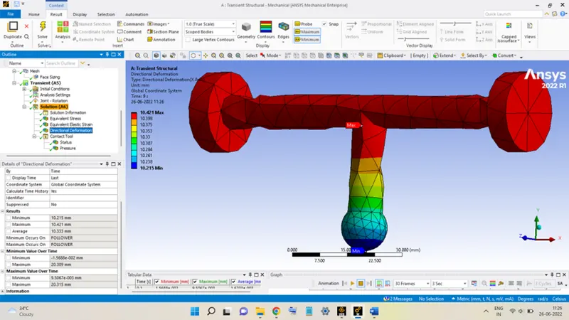
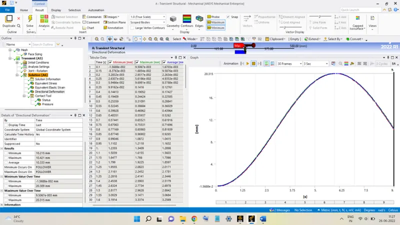
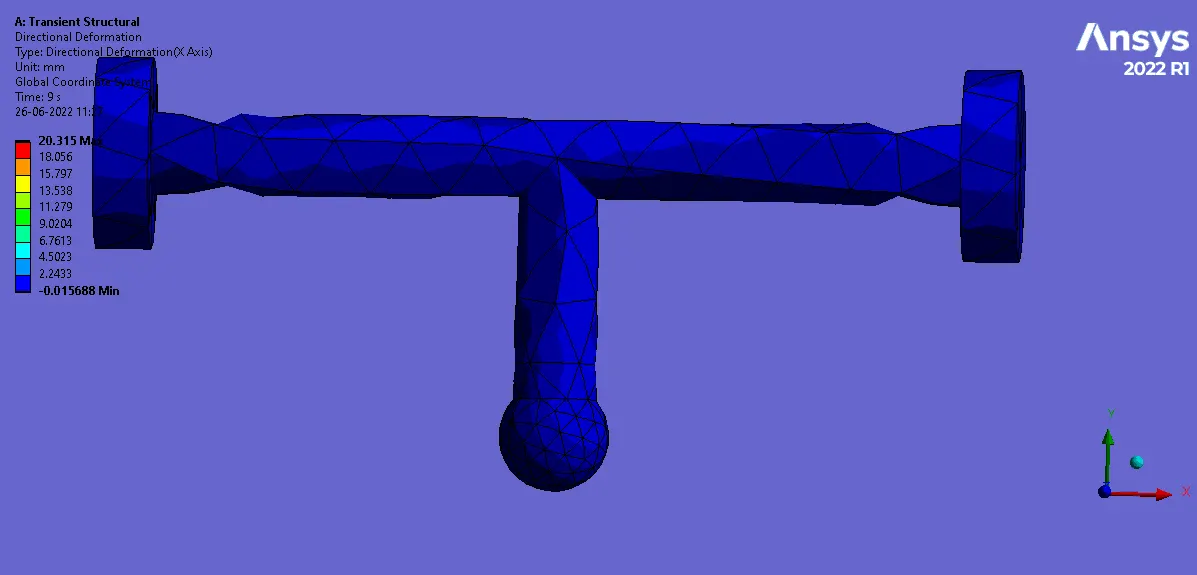
The deformation of the FOLLOWER during the motion is shown above. The maximum displacement of the FOLLOWER is seen to be equal to 20.315 mm.
CASE 2: JOINTS ARE FRICTIONAL, WITH A FRICTION COEFFICIENT EQUAL TO 0.1
Equivalent Stress:
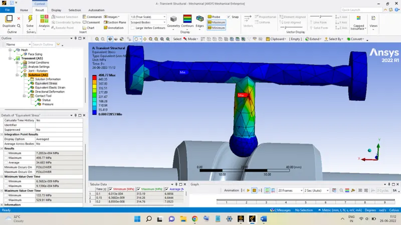
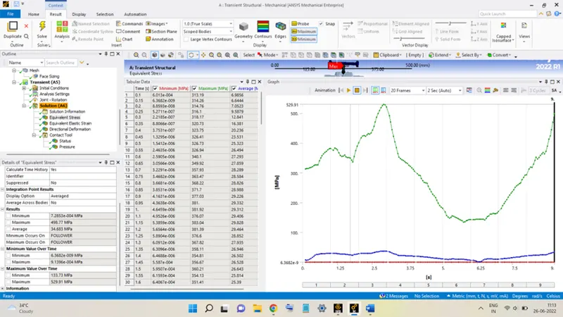
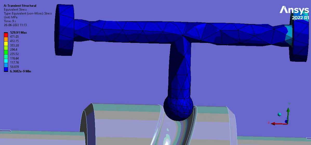
The stress developed in the FOLLOWER during the motion is shown in the figures above. Stress reaches a maximum value of 529.91 MPa.
Equivalent Elastic Strain:
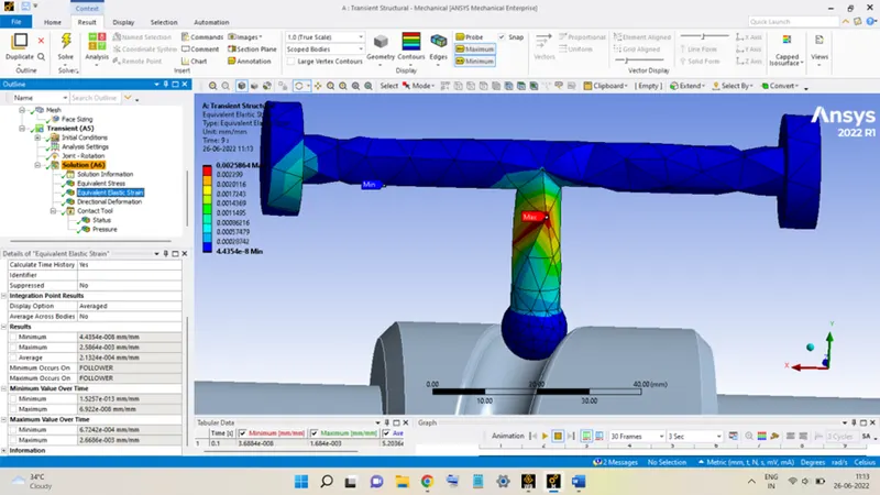
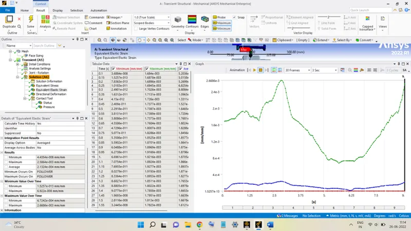
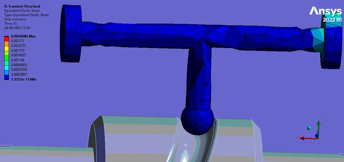
The strain developed in the FOLLOWER during the motion is shown in the figures above. Strain reaches a maximum value of 2.6686 x 10⁻³.
Deformation along Z-Axis:
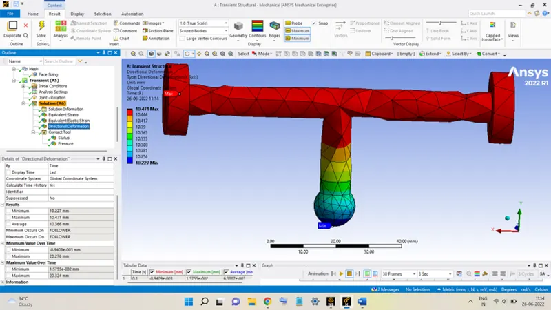
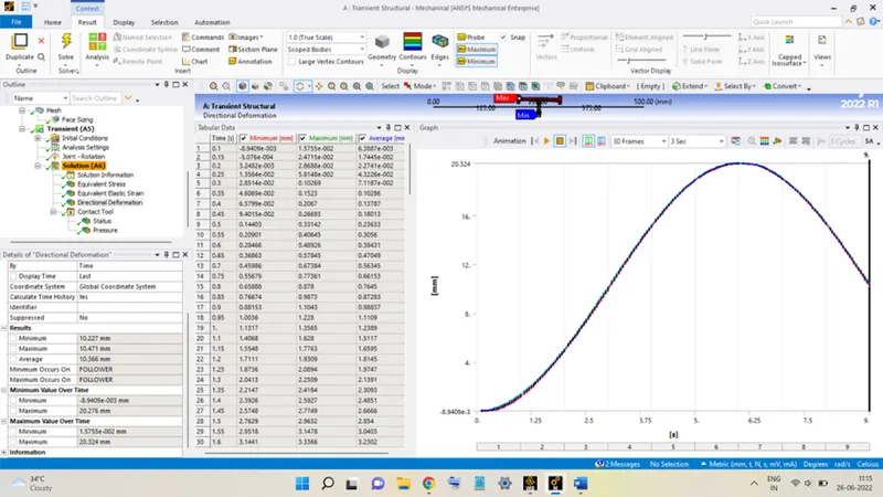
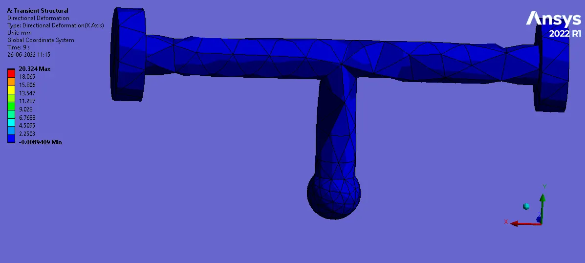
The deformation of the FOLLOWER during the motion is shown above. The maximum displacement of the FOLLOWER is seen to be equal to 20.324 mm.
CASE 3: JOINTS ARE FRICTIONAL, WITH A FRICTION COEFFICIENT EQUAL TO 0.2
Equivalent Stress:
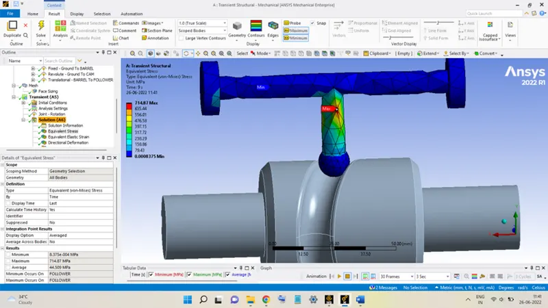
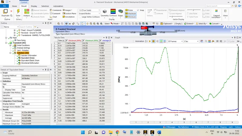
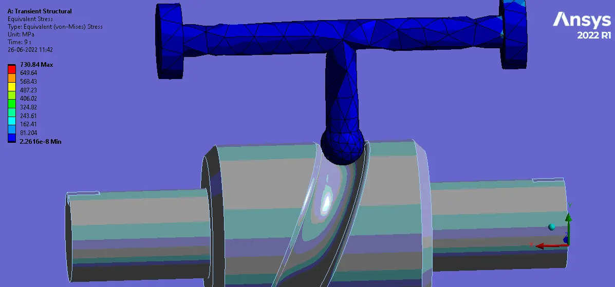
The stress developed in the FOLLOWER during the motion is shown in the figures above. Stress reaches a maximum value of 730.84 MPa.
Equivalent Elastic Strain:
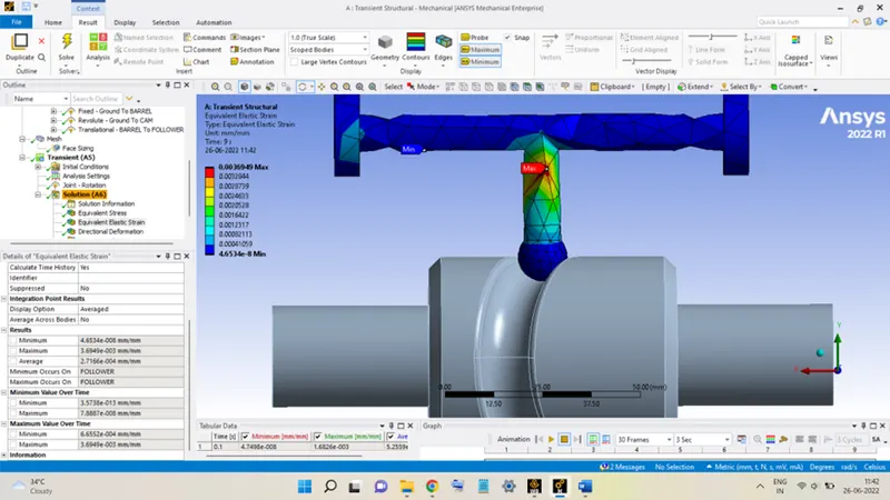
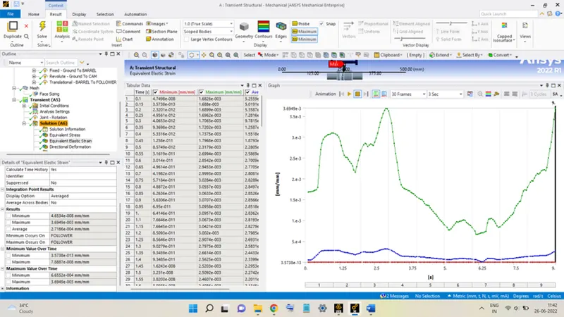
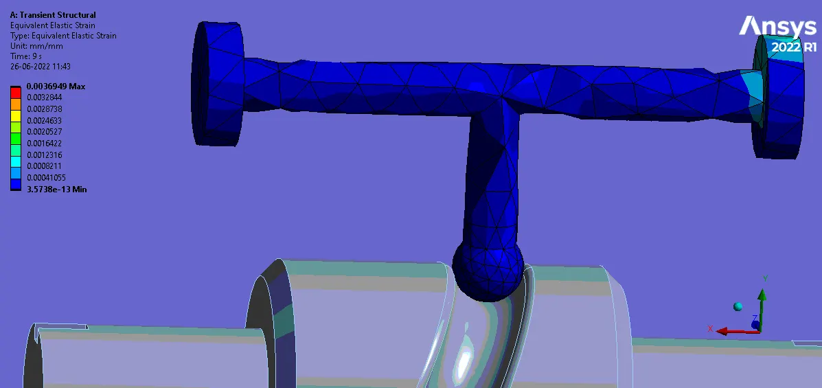
The strain developed in the FOLLOWER during the motion is shown in the figures above. Strain reaches a maximum value of 3.6949 x 10⁻³.
Deformation along Z-Axis:
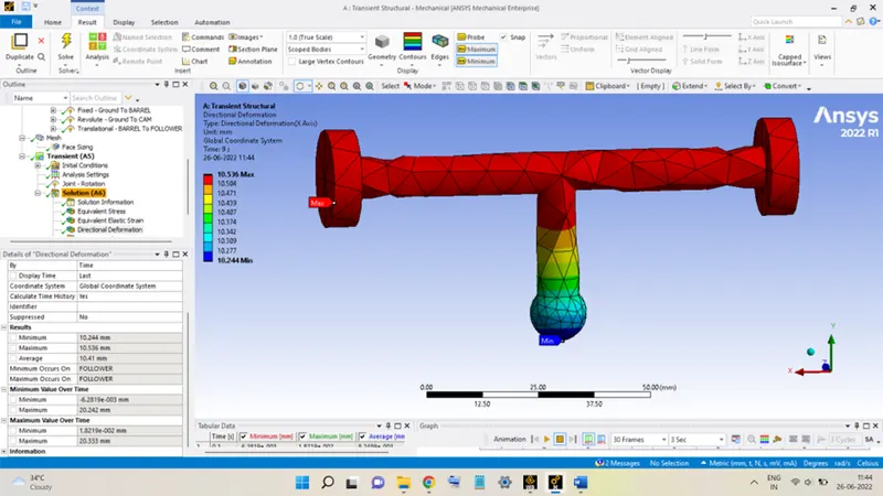
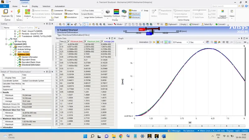
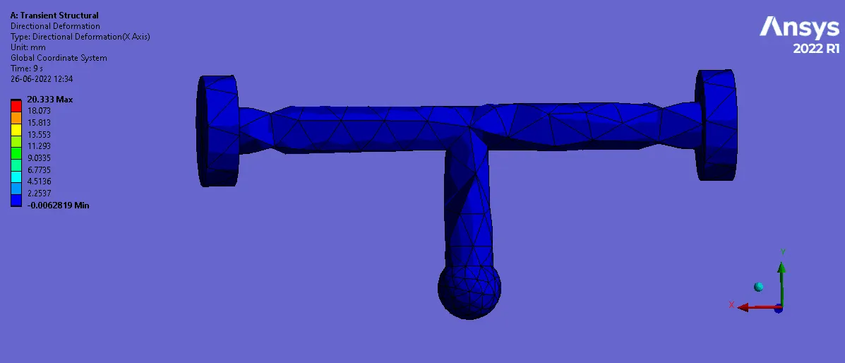
The deformation of the FOLLOWER during the motion is shown above. The maximum displacement of the FOLLOWER is seen to be equal to 20.333 mm.
Comparison:
|
TYPE OF JOINTS |
FRICTION COEFFICIENT |
MAX. EQUIVALENT STRESS (MPa) |
MAX. EQUIVALENT ELASTIC STRIAN |
MAX. DEFORMATION ALONG Z-AXIS (mm) |
|
FRICTIONLESS |
ZERO |
387.16 |
1.9461 x 10⁻³ |
20.315 |
|
FRICTIONAL |
0.1 |
529.91 |
2.6686 x 10⁻³ |
20.324 |
|
0.2 |
730.84 |
3.6949 x 10⁻³ |
20.333 |
The above table shows the results from all the different cases.
It is observed that as the Friction Coefficient value increases there is an increase in all the parameters. This has to be the case since friction always opposes the motion. Thus for the smooth functioning of the arrangement, it is necessary to keep the friction values as low as possible.