Week-7 Head Impact
Pedestrain Head Impact
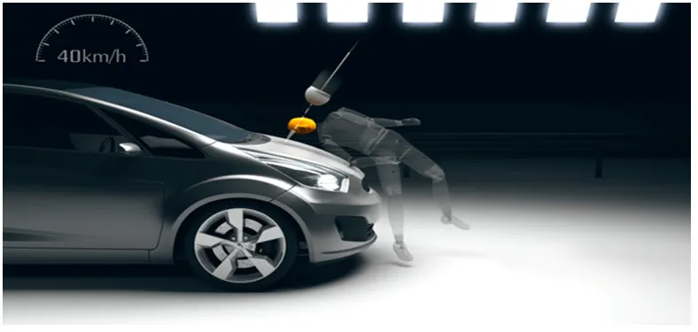
Pedestrian protection CAE is a part of vehicle safety engineering from a crash perspective. In pedestrian protection, we look for imparting minimum injury to head, upper leg (thigh), and lower leg (including knee) in case of an accident with a human subject. These tests are usually done at a lower velocity from 20-40 kmph as accidents tend to result in more severe circumstances above these velocities and braking in case of an accident often results in collision at low velocities.
ABSTRACT
Accident analysis shows that the head of the pedestrian impacts most frequently into or around the windscreen since cars in recent have a short hood. Therefore, the injury risks to the head in contact with various locations of the car including the windscreen and its frame were examined on the basis of headform impact tests. The HIC is high from contact with the cowl, lower windscreen frame or A pillar, and it is low with increasing distance from these structural elements. In the windscreen center, the HIC is less than 500.
INTRODUCTION
Since the body of the pedestrian impacts various locations of the car, sub-system tests using impactors are effective to evaluate the injury risk to each body region. The European Enhanced Vehicle-safety Committee (EEVC) proposed three sub-system tests: headformimpactor to bonnet top, legform to bumper, and upper legform to bonnet leading edge . The International Harmonized Research Activities (IHRA) Pedestrian Working Group and International Standard Organization (ISO/TC22/SC10/WG2) also presented similar sub-system tests. Head injuries pose a serious threat to life,andcomplete recovery is often not possible. In pedestrian-vehicle impact, the head is also the most frequent injured body region resulting in death . Thus, it is most important to evaluate injury risks to the head.
Euro NCAP pedestrianheadimpactPedestrian head Impact grid
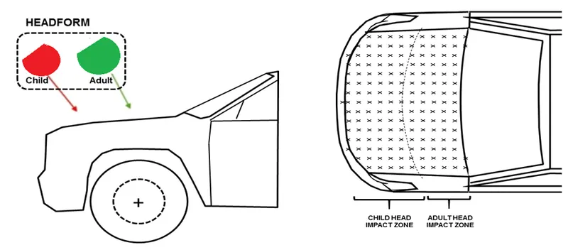
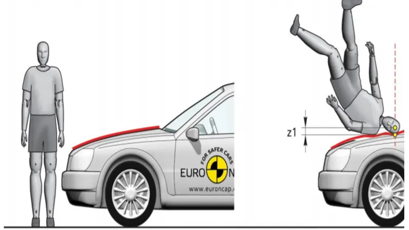
The head injury criterion (HIC) is a measure of the likelihood of head injury arising from an impact. The HIC can be used to assess safety related to vehicles, personal protective gear, and sport equipment.
Normally the variable is derived from the measurements of an accelerometer mounted at the center of mass of a crash test dummy’s head, when the dummy is exposed to crash forces.
It is defined as:
HIC = max(t1 or t2){(t2−t1)[1 / (t2−t11) ∫t1t2a(t)dt]^2.5}
SI = ∫T0 a(t) ^n dt
Where a(t) is head acceleration
T2-t1 is time interval
For example at HIC =650
90% probability of level 1
55% of level 2
20% of level 3
5% of level 4
Note: The unit system of mm ms kg kN
The small HIC value doen’t mean the head injury will be low level. Likewise a high level doesn’t mean a high level of injury,the real meaning is that, with higher the HIC valve the higher probability of getting high level head injury,
Abbreviated of injury scale
Level1: Slight damage to the brain with headache, dizziness, no loss of consciousness, confusion.
Level 2: Concussion with or without skull fracture, less than 15mins of unconsciousness , detached retina, face and nose fracture,
Level 3: Concussion with or without skull fracture for more than 15mins of unconsciousness without server neurological damage, multiple fracture, loss of vision ,multiple facial fracture, cervical fracture without damage to the spine.
Level 4: Multiple skull fracture withserver neurological damage.
Level 5: Concussion with or without skull fracture , more than 12hr of unconsciousness
Level 6: Death , critical factor with damage to the spine.
Procedure
Case 1: Simple head impact on the Rigid wall
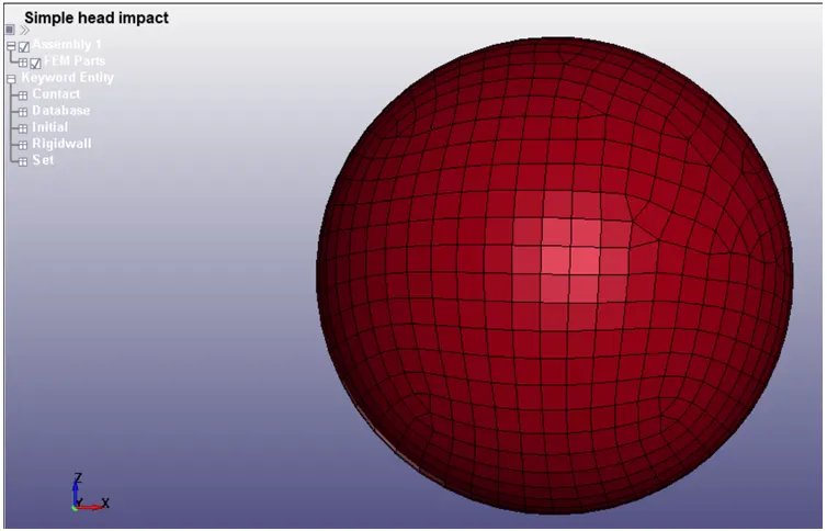
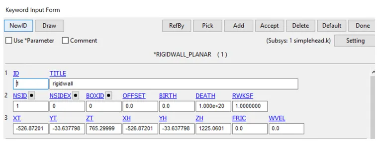
1.In Simple head geometry is import in the lsprepost , model has meshed as shell elements.In this case ,the simple head model is impact on the rigid wall .Create the rigidwall by using following steps create entity >Rigidwall>Planer>1N+NL>for Y direction.The rigid wall is created as 10mm from the bootom of model nodes.
2.Then section properties is created as*SECTION_SHELL_CARD.Keep thickness as 1mm is assigned for shell elements.

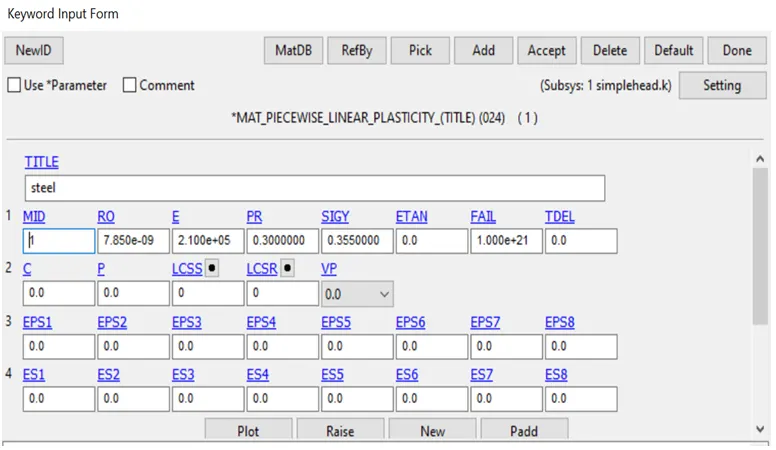
3.The material cards is used as MAT_24_Piecewise_Linear_Plasticity and assigned as steel properties
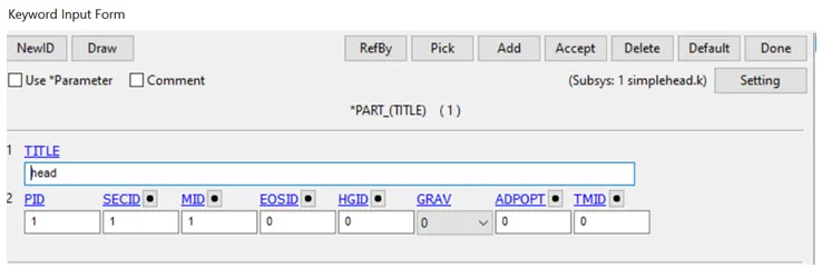
4.Part are created and assigned material and section property
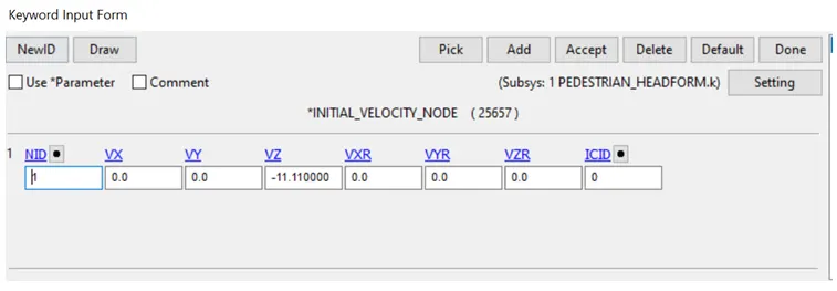
5.The geomentry is assumed to have 40kmph velocity along 50 degree along Y axis A node set is created for apply input velocity to the head impact model.Using *INITIAL_VELOCITY card, set an input velocity as 40Kmph (11.11mm/ms) is applied in the direction of rigid wall plane created.
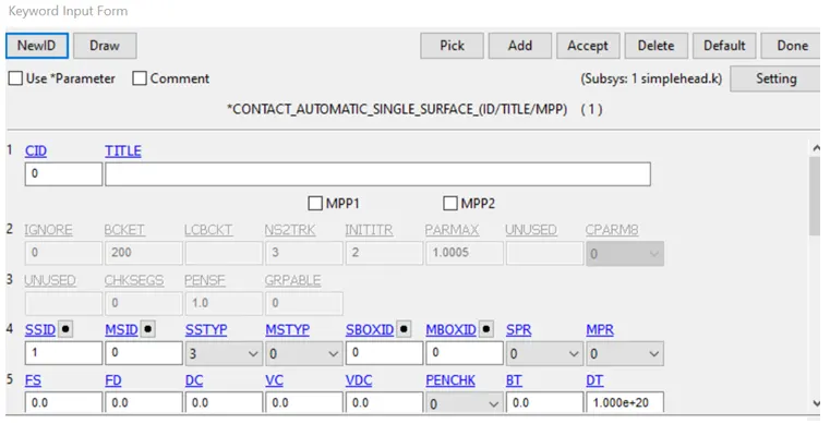
6.Self contact is created among the elements because during impact ,huge deformation will occur to over it we have create element of the parts as CONTACT_AUTOMATIC_SINGLE _SURFACE card is used .select all nodes as slaves.
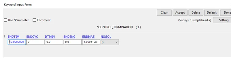
7.CONTROL_TERMINATION keyword is used to specfies the end time of the simulation as 10ms.
8.DATABASE keyword is created its specifies the output parameters that need to compulate during the simulation
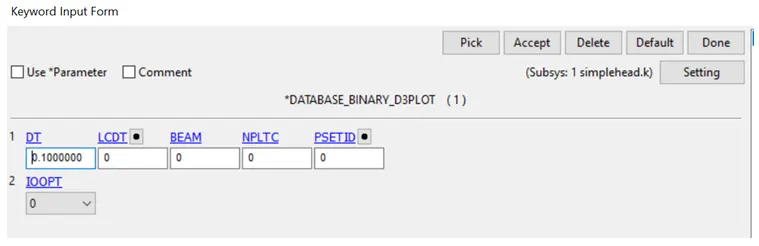
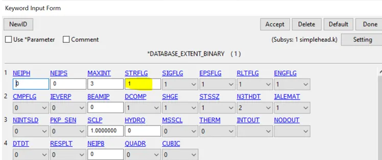
ASCII_output like GLSTAT is to calculates the energies distorated,NODOut for nodal displacements/acceleration, RWALL is rigid wall ,RWFORCE is rigid wall force .Animation 3d plot as 0.1ms.Binary extend strf as 1.
10.Save files is set to run in LS DYNA manager. A normal termination of the setup is achieved and result are plot in post processing.
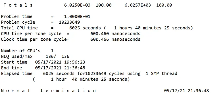
Animation results :
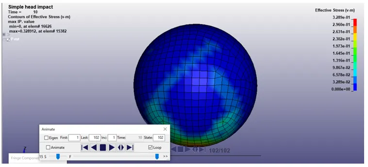
From the animation results we can visualize that how the simple head impact is behaving ,it just bouncing back after the deformation occurs max vonmises stress plots as 3.289e-01.
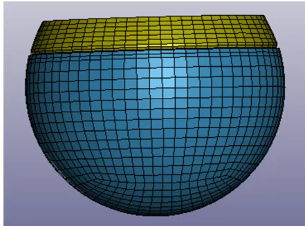
Case 2: Pedestrian headfoam model impacting on the rigid wall
The standard model of child headform is provided below
Follow the same procedure as simple head impact.After importing Pedestrianheadfoam model it involve to rotation of the part hence create a impact angle as 50 degree with the rigid wall ..
These can be done using *INCLUDE_TRANSFORM and *DEFINE_TRANSFORMATION keywords .
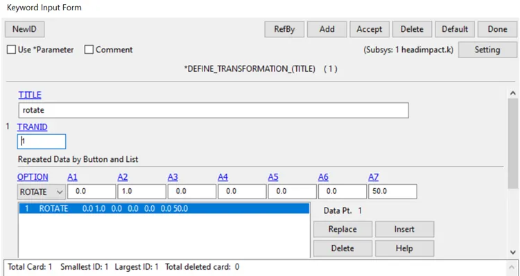
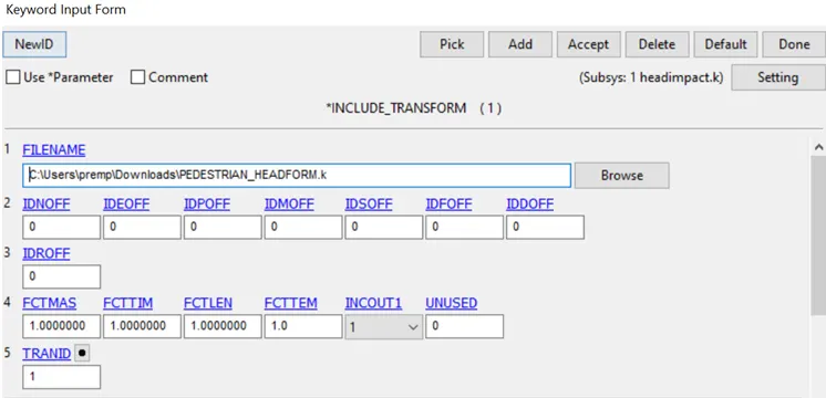
DEFINE_TRANSFORMATION
A transformation for the INCLUDE_TRANSFORM keyword option.The *DEFINE_TRANSFORMATION command must be defined before the *INCLUDE_TRANSFORM command can be used.
In these we are using Rotate through an angle (deg), a4. The axis
of rotation is defined by a vector going from the node with ID a1 to the node with ID a2 and passing through the node with ID a3 (a3 could be the same as a1 or a2). The three nodes must be defined before they are referenced. Only 1 ROTATE3NA option is permitted within a *DEFINE_TRANSFORMATION definition
(NOTE: When *DEFINE_TRANSFORMATION is called from within the target of an *INCLUDE_TRANSFORM keyword, the result will involve stacked transformations)
INCLUDE_TRANSFORM
This keyword is modified of include keyword ,it helps us the change and transform the imported model to creating viewport.
Procedure
1.Model is import in the lsprepost , model has meshed as shell elements.In this case ,the simple head model is impact on the rigid wall .Create the rigidwall by using following steps create entity >Rigidwall>Planer>1N+NL>for Y direction.The rigid wall is created as 10mm from the bootom of model nodes.
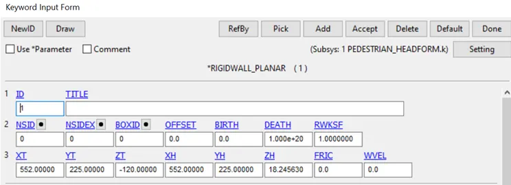
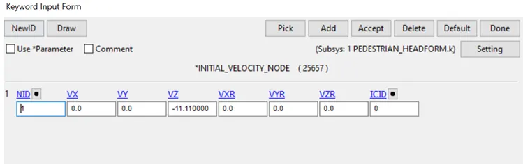
2.Thegeomentry is assumed to have 40kmph velocity along 50 degree along Y axis
- A node set is created for apply input velocity to the head impact model.Using *INITIAL_VELOCITY card, set an input velocity as 40Kmph (11.11mm/ms) is applied in the direction of rigid wall plane created.
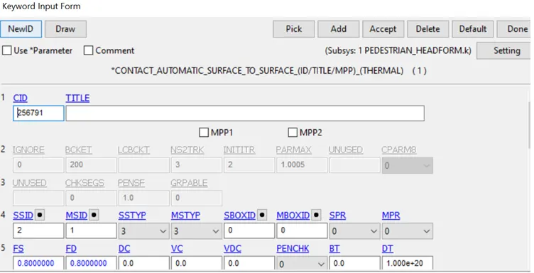
4.CONTACT_AUTOMATIC_SURFACE_TO_SURFACE card is established between the solid parts .
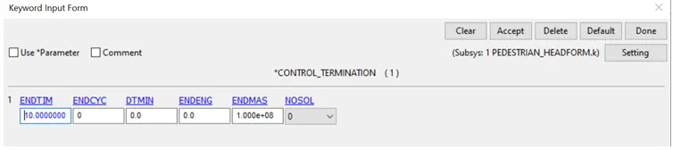
5.CONTROL_TERMINATION keyword is used to specfies the end time of the simulation as 10ms.
6.DATABASE keyword is created its specifies the output parameters that need to compulate during the simulation
ASCII_output like GLSTAT is to calculates the energies distorated,NODOut for nodal displacements/acceleration, RWALL is rigid wall ,RWFORCE is rigid wall force .Animation 3d plot as 0.1ms.Binary extend strf as 1.
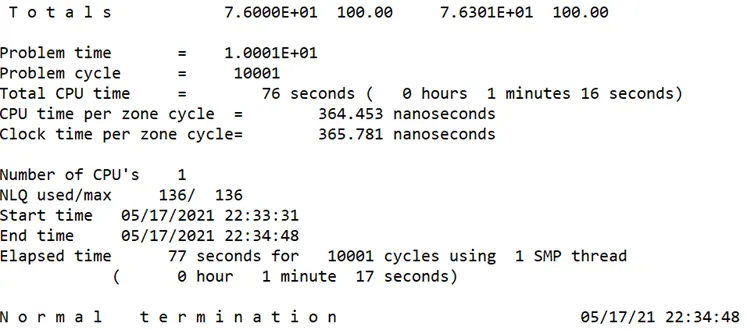
7.Save files is set to run in LS DYNA manager. A normal termination of the setup is achieved and result are plot in post processing.
Animation plots
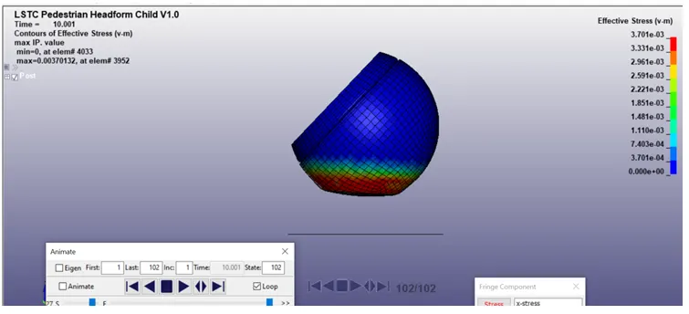
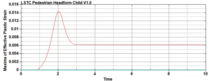
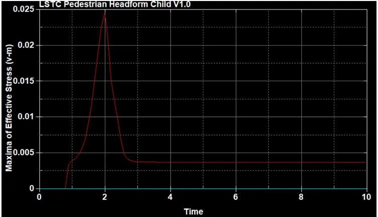
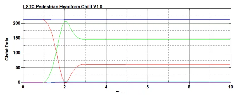
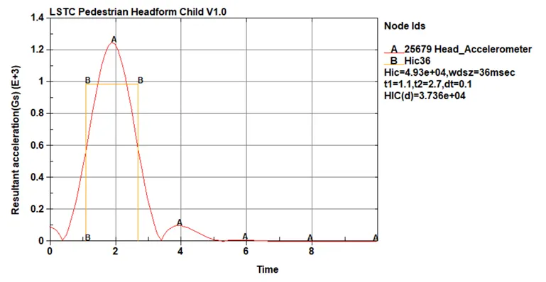
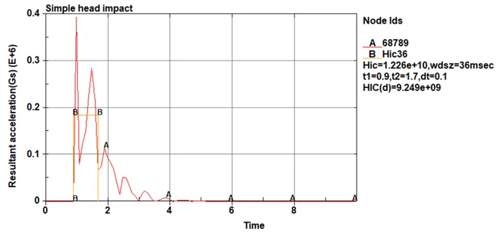
From the above plot, the HIC values for the pedestrain head impact on the rigid wall .The HIC36 valves obtained from the LS_PrePost is 4.93e+04 and HIC (d) value is 3.736e+04
Case3:Pedestrianheadfoam model impacting against rigid hood
The hood model ,FE model is opened in ldprepost using File>open>LS_Dyna keyword file
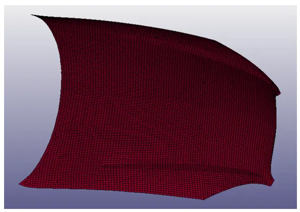
This case same simulation procedure but it will impact occurs on the meshed hood like real life pedestrian accidents
Import the meshed hood followed by pedestrian headfoam model at 45 degree towards the hood by using *(DEFINE_TRANSFORMATION and *INCLUDE_TRANSFORM
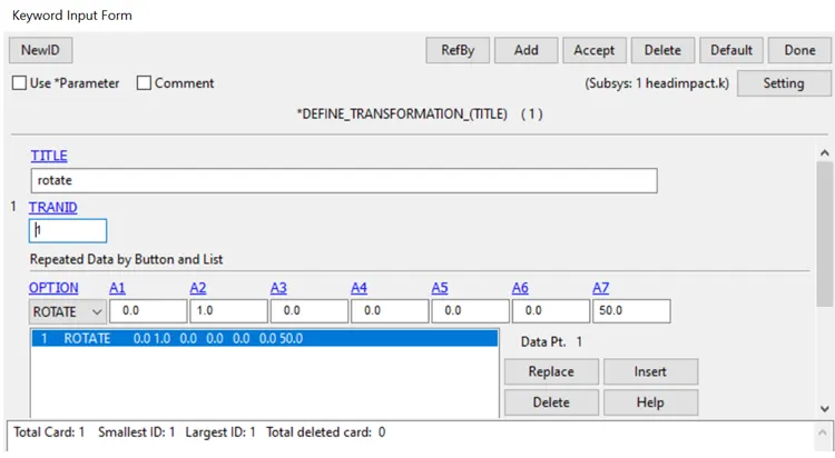
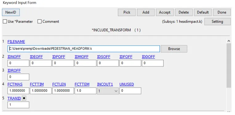
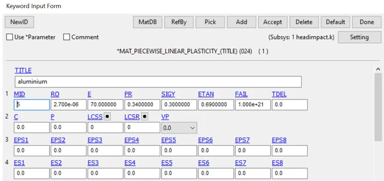
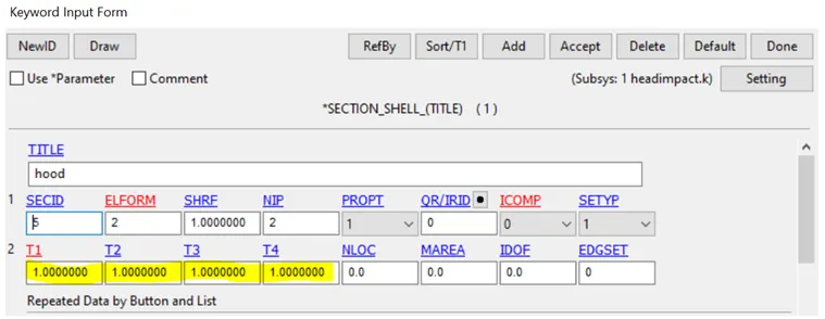
The hood is modeled as rigid material *MAT_20 with aluminium as material properties .section property as sheel element with thickness 1 mm
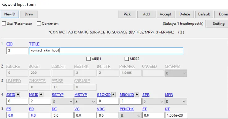
The CONTACT_AUTOMATIC_SURFACE_TO_SURFACE card is used to define contact between hood and child headform model .The skin as slave and hood as master
As per the EURO NCAP stdandard , the initial velocity is taken as 40KMPH, 11.11mm/ms at the angle 50 degree.as followed by previous cases
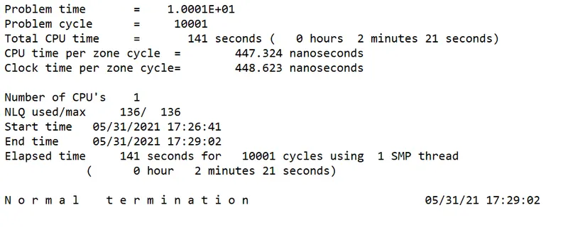
Save files is set to run in LS DYNA manager. A normal termination of the setup is achieved and result are plot in post processing
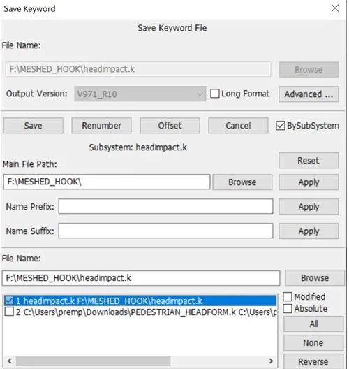
Save files is set to run in LS DYNA manager. A normal termination of the setup is achieved and result are plot in post processing
Animation plots :
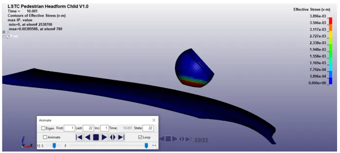
From the above plot, the HIC values for the head impact on the hood .The HIC36 valves obtained from the LS_PrePost is 25.09 and HIC (d) value is 185.3
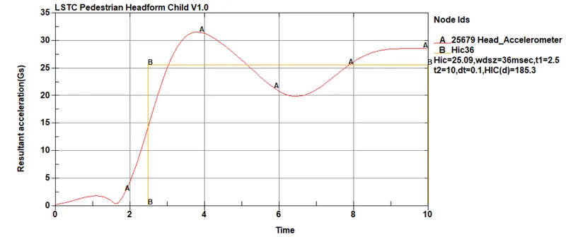
From the above plot, the HIC values for the head impact on the hood .The HIC36 valves obtained from the LS_PrePost is 3.342e+04 and HIC (d) value is 2.538e+04.
The HIC value recorded in Accelerometer is plotted from the graph,we can see the acceleration is increased and decreased.
HIC = 25.09 which is less than the standard HIC value 650.
The HIC average is calculated between time interval of 2min 21sec.
Conclusion:
The head impact simulation are performed by 3 relevant post processing results case such as
Case1: simplehead impact the rigidwall
Case2: Pedestrain head impact the rigidwall
Case3:Head impact the hood.
According to simple head impact the rigid wall ,the general setup ,first start with an basic model to perform analysis with random material properties to perform the analysis.
In Pedestrain head impact the rigid wall ,the impact with a rigid wall is severe and deforms the geometry. Higher plastic deformation is seen while head impact the rigid wall.The HIC valve formed was 4.93e+04
In the actual head impact on car hood .the hood is an deformed body with aluminum material properties deforms during impact.The effect is lesser with 650
https://drive.google.com/drive/u/1/my-drive