Week-7 Head Impact
Aim: To perform the Head Impact Simulation and calculate the Head Impact Criterion (HIC) value for the following cases.
KEYWORDS: HIC, Pedestrian, Hood, Include, AIS, etc.,
SOFTWARE: LS-Dyna
OBJECTIVE:
1) Simple head model impacting against a rigid wall (Case-1).
2) Child headform dummy model impacting against a rigid wall (Case-2).
3) Child headform dummy model impacting against the hood (Case-3).
INTRODUCTION:
Child Head Impact:
Car-pedestrian accidents account for a considerable number of automobile accidents in industrialized countries. Head injury continues to be more concerned with Automobile impacts. Because the head is the most seriously injured part in many collisions including in pedestrian automobile collisions. To reduce the severity of such injuries international safety committee has proposed subsystem tests in which headform impactors are impacted upon the car hood.
Currently in India, Automotive Indian Standard (AIS) 100, Amendment 1 is used to evaluate the performance of vehicles against pedestrian safety. This standard has been harmonized from the international evaluation standard Global Technical Regulation No. 9 (GTR 9), whose purpose is to bring about an improvement in the construction of the fronts of vehicles and, in particular, those areas which have been most frequently identified as causing injury when in collision with a pedestrian or other vulnerable road user. The tests required are focused on those elements of the child and adult body most frequently identified as sustaining an injury, i.e. the adult head and leg and the child's head. To achieve the required improvements in the construction of vehicles, the tests are designed in such a way that they will represent the rear world accident scenario.
Wrap Around Distance (WAD):
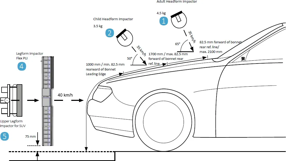
When a car crashes on the pedestrian, the whole human body wraps around the front shape of the car, and the head impacts on the bonnet or the windscreen. The distance at which the head impacts on the car from the ground is called the Wrap Around Distance (WAD). To be specific the Wrap Around Distance is a measurement of the distance from the ground to the head impact zone over the outer surface of the car. The wrap around distance is measured longitudinally in the center of the vehicle from the ground. The severity of the injury caused by the frontal crash depends on the type and shape of the vehicle, the speed of the vehicle, and the movement of the pedestrian relative to the vehicle. In addition to these parameters, the wrap-around distance plays a major role in the safety measures of a pedestrian.
During the crash analysis, based on the Wrap Around Distance(WAD), two test areas will be created namely the Child head impact zone and the Adult head impact zone. The child head impact zone is between 1000 to 1700 mm WAD and the adult head impact zone ranges between 1700 to 2100 mm WAD.
Head injury criteria (HIC):
The headform impactors are used to test the behavior of vehicle structures such as the hood. In a pedestrian-vehicle impact, the kinematics and severity of pedestrian injuries are affected by the impact locations on the vehicle and body velocities after impact. The objective of this project is to analyze the pedestrian kinematics in a Pedestrian-Car accident scenario and determine the Head Injury Criteria (HIC) from the head resultant acceleration, for head impacts on the vehicle hood
The equation used for the measurements of the head injury of the whole model for the pedestrian head impact was head injury criteria (HIC). It has been used to predict the risk of engine hood to a pedestrian during the collision
HIC is calculated according to the below Equation

Where
- a: the resultant acceleration (as a multiple of 10 ms-2 or about 1 g
- t1, t2: two-time instants (in seconds), which define the start and end of the recording when HIC is at maximum. Values of HIC at the time interval t1-t2
HIC(d)=0.75446(Free Motion Headform HIC)+166.4
At HIC=650,
90% probability of level one,
55% of level 2,
20% of level 3,
5% of level 4.
Abbreviated Injury Scale (AIS):
1) Slight damage to the brain with headache, dizziness, no loss of consciousness, confusion.
2) Concussion with or without skull fracture, less than 15 minutes of unconsciousness, detached retina, face, and nose fracture.
3) Concussion with or without skull fracture for more than 15 minutes of unconsciousness without severe neurological damage, multiple skull fractures, loss of vision, multiple facial fractures, cervical fracture without damage to the spine.
4) Multiple skull fractures with severe neurological damage.
Note: The unit system used is kg-mm-ms.
Procedure:
(I) Case-1 Simple head impacting against the rigid wall:
Importing the model:
1) The given LS-Dyna keyword file of the simple head FE model is opened in LS-PrePost using option File>Open>LS-Dyna Keyword File.
Section Creation:
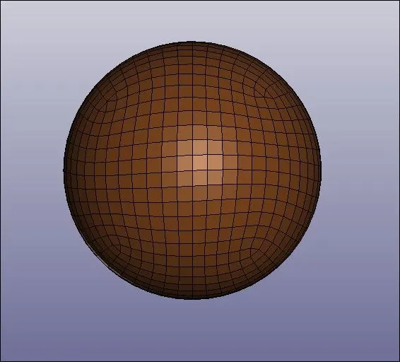
2) Since the Simple headform are meshed using the 2d elements we will define them with the SECTION_SHELL card.
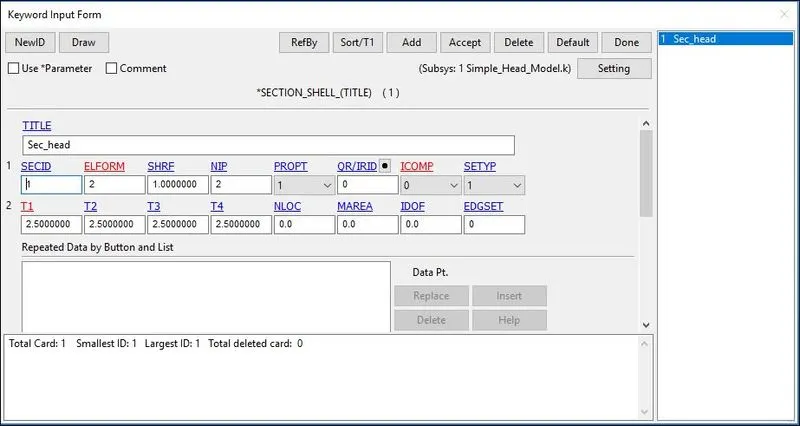
Here,
- SECID: Section ID. SECID is referenced on the *PART card. A unique Number or label must be specified.
- ELFORM: Element formulation options.= 2 Belytschko-Tsay (default).
- SHRF: Shear correction factor which scales the transverse shear stress.= 1
- NIP: Number of through-thickness integration points = 2
- T1: Shell thickness = 2.5mm
Material Creation:
3) We are supposed to define a material card for the Headform. We are using the MAT_ELASTIC card for headform.
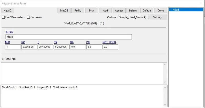
Here,
- MID: Material identification. A unique number or label not exceeding 8 characters must be specified.
- RO: Mass density.
- E: Young’s modulus. Reasonable values have to be chosen for contact analysis.
- PR: Poisson’s ratio. Reasonable values have to be chosen for contact analysis.
Assigning the Material and Section to their respective Part:
4) The material and section are assigned to their respective part ID’s.
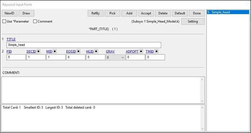
Boundary Conditions:
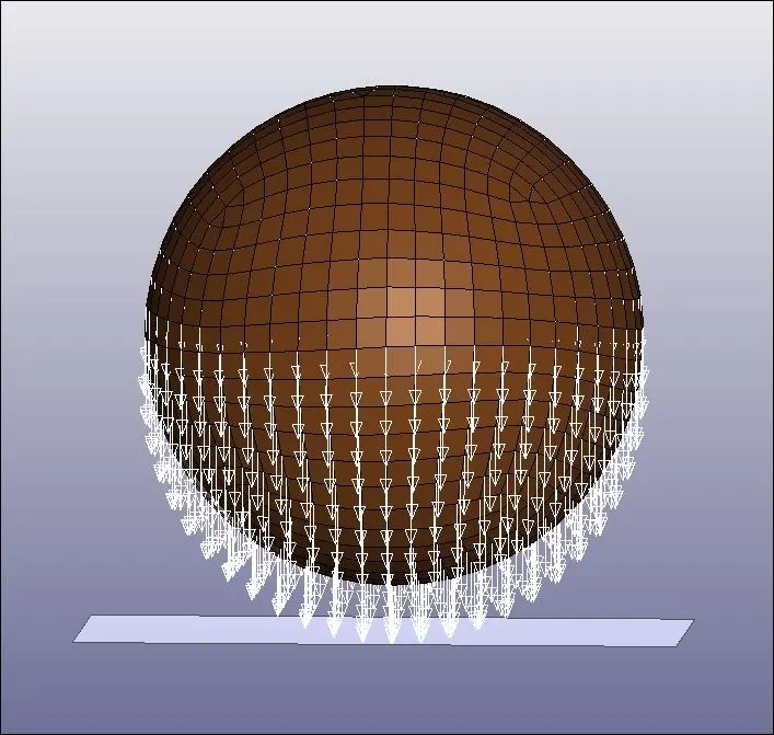
5) The rigid wall is created at a distance of 15 mm from the bottom of the simple head model.
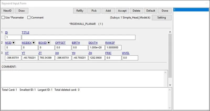
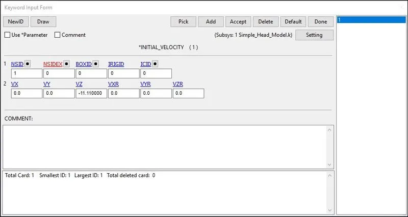
6) The simple head model is assumed to be impacting the rigid wall at a velocity of 40 kmph i.e. 11.11 mm/ms in negative Z-direction towards the rigid wall.
Here,
- NSID: Node Set ID, we already created the node-set for the floor.
- VX: Velocity along Translational X-axis.
- VY: Velocity along Translational Y-axis.
- VZ: Velocity along Translational Z-axis.
- VXR: Velocity along Rotational X-axis.
- VYR: Velocity along Rotational Y-axis.
- VZR: Velocity along Rotational Z-axis.
Contact Details:
7) The contact type selected is AUTOMATIC_SINGLE_SURFACE. It is quite helpful to apply this contact method in the crash models because all the elements are included in one single set and LS-DYNA considers also when a part comes into contact with itself. The FS and FD that are static and dynamic friction coefficients with a value of 0.02 are entered in the contact card. The simple headform model is the slave(SSID=5).
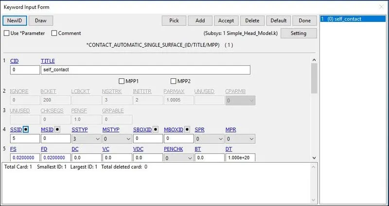
Here,
- SSID: Slave SetID, is defined using part type.
- MSID: Master SetID, is also defined using part type.
- SSTYP: Slave Set Type, it is selected according to the part.
- MSTYP: Master Set Type, it is also selected according to the part.
Control Cards:
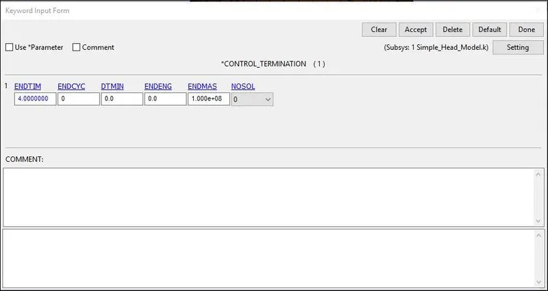
8) The Control_Termination function is enabled to specify the end time of the simulation. The termination time is set for 4 ms.
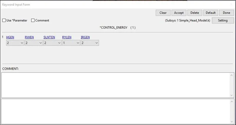
9) Control_Energy provides controls for energy dissipation options.
Here,
- HGEN: Hourglass energy calculation option. Is set to 2 In Which hourglass energy is computed and included in the energy balance.
- RWEN: Rigid wall energy dissipation option: Is set to 2 in Which energy dissipation is computed and included in the energy balance.
- SLNTEN: Sliding interface energy dissipation option Since the Contact is Defined it is set to 2 so that energy dissipation is computed and included in the energy balance.
Database Cards:
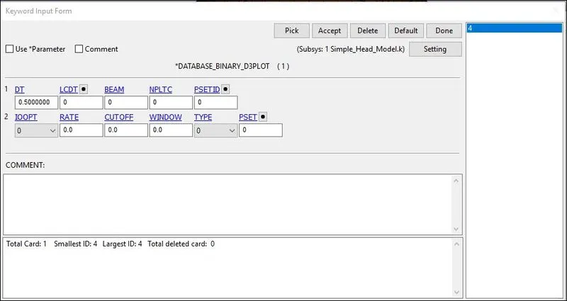
10) The time step value of 0.5 ms is given for the BINARY_D3PLOT and DATABASE_ASCII option for GLSAT, MATSUM, NODOUT, and RWFORC.
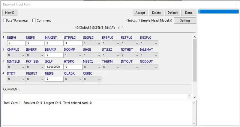
11) DATABASE_EXTENT_BINARY card with STRFLG =1, is used to compute the elastic strain in the model.
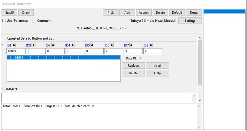
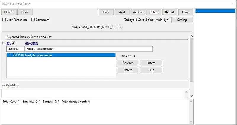
12) DATABASE_HISTORY_NODE card is used to compute the HIC value of a 688991 node in the model.
Keywords and Model Checker:
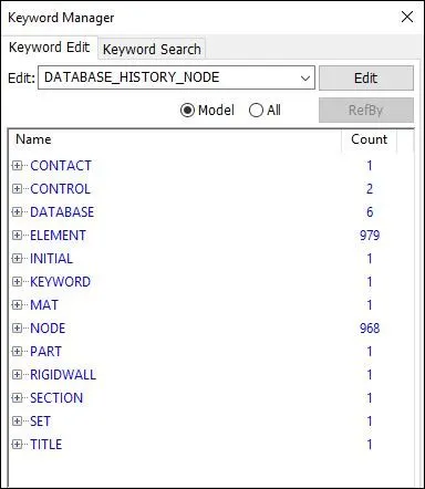
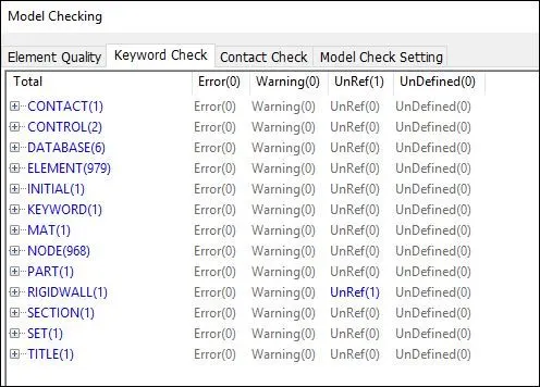
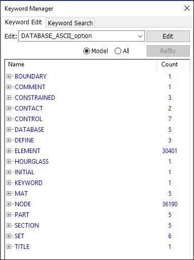
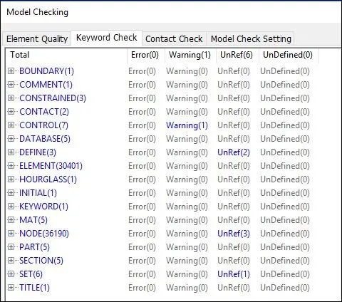
13) Finally, we have set up the simulation model and have a final look at our keyword manager which contains all the necessary parameters for running the simulation. Also, we perform model checking to find any errors or warnings present simulation model.
(II) Case-2 Child headform dummy model impacting against the rigid wall:
Importing the model:
1) The standard dummy model of child headform is provided with the necessary keyword for impact simulation.
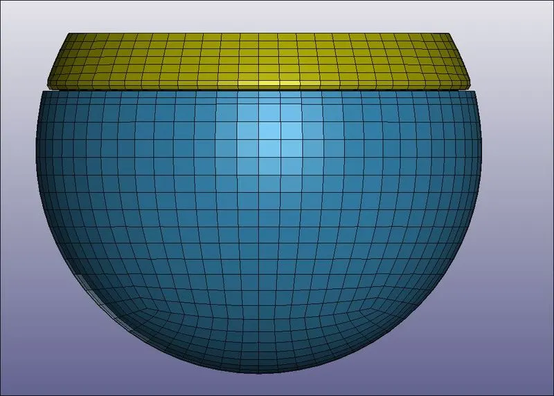
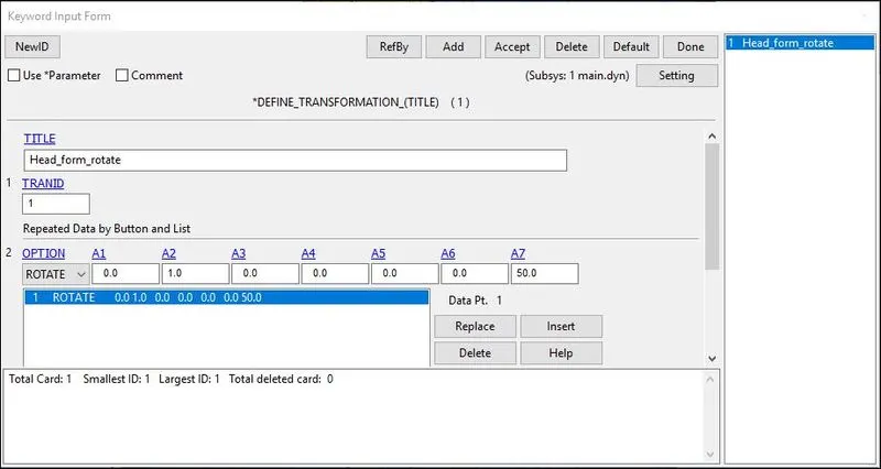
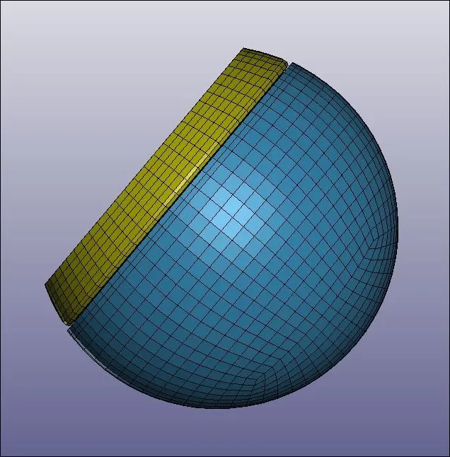
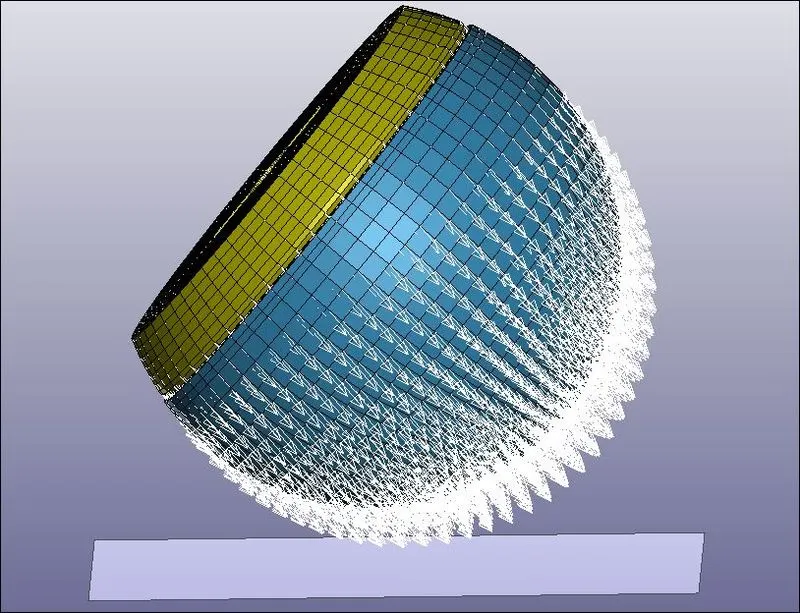
2) For case (2) impact simulation, the provide standard dummy model of child headform has to be rotated about 450 along the Y-axis to replicate the Euro NCAP impact simulation, by pulling it into a new keyword file created by LS-PrePost by using *DEFINE_TRANSFORMATION and *INCLUDE_TRANSFORM. Using the DEFINE_TRANSFORMATION card with TRANID=1, the dummy headform model is rotated by OPTION>ROTATE along Y-axis (A2=1) by 450 (A7=45).
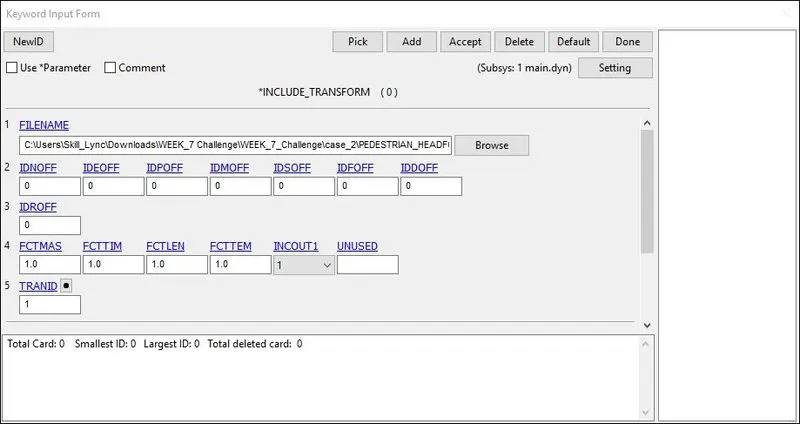
3) The INCLUDE_TRANSFORM card is used to pull the rotated standard dummy headform model file to the main file. The main file is saved with the ‘.dyn’ extension.
4) The main file is opened in LS-PrePost to add the necessary keywords to complete the simulation setup.
Boundary Conditions:
5) The rigid wall is created at a distance of 15 mm from the bottom of the simple head model.
6) As per Euro NCAP standards, the initial velocity is taken as 40 kmph i.e, 11.11 mm/ms at an angle 450. The vertical and horizontal components i.e. X-axis and Z-axis velocities are taken as -7.78 mm/ms and -7.78 mm/ms respectively.
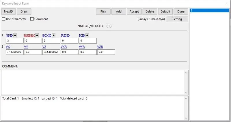
Here,
- NSID: Node Set ID, we already created the node-set for the floor.
- VX: Velocity along Translational X-axis.
- VY: Velocity along Translational Y-axis.
- VZ: Velocity along Translational Z-axis.
- VXR: Velocity along Rotational X-axis.
- VYR: Velocity along Rotational Y-axis.
- VZR: Velocity along Rotational Z-axis.
Control Cards:
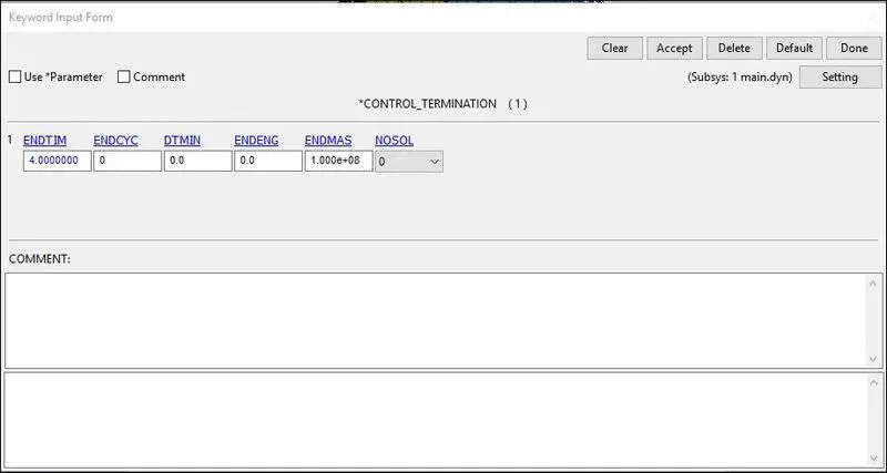
7) The Control_Termination function is enabled to specify the end time of the simulation. The termination time is set for 4 ms.
8) The Control Time step calculates the time step automatically for all the elements and uses the minimum value for the analysis
- TSSFAC (Scale factor for computed time step) = 0.9
- DT2MS(Time step size for mass scaled solutions) = - 0.0011000
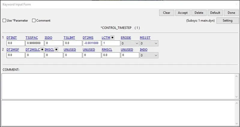
DT2MS - Negative: Mass is added to only those elements whose time step would otherwise be less than target time step size = (TSSFAC*|DT2MS|.)
Database Cards:
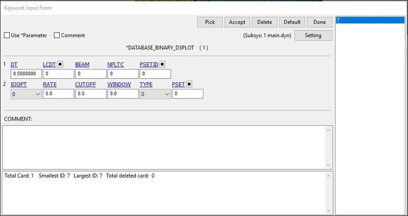
9) The time step value of 0.5 ms is given for the BINARY_D3PLOT and DATABASE_ASCII option for GLSAT, MATSUM, NODOUT, RCFORC, and RWFORC.
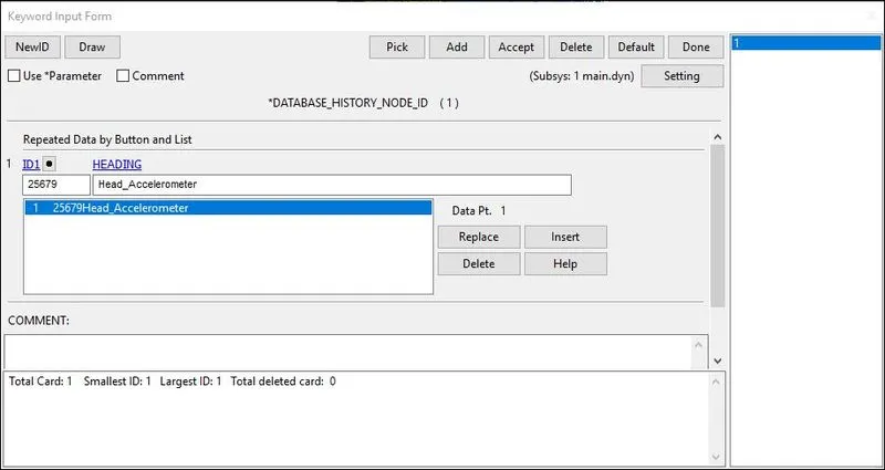
10) DATABASE_HISTORY_NODE card is used to compute the HIC value of a 25679 node in the model.
Keywords and Model Checker:
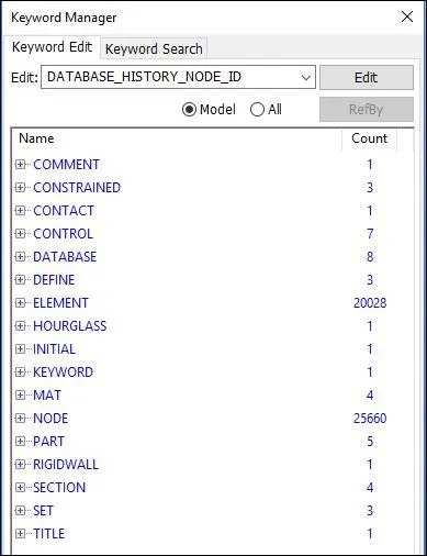
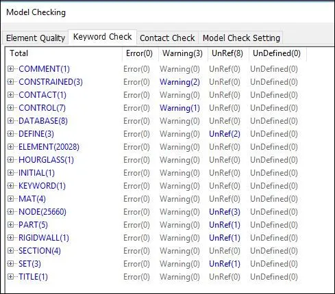
11) Finally, we have set up the simulation model and have a final look at our keyword manager which contains all the necessary parameters for running the simulation. Also, we perform model checking to find any errors or warnings present simulation model.
(III) Case-3 Child headform dummy model impacting against the hood:
Importing the model:
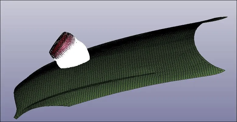
1) The hood model i.e. the FE model is opened in LS-PrePost using option File>Open>LS-Dyna Keyword File.
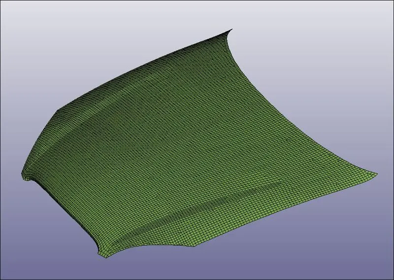
2) The keyword file of the hood is saved using the ‘.dyn’ extension. The keyword file of the hood is pulled into the main file using keywords *INCLUDE. The child headform is pulled into the main file by using keywords *DEFINE_TRASFORMATION and *INCLUDE_TRANSFORM which is similar to the case (2) scenario.
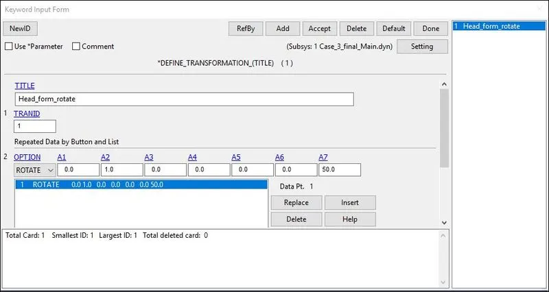
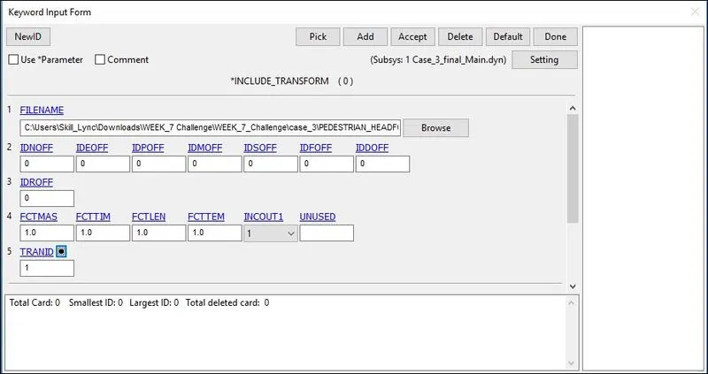
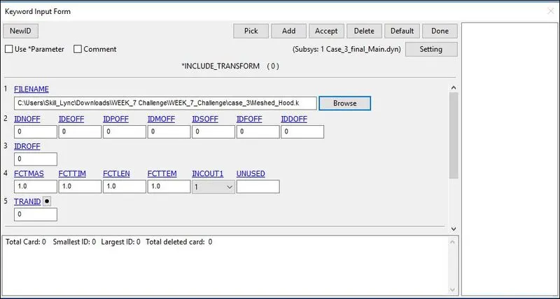
3) The main keyword file is opened in LS-PrePost to add necessary keywords to complete the impact simulation setup.
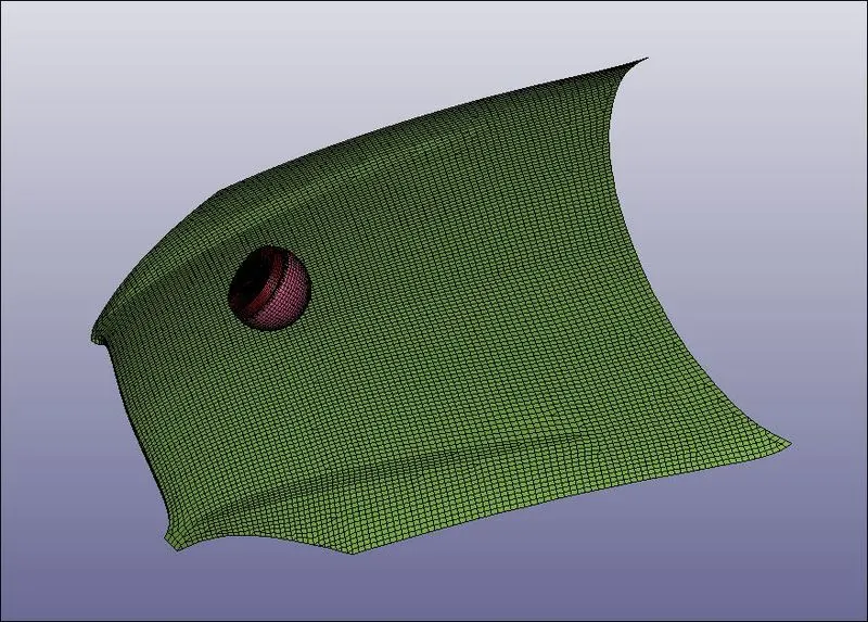
Section creation for Hood:
4) The section properties of the hood are assigned as shell elements with 2 mm thickness.
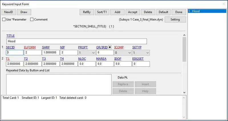
Here,
- SECID: Section ID. SECID is referenced on the *PART card. A unique Number or label must be specified.
- ELFORM: Element formulation options.= 2 Belytschko-Tsay (default).
- SHRF: Shear correction factor which scales the transverse shear stress.= 1
- NIP: Number of through-thickness integration points = 2
- T1: Shell thickness = 2 mm
Material Creation for Hood:
5) The MAT24 (Piecewise linear plasticity) material card is used to assign the Aluminium material properties to the hood. The MAT24 represents Piecewise linear isotropic plasticity. With this material model, it is possible to consider the effect of the strain rate.
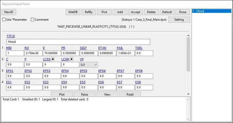
Here,
- MID: Material identification. A unique number or label not exceeding 8 characters must be specified.
- RO: Mass density.
- E: Young’s modulus. Reasonable values have to be chosen for contact analysis.
- PR: Poisson’s ratio. Reasonable values have to be chosen for contact analysis.
- SIGY: Yield Stress.
- ETAN: Tangent Modulus.
Assigning Section and Material of Hood to its Part:
6) The material and section are assigned to their respective part ID’s.
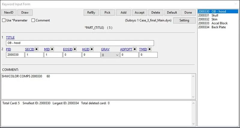
Boundary Conditions:
7) As per Euro NCAP standards, the initial velocity is taken as 40 kmph i.e, 11.11 mm/ms at an angle 450. The vertical and horizontal components i.e. X-axis and Z-axis velocities are taken as -7.78 mm/ms and -7.78 mm/ms respectively.
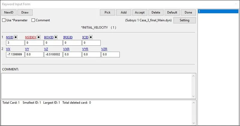
Here,
- NSID: Node Set ID, we already created the node-set for the floor.
- VX: Velocity along Translational X-axis.
- VY: Velocity along Translational Y-axis.
- VZ: Velocity along Translational Z-axis.
- VXR: Velocity along Rotational X-axis.
- VYR: Velocity along Rotational Y-axis.
- VZR: Velocity along Rotational Z-axis.
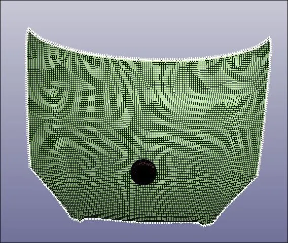
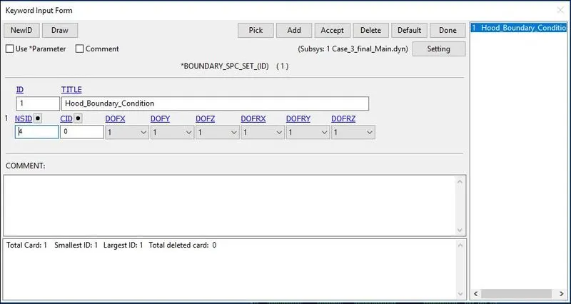
8) Using create entity option the nodes on the outer edges of the hood are selected and constrained all the translational and rotational motion using the option Boundary_SPC_Set.
Contact Card:
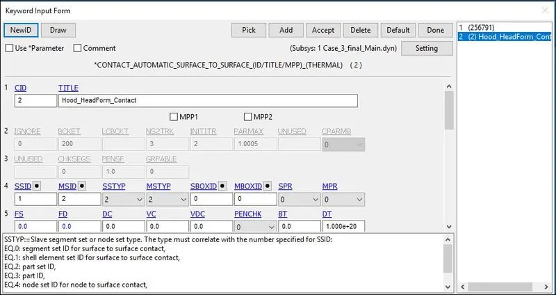
9) The CONTACT_AUTOMATIC_SURFACE_TO_SURFACE card is used to define contact between hood and dummy child headform model. The child headform model is taken as a slave and hood as a master.
Control Cards:
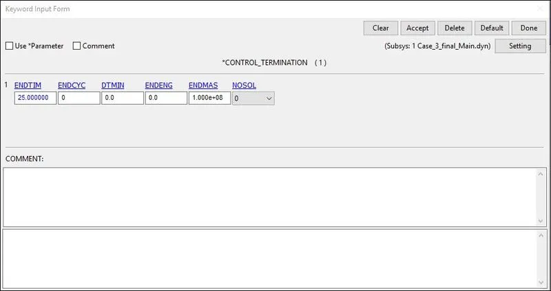
10) The Control_Termination function is enabled to specify the end time of the simulation. The termination time is set for 10 ms.
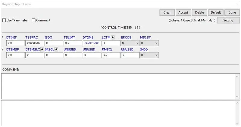
11) The Control Time step calculates the time step automatically for all the elements and uses the minimum value for the analysis
- TSSFAC (Scale factor for computed time step) = 0.9
- DT2MS(Time step size for mass scaled solutions) = - 0.0011000
Database Creation:
12) The time step value of 0.5 ms is given for the BINARY_D3PLOT and DATABASE_ASCII options for GLSAT, MATSUM, and NODOUT.
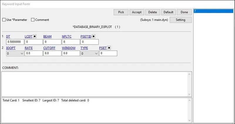
13) The DATABASE_HISTORY_NODE card is used to compute the HIC value of a 25679 node in the model.
 +
+
Keywords and Model Checker:
14) Finally, we have set up the simulation model and have a final look at our keyword manager which contains all the necessary parameters for running the simulation. Also, we perform model checking to find any errors or warnings present simulation model.
REULTS & DISCUSSION:
The D3plot output file is opened in LS-PrePost using option File>open>LS-Dyna binary plot.
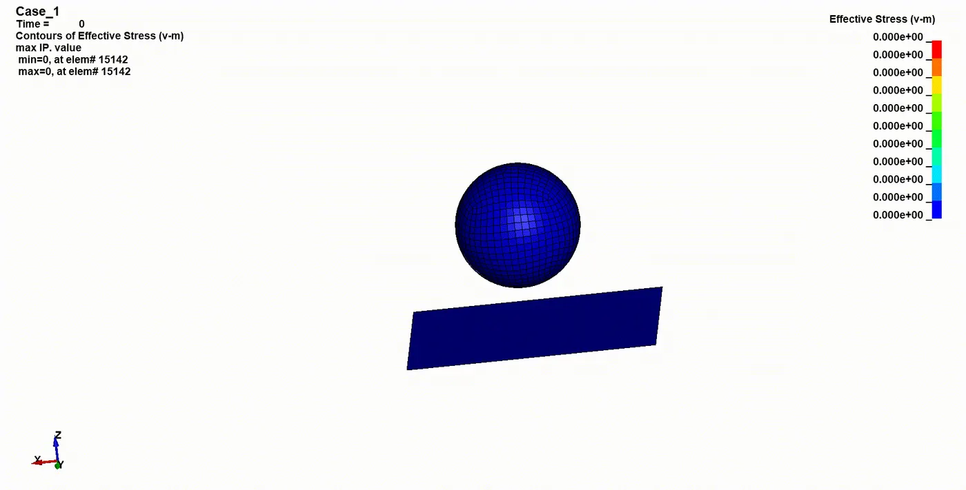
CONTOUR PLOTS OF VON MISES STRESS:
Case-1
Case-2:
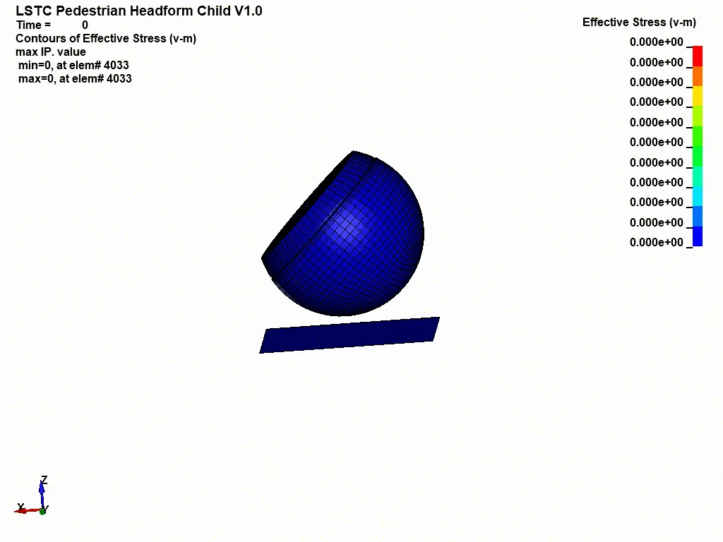
Case-3:
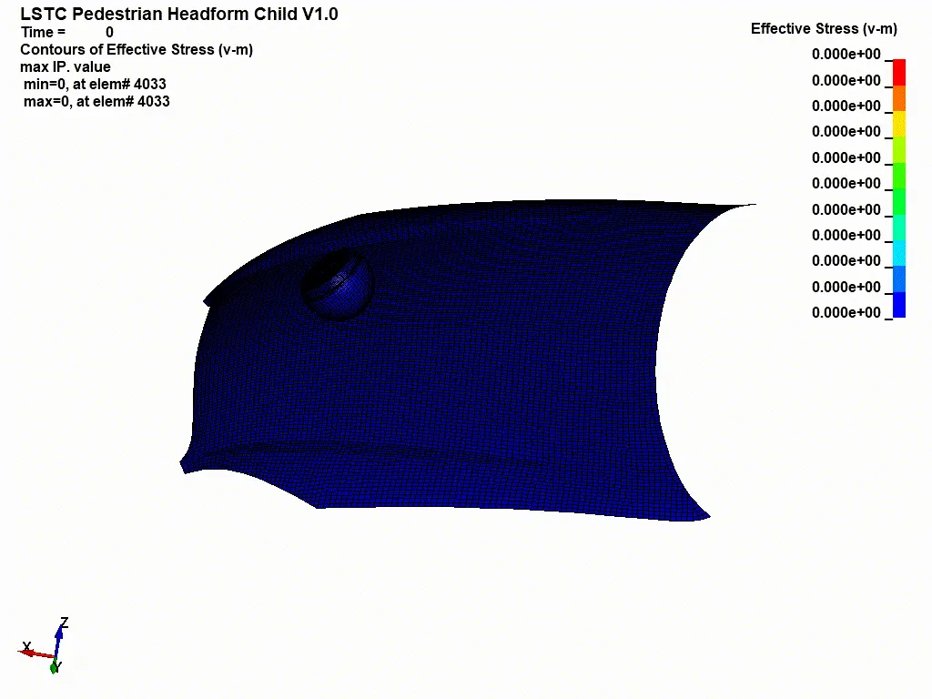
The stress values are higher at the instant of impact and reduce with fluctuations after the impact as the material is purely elastic. There is no significant deformation in the simple head geometry. The Case-2 animation and Plot depicts stress behavior in headform geometry after the impact. The material properties for this geometry are pre-defined and different from the simple head so, it shows different behavior. There is significant deformation in the geometry after the impact. The Case-3 animation and Plot show that the hood deforms after the impact and there is less deformation in the head compared to the second case. This is because of the elastoplastic material which has been defined to the hood, this material tends to deform elastically till the yield point and then deforms plastically after that.
CONTOUR PLOTS OF EFFECTIVE PLASTIC STRAIN:
Case-1:
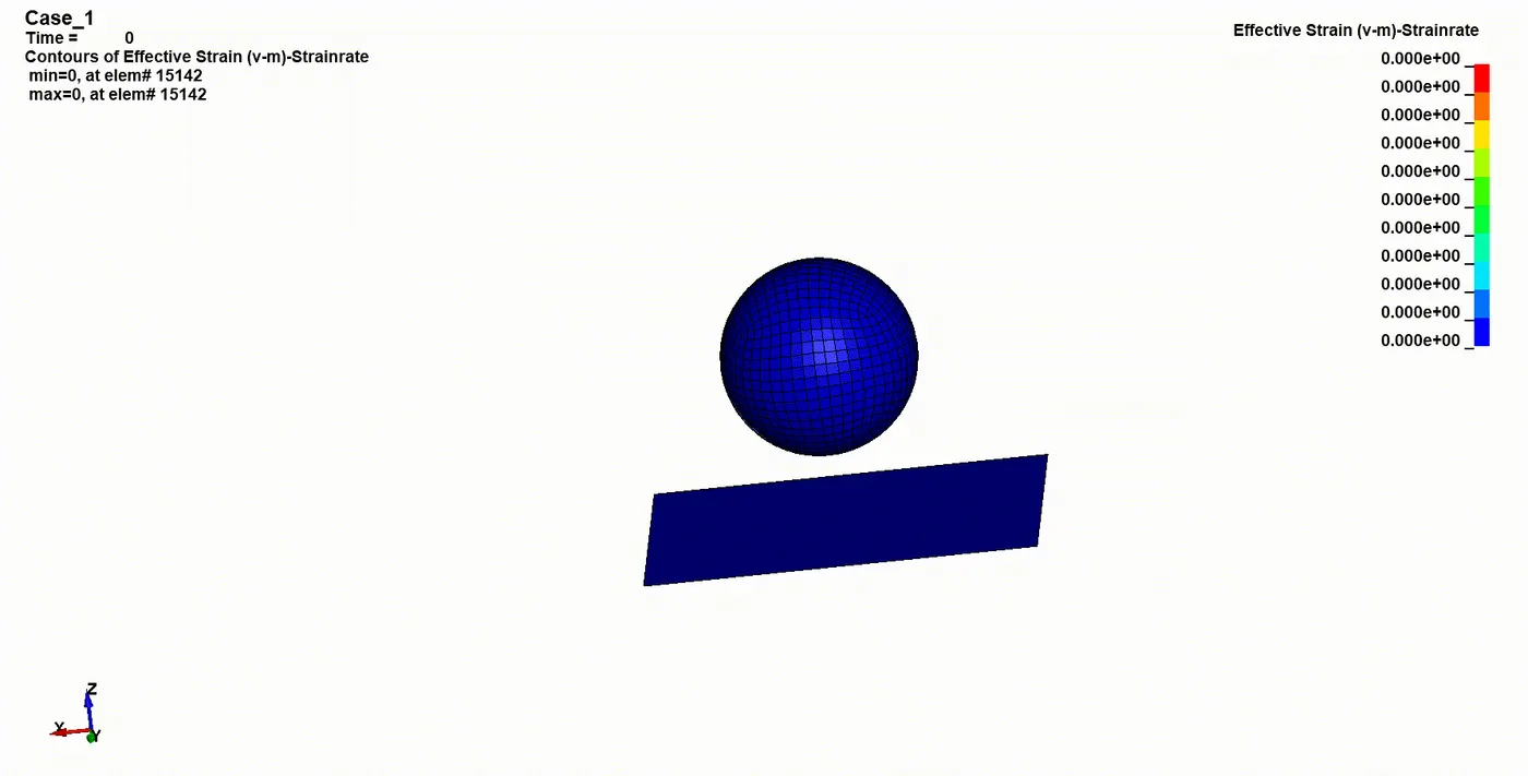
The total strain for simple head impact on a rigid wall is zero throughout as shown in the above plot. This is because of the high young’s modulus assigned to the simple head geometry (207GPa). This was a trial case and hence the material parameters were chosen randomly. It is also visible from the animation that there is no deformation of simple head geometry after the impact this relates to the very low strain values.
Case-2:
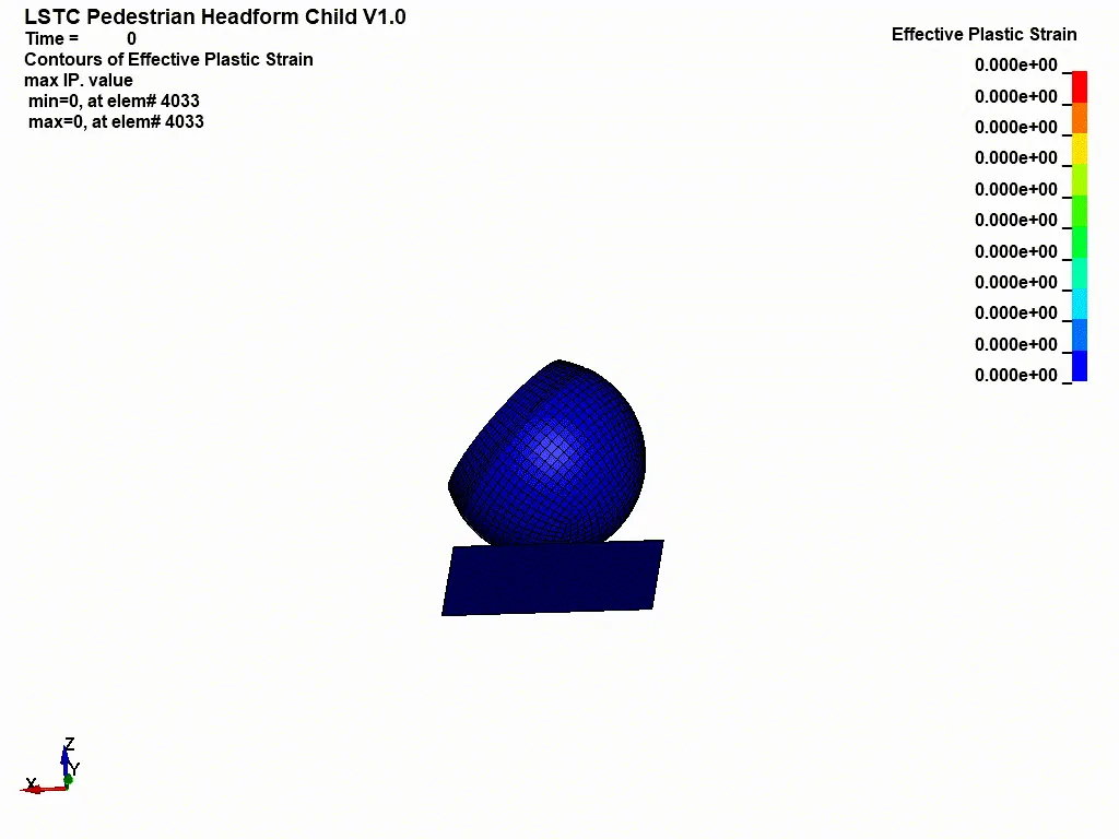
The Animation and Plot depict the total strain in headform geometry before and after the impact. Here the headform has been designed to replicate the child’s head. So this has similar properties that resemble an actual head. On the other hand, it is hit by a rigid wall which is basically a non-deformable body. So, it can be seen that after the impact the strain value increases (plastic + elastic), and the drop in strain value after 3.5 ms is due to the recovery of elastic strain. After the impact, the headform bounces back and we can see the elastic strain recovers fully but the plastic strain remains as a permanent deformation till the end. This same element is used to calculate the strain for the next case.
Case-3:
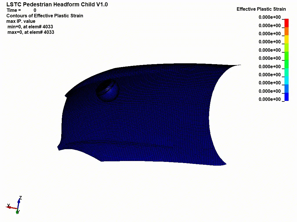
The above Animation and Plot show the total strain of headform impact with a hood. In this case, the hood is assigned with aluminum properties. So, it can deform and is not undeformable like a rigid wall. The headform geometry is the same as case 2 with material properties resembling the child’s head. From the animation, we can see the total strain increases gradually during impact. During impact, the hood deforms significantly and hence this reduces the impact on the headform relatively. We can get a rough picture that there is not much deformation in the headform compared to case 2. The plot shows fewer strain values compared to the case-2 plot this justifies the above explanation.
HIC Value and Plots:
HIC value is generally derived from the accelerometer mounted at the center of mass of the crash test dummy.
Case-1:
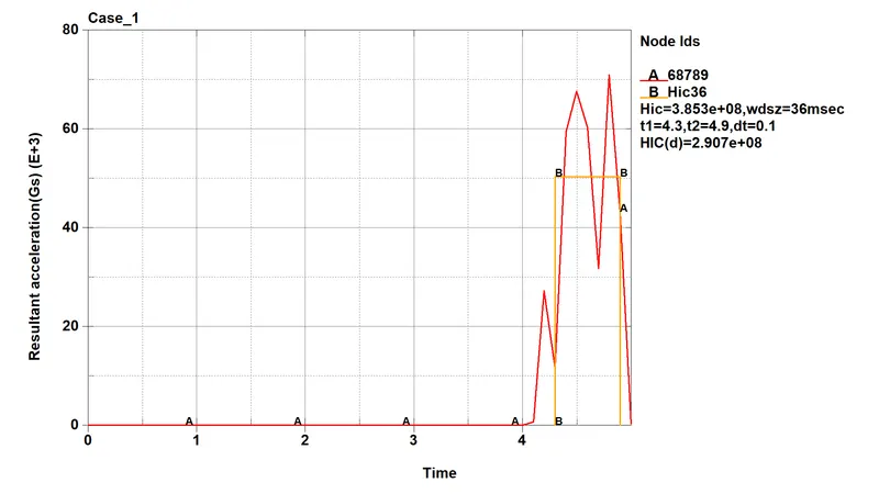
For the simple head impact test, a node on the outer surface was manually selected for result extraction. HIC-36 value is calculated in LS-PrePost and is basically measured for a time interval less than 36ms duration. From the above image, it can be seen that the HIC-36 value for simple head impact is 3.853E+08.
Manual calculation of HIC value for Case-1:
The expression to calculate HIC value is,
From the plot,
The average value of acceleration for the time interval of t1=4.4 ms and t2=4.9 ms,
So, the average acceleration from the graph is taken as around 50e3.
HIC = [50e3] ^ 2.5 * (4.4-4.9) * e-3
HIC = 2.795E+08
Case-2:
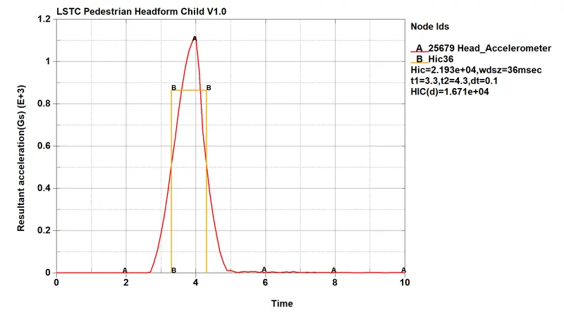
The HIC-36 value for headform impact is measured from an accelerometer place in the geometry. From both cases it can be seen, the resultant acceleration is increased and then decreased after the impact because the body comes to halt and again bounces back. The HIC-36 value for headform impact on the rigid wall is 2.193e+04.
Manual calculation of HIC value for Case-2:
The expression to calculate HIC value is,
From the plot,
The average value of acceleration for the time interval of t1=3.2 ms and t2=4.2 ms,
So, the average acceleration from the graph is taken as around 850.
HIC = [850] ^ 2.5 * (4.2-3.2) * e-3
HIC = 2.106E+04
Case-3:
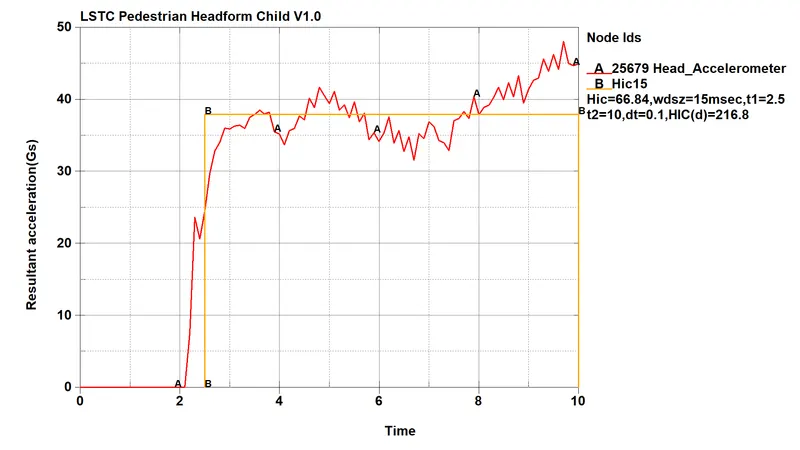
The above Plot shows the HIC-36 value for head and hood impact. If the time interval used to calculate the HIC value is shorter than 15ms, both HIC15 and HIC36 have the same value. If the time interval is larger than 15ms then HIC36 is higher. The HIC-36 value for headform impact on the hood is 66.84.
Manual calculation of HIC value for Case-3:
The expression to calculate HIC value is,
From the plot,
The average value of acceleration for the time interval of t1=2.5 ms and t2=10 ms,
So, the average acceleration from the graph is taken as around 38.
HIC = [38] ^ 2.5 * (10-2.5) * e-3
HIC = 66.76
CONCLUSION:
1. The head impact simulation is performed with all relevant post-processing results.
2. The simple head-model was defined with MAT_ELASTIC material card which implies the material is pure elastic that’s why the max stress is only there in the time of the impact there is no significant deformation in the simple head geometry. That’s why the HIC values are too high.
3. The standard model of the child head foam with proper material was used, Since the rigid wall is undeformable so the total stress is transferred to the head and deforms the headform geometry severely the HIC values are lower than case 1.
4. In this, the Headform impacts the car hood to study the real-life situation. The hood was defined with a piecewise linear plastic MAT_024 material model and with Aluminium as the material which is a deformable model so during the impact the hood deforms significantly and reduces stress and strain on the head foam and thus reduces HIC values and the value are lower than case 2.
5. HIC value is compared by Simulation and theoretically.