Week-7 Head Impact
HEAD IMPACT SIMULATION
INTRODUCTION:
Pedestrian safety and protection analysis is part of a Crash analysis performed in automotive industries. In this Vehicle safety engineering field, the engineers are required to design the automobile especially the front half i.e the bonnet and car hood in such a way that under circumstances that involve an accident or collision with pedestrians the vehicle has to impart less damage to the civilian as much as possible.
While it is proven from studies that during collisions with pedestrians the major injury is imparted on the head region with minor injuries on the torso and thigh region. Crash safety engineers consider the head which is more prone to injury that could lead to concussions or even death to be their main priority during crash analysis. These analysis results are also used by insurance companies.
The factor that is used by engineers to determine the level of damage imparted onto the head region is determined using theHIC factor which stands for Head Injury Criterion / Coefficient.
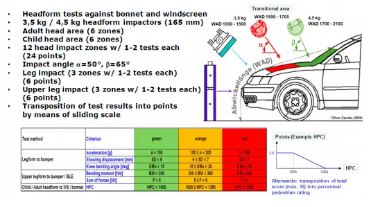
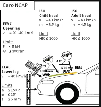
Tests that are generally done are shown below
OBJECTIVE:
To perform a head impact simulation and calculate HIC value.
the simulation is done with three different models and its results are to be compared.
- Impact simulation of a simple head impact with the Rigid wall.
- The impact simulation of the Headform provided with the Rigid wall.
- The impact simulation of the head form with the Hood.
CASE 1: SIMPLE HEAD MODEL AGAINST RIGIDWALL
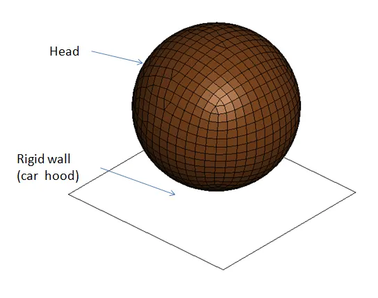
Normally we use standard dummy models provided by various specialized companies, but here we are going to create a simple sphere representing the head of the pedestrian and compare it with the dummy model.
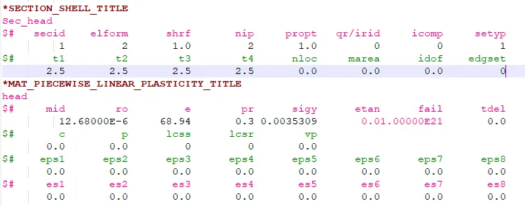
- Create a *SECTION_SHELL and a *MAT_24_PIECEWISE_LINEAR_PLASTICITY with a shell element formulation 2 and shell thickness of 5 mm.
- A RIGIDWALL_PLANAR is created from the CreEnt -> Rigidwall -> Planar Option normal to the z-axis and about a distance of 10 mm from the bottom node of the shell element.
- SET_NODES are created containing every node of the headshell part and an INITIAL_VELOCITY card containing the velocity rate of 40kmph which is about 11.11 mm/ms and along a direction of -ve Z-axis towards the rigid wall. NOTE: Since our head part consists of a sphere, rotation about an axis will not be used. However, in the case of real head-form dummy geometry, the pedestrian head will be aligned so as the front part (face) is set for an impact angle of about 35 to 75 degrees.
- During impact, if huge deformation occurs it could potentially lead to contact of elements with the adjacent elements in the same shell component. Hence, to impart a self-contact among each element of the part aCONTACT_AUTOMATIC_SINGLE_SURFACE card is used. The only parameter that needs to be initialized in this keyword is the slave set ID, which in our case will be the entire shell part.
- A *CONTROL_TERMINATION keyword is specified to initialize the end time of the simulation which is about 20 ms.
- In addition, the CONTROL_ENERGY card is also initialized to compute the hourglass and stonewall (rigid wall) energies during the analysis.
- Finally, the DATABASE keyword is created specifying the output parameters that need to be computed during the simulation including the animation d3plot with a time interval of 0.5 ms and ASCII_Outputs like GLSTAT- to calculate energies, NODOUT- for nodal displacement/acceleration and HIC value, and the RWFORCE - rigid wall force. The required nodes from which the results need to be extracted are specified in a SET_NODES and reference in a*DATABASE_HISTORY_NODE_SET card.
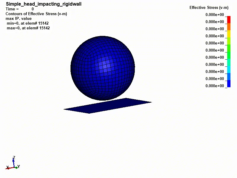
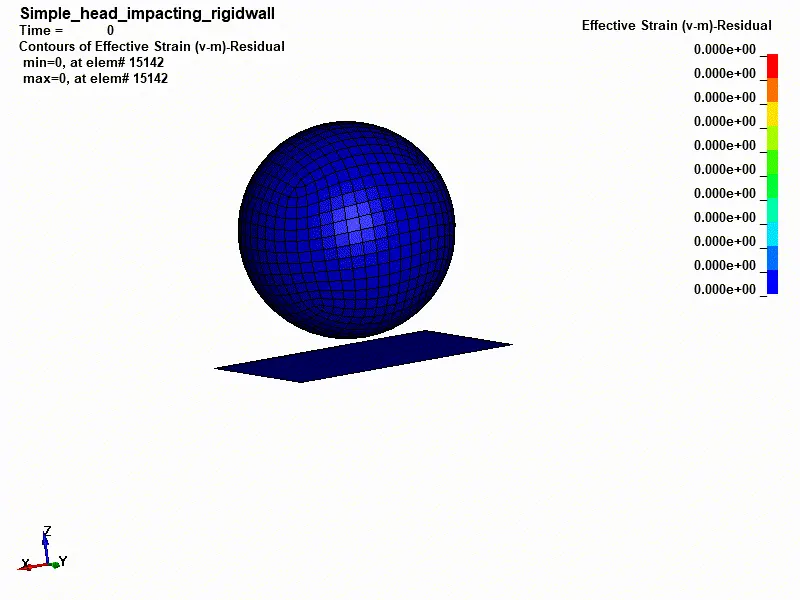
- After submitting the simulation, the post-processing is done. While the ASCII_Output parameters will be clearly analyzed for the real head model, the Von-mises stress experienced by the bodies during impact is shown below,
Stress and strain plot
the head is not bouncing back since we have used a very soft material.
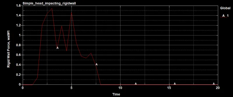
RIGIDWALL FORCE:
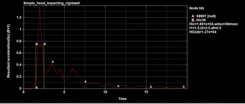
HIC36 value;
--------------------------------------- --------------------------------------- --------------------------------------- --------------------------------------- ---------------------------------------
CASE 2. HEADFORM AGAINST A RIGIDWALL
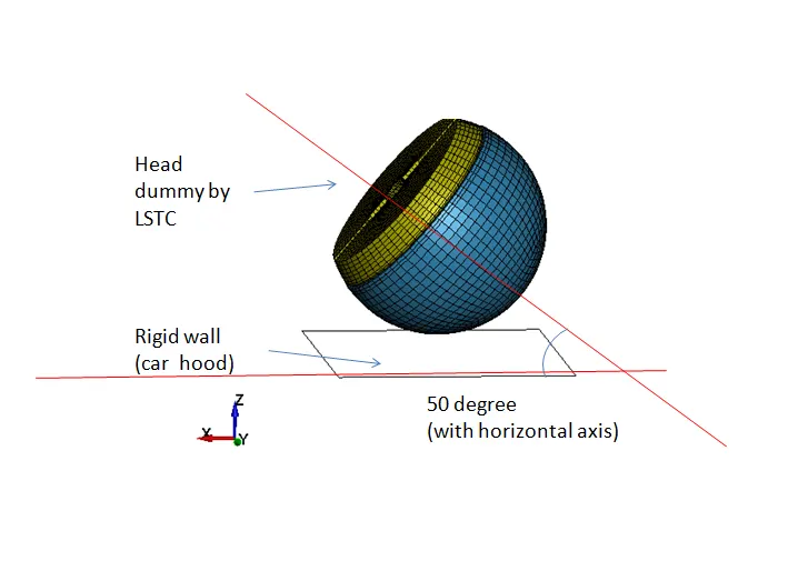
Unlike the previous case, where the head part was a complete sphere, this model involves translation and rotation of the pedestrian creating an impact angle of 45 degrees with the rigid wall and the bonnet. This can be done using the*INCLUDE_TRANSFORM and DEFINE_TRANSFORMATION keywords in a separate keyword file (.k or .dyn) and referenced to the headform model using the above-mentioned keywords such that any changes made don't directly affect the headform model which can act as a basis for all pedestrian safety analysis.
- DEFINE_TRANSFORMATION
This keyword has to be initialized before the INCLUDE_TRANSFORM to prevent errors. This keyword lets us perform certain transformations like SCALE, ROTATE, etc to the part file reference in the INCLUDE keyword. For our model, we will rotate the model about the x-axis at an angle of 50 degrees(as per Euro NCAP). This can be achieved by specifying the a1-a3 parameters which define the axis of rotation and a4-a6 the point through which the vector passes through and finally a7 where the angle of rotation in degrees can be specified.

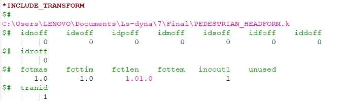
- INCLUDE_TRANSFORM
This keyword is a modified form of the regular *INCLUDE_INCLUDE keyword file, that it helps us make changes/ transform the imported model prior to creating it on the viewport. Certain offsets of IDs can also be changed however since our model consists of very few parts we will not use the offset command.
It is used so that whatever changes we do for the part, for a particular analysis are not reflected on in others.
- PART - SECTION & MAT
The section and material properties will be already defined in the dummy model provided by LSTC
The headform part which has to replicate the behavior of a real pedestrian head is modeled using a SECTION_SOLID. Since this headform part constitutes of different sub-parts, each sub-parts are modeled using different materials with the Skull, Accelblock, Backplate modeled using a MAT_20_RIGID material, and the Skin with a MAT_77_O-OGDEN_RUBBER which is a type of hyperelastic material.
The rest of the keywords - *CONTACT_AUTOMATIC_SINGLE_SURFACE, *CONTROL_TERMINATION & ENERGY, DATABASE_ASCII_Output & BINARY_D3plot & HISTORY_NODE_SET, *RIGIDWALL_PLANAR are created with the same parametric values as used for the Simple head model.
POST-PROCESSING
The Von-mises stress experienced by the pedestrian head model is shown below,
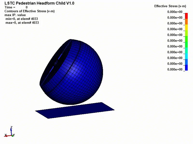
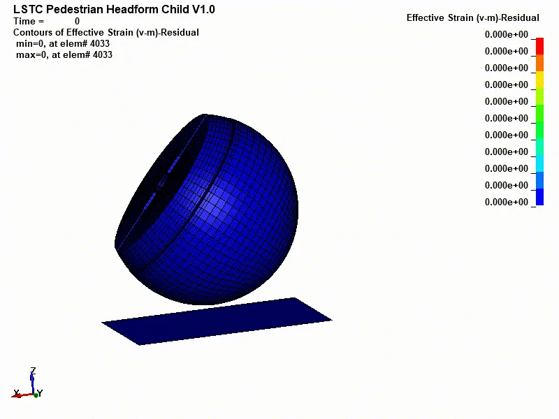
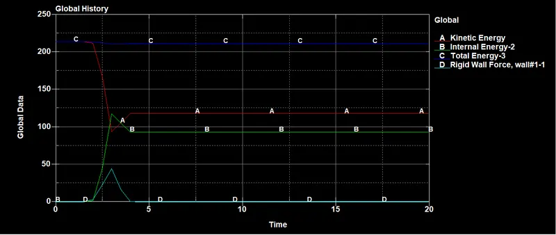
The ASCII_Outputs referenced in the DATABASE card namely the GLSTAT and NODOUT results are shown below,
From the above graph, we can clearly understand the energies developed during the impact. From the d3plot we can visualize that the impact occurs at a time step of 1 ms and from hereon the stress experienced by the headform gradually increases which leads to a gradual increase in the internal energy developed on the model and a simultaneous drop in kinetic energy of the model.
Similarly, we can see a gradual increase in the hourglass energies developed which changes non-linearly after the point of impact. However, the stonewall energy experienced in the rigid wall is relatively low, the reason being it has more stiffness and the impact of headform doesn't cause stress occurrence at the wall. This is a valid result since the same would occur in real life if the pedestrian head were to collide with the bonnet of a car i.e the head would acquire more damage than the bonnet.
The resultant nodal acceleration is shown below,
The HIC coefficient plotted along with the resultant acceleration for a selected node in the headform is shown below,
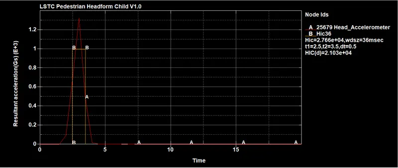
This is a relatively low HIC value considering the impact was calculated from a relatively low distance of about 10 -15mm from the rigid wall. The above HIC value represents a very minor head injury which according to the AIS (Abbreviated Injury Scale), there is a high probability of migraine and small concussions but with very little probability of severe skull fractures.
However, in real cases, the damage could be significantly high considering the acceleration factor as it increases at a sudden rate when calculated from a significant distance of the head from the bonnet of the car.
This modification will be made while simulating the same with a bonnet in the next case
--------------------------------------- --------------------------------------- --------------------------------------- --------------------------------------- ---------------------------------------
CASE 3: HEADFORM AGAINST A BONNET
This case involves the same simulation but the impact occurs on a bonnet similar to real-life pedestrian accidents. From the results mainly the HIC36 value obtained from the previous simulation, few minor changes have been made to the part so as to replicate a real pedestrian accident. This is achieved by taking into consideration of the civilian distance from the bonnet and the velocity rate at which it occurs while maintaining the velocity at 40 kmph.
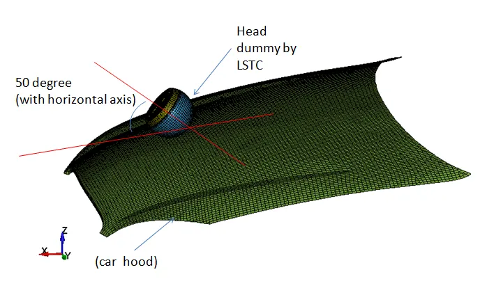
The regular keyword changes are,
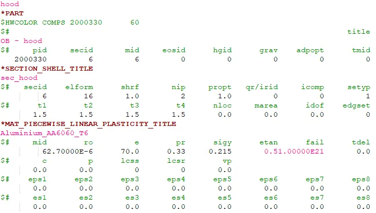
- PART - SECTION & MAT (HOOD)
Normally thickness of the hood will be about 1.5 to 2.5 mm so we are using a 1.5 mm model.
The hood in order to replicate that of a real-life scenario is not modeled as a rigid wall since the stiffness of a rigid wall is significantly high to experience a considerable deformation under high rate impact circumstances. Hence the hood is modeled using an Aluminium material using the MAT_ELASTIC keyword.
- CONTACT_AUTOMATIC_SURFACE_TO_SURFACE
Unlike previous cases involving rigid walls, where the contact between any part model and the created rigid walls are pre-existing hence while considering the contact between any other models excluding a rigid wall has to be initialized. For successful contact in an impact test, the models are compiled onto a SET_SEGM since specifying segments during contact are more appreciable than parts/node sets.
Thus the create SET_SEGM are referenced in the AUTOMATIC_SURFACE_TO_SURFACE card with the Slave ID being that of the Head model and the Master ID relating to the segments of the BONNET.
The rest of the keywords are created similar to previous cases.
POST-PROCESSING
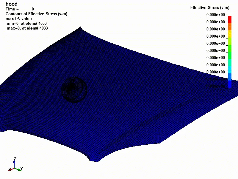
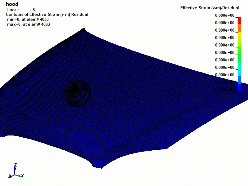
The Von-mises stress generated during impact is shown below,
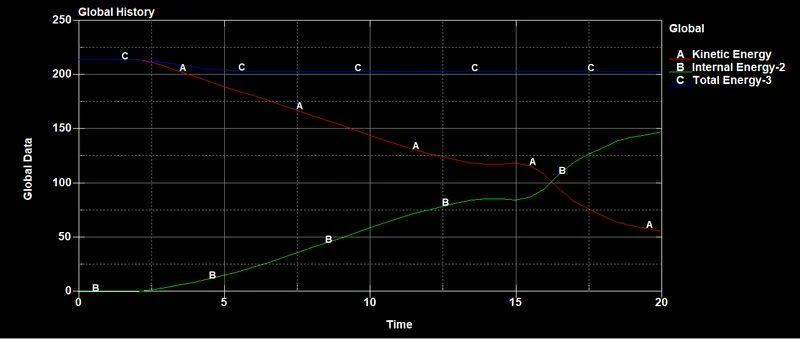
During impact, most energy is absorbed by hood deformation(which is large in this case). so HIC value is small.
TheHIC36 value of the simulation shown below,
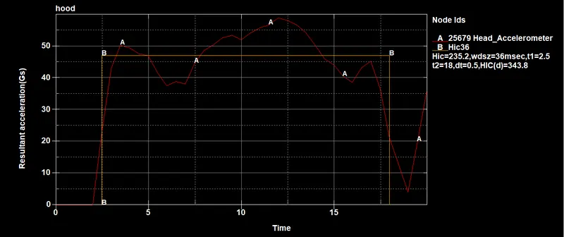
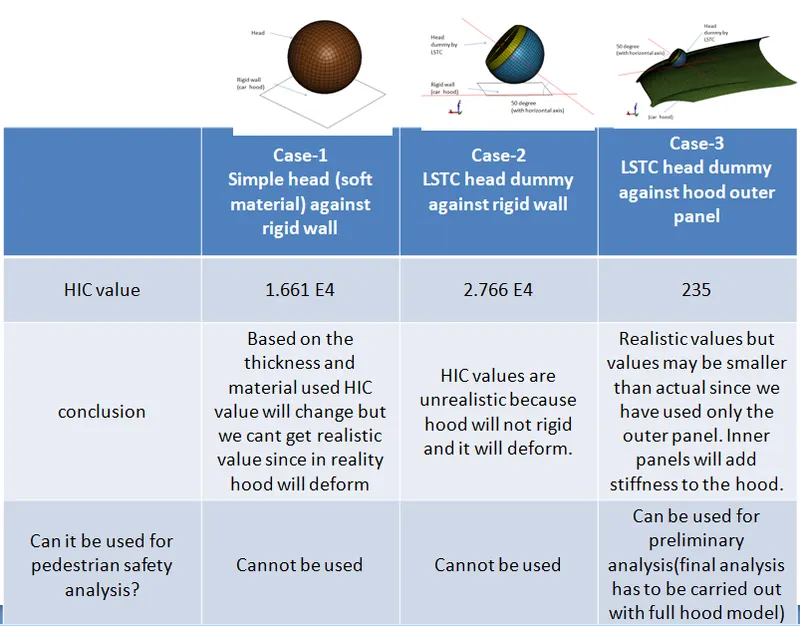
It is obvious that we would experience a high HIC value considering the modified parameters and the high stress and permanent deformation experienced by the part. In this case, we get a HIC value of 235 which is a relatively small value comparing the previous case.
This high HIC value could mean, the dummy (pedestrian) could experience severe damage to the head with a high possibility of high concussion along with multiple skull fractures, neurological damage, and possibly even death.
CONCLUSION:
1. The impact simulation of pedestrian headform is created for a simple case scenario to a complex real-time scenario i.e.,
case (1): Simple head model impacting against a rigid wall
case (2): Child headform model impacting against a rigid wall
case (3): Child headform model impacting against the hood.
2. The computational time required for the simple case is less but the accuracy of the results is
poor for a simple case.
3.From the above-gathered simulation data and results, we can conclude that depending on the velocity rate, distance, cross-sectional area, material, and various other factors could alter the impact results causing either low injuries like concussions or severe injuries like skull fractures for the pedestrians involved.
3.Different HIC values are due to different material properties and boundary conditions. so the best option is to use a standard dummy model and car model with all necessary parts for the simulation.