Week-7 Head Impact
HEAD IMPACT,
Objectives,
To perform the Head Impact Simulation and calculate the HIC-(Head Injury Criteria/Co-efficient) value in the LS-PrePost.
1. Simple head model will impact on the rigid wall.
2. Child head form impact on the rigid wall.
3. Child head form will impact on the hood, This hood should be considered as a rigid wall.
Introduction,
Current accident analysis shows that the head of the pedestrian impacts most frequently into or around the windscreen since cars in recent have a short hood. Therefore, the injury risks to the head in contact with various locations of the car including the windscreen and its frame were examined based on head form impact tests. The HIC is high from contact with the cowl, lower windscreen frame, or A-pillar, and it is low with increasing distance from these structural elements. In the windscreen center, the HIC is less than 500.
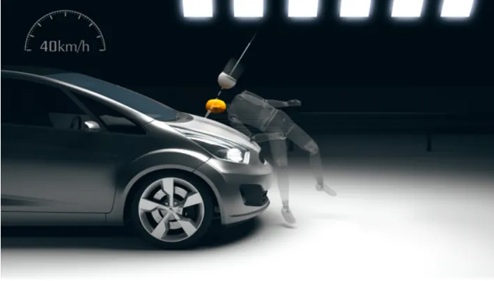
Head Injury Criteria(HIC),
The equation used for the measurement of the head injury of the whole model for the pedestrian head impact was head injury criteria (HIC). It has been used to predict the risk of engine hood to a pedestrian during the collision.

Small HIC values don't mean that the head injuries will be of low levels. Likewise, a high HIC doesn't imply high-level injuries. The real meaning is that with higher HIC values, higher the probability of getting high-level head injuries.
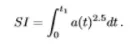
The severity index isn't for the head. It can be used any part and any kind of impact of the body. It takes the Everest acceleration for the small-time interval, where the acceleration and acceleration happen a certain duration. And then you take a certain exponent to Everest accelerating and integrity over time, So its called the severe index.
Procedure,
In this study, a children's head form model is provided. Where this head form will impact on a car bonnet. The bonnet should be considered as a rigid wall for the 1st case and while using the meshed hood model an elastoplastic material card has to be used. From the simulation, the head impact coefficient must be calculated manually and with the help of LS-PrePost.
1. Simple head impact on the wall,
The simple head models it's given with the statement. This model meshed with shell elements and impact on the planar rigid wall at normal to the Z-axis 10mm away from the model.
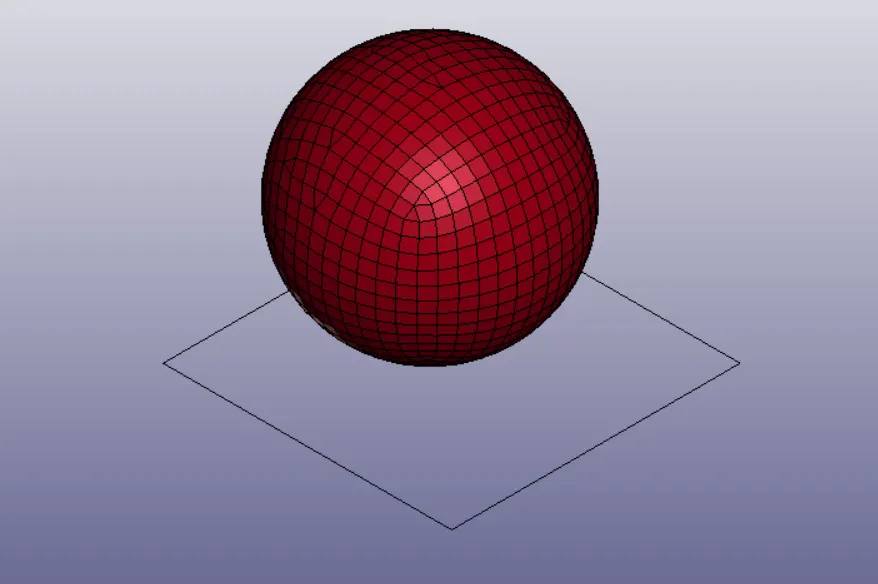
Fig 1.Simple head with planar rigid wall at bottom of the model
The section properties of the simple head using the *SECTION_SHELL card. Assign ELFORM is 2 and the thickness is 14mm. Then material properties are assigned by using *MAT_ ELASTIC card.
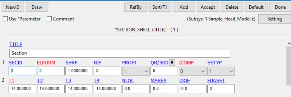
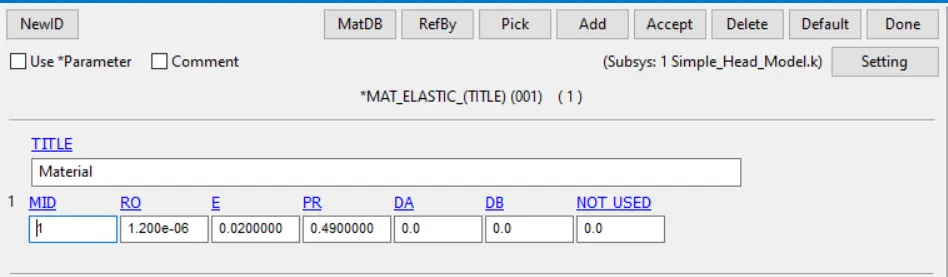
Fig.2. Section and Material properties assigned to the geometry
The model is assumed to have 40KmpH velocity along the traveling path which 45 degrees along the Z-axis. So assume the impact of simple head-on the rigid wall at 45 degrees and the velocity 7.85mm/ms to the geometry along the X and Z axis in opposite direction. This type of Circular shape in geometry, operation of rotating, and translating it don't make any changes in impact simulation.
Automatic single surface contact is defined as this simulation, slave segments only defined is required for this contact type. Geometry is assigned as the slave segments and the master segments column kept empty.
The termination time of this problem is defined by using *CONTROL_TERMINATION card. HIC value extracted through the NOD OUT card at *DATABASE_ASCII option. Material energies are extracted using the MATSUM card. Force extracted on the rigid wall uses the REFORM card. And here bottom-most node is selected for extracting the results. *DATABASE_HISTORY_NODE card used to select the bottom-most node. Binary D3Plot is activated in the database section to get the final impact simulation.
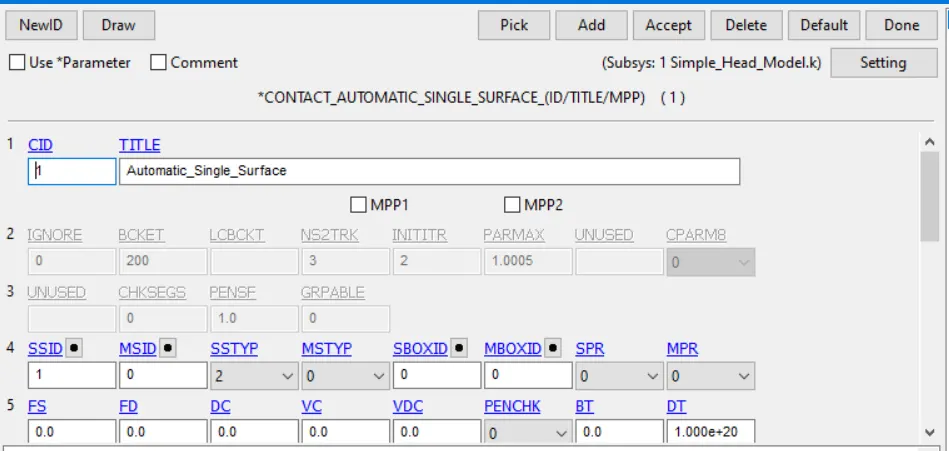
Fig.3 Geometry is assigned by single surface Contact
2. Head form impact on the rigid wall,
Child head form is given with a problem statement. In this case, consider the impact of the head on the rigid wall at an angle 45 degree. But given geometry isn't a perfectly circular shape. So, the transformation of the original geometry is necessary to replicate the real impact situation. *DEFINE_TRANSFORMATION card used to rotate the original body about the Y-axis and *INCLUDE_TRANSFORM card used to complete the rotation procedure. This card, the original head geometry is called through filename and defines the Transformation (TRANID=1) is carried out the geometry. Further, these required keywords are added to the new input file. The original input file isn't changed but only called for transformation. Both keyword files, the original input file, and new input files are kept in the same folder.
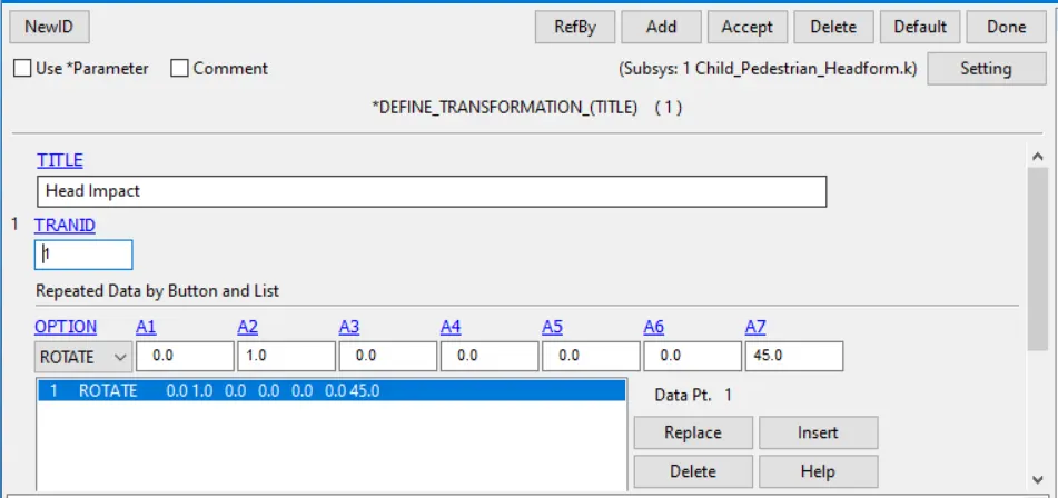
Fig.4. Define Transformation card for rotating the geometry
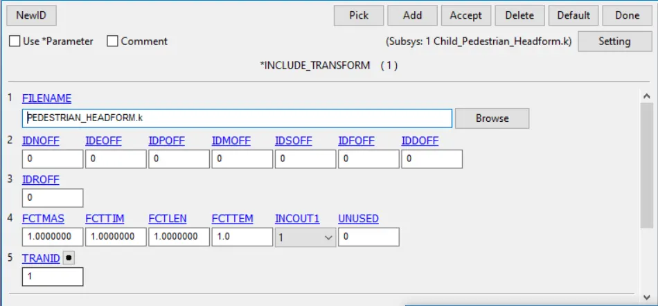
Fig.5. Include Transform card
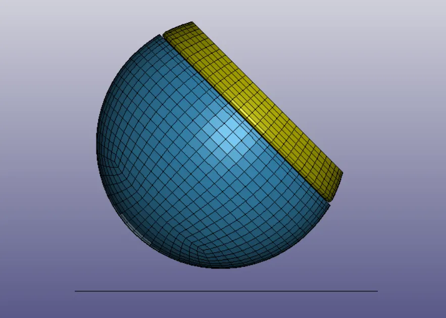
Fig.7. Transformed Geometry
After that, a rigid wall is generated normal to Z-axis. Head geometry is made up of solid elements. The whole geometry is made up of four different parts like skull, skin, accel block, and backplate all these parts are modeled with solid elements. Assume the impact of simple head-on the rigid wall at 45 degrees and the velocity 7.85mm/ms to the geometry along the X and Z axis in opposite direction.
The Control energy cards also pre-defined to determine all energy. All the details have the original geometry file so don't change it and kept as default. The timestep card has defined this analysis. Ls-Dyna calculates the time step automatically for all the elements and uses the minimum value for the analysis. The termination time is given to replicate the impact. These input files are saved as a new.k file.
3. Head form impact on the head,
In the third case is performing and analyzing the head form impact on the hood. The impact direction with a velocity of the head form impact on the hood is kept the same as the previous case. *DEFINE_TRANSFORMATION and *INCLUDE_TRANSFORM card used for head form from the previous case is used as it is. Then, *INCLUDE card used to include the hood model. This input file is saved as a different.k file which will be solved by the solver.
Before that, open the hood model. This file only meshes with geometry data. So, assign the material card(Piecewise_Linear_Plasticity_024) and section card(*SECTION_SHELL) along with that.
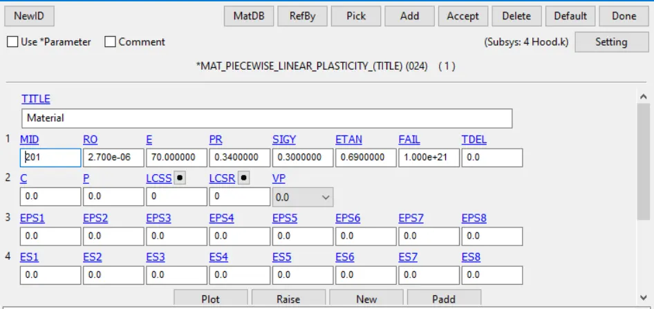
Fig 8. Material Properties for the hood model
AUTOMATIC_SURFACE_TO_SURFACE contact has been defined between the hood and head form, where hood as master and head form as slave. The initial velocity -7.85mm/ms is defined along X and Z direction to the head form impact on the hood. Boundary Spc has created for the hood is constrained all the DOF set of nodes(NSID) on the edge of the hood.
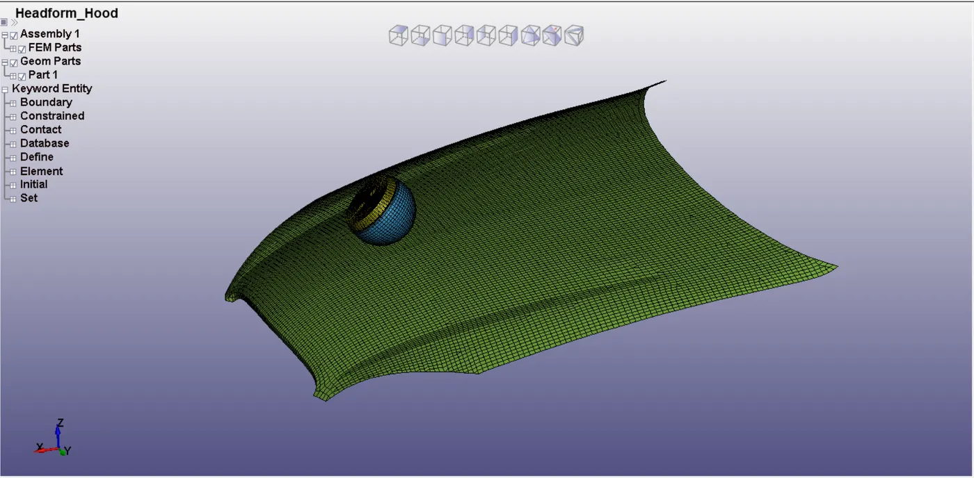
Fig.9. Headform Geometry with hood
Termination time is given to consider the impact and after the effect. GLSTAT, RCFORC, SLEOUT, MATSUM cards are defined to set the post-processing results. Binary D3Plot-defines the frequency at which the animation files are created. History nide is defined to measure the acceleration and calculate the HIC value.
Results,
Effective Stress Values,
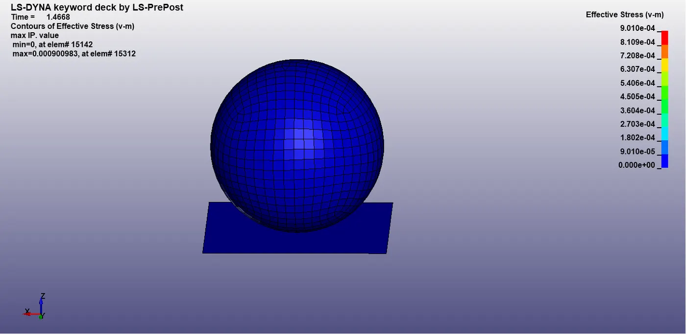
Fig.10 Effective Stress on the simple head impact on the wall
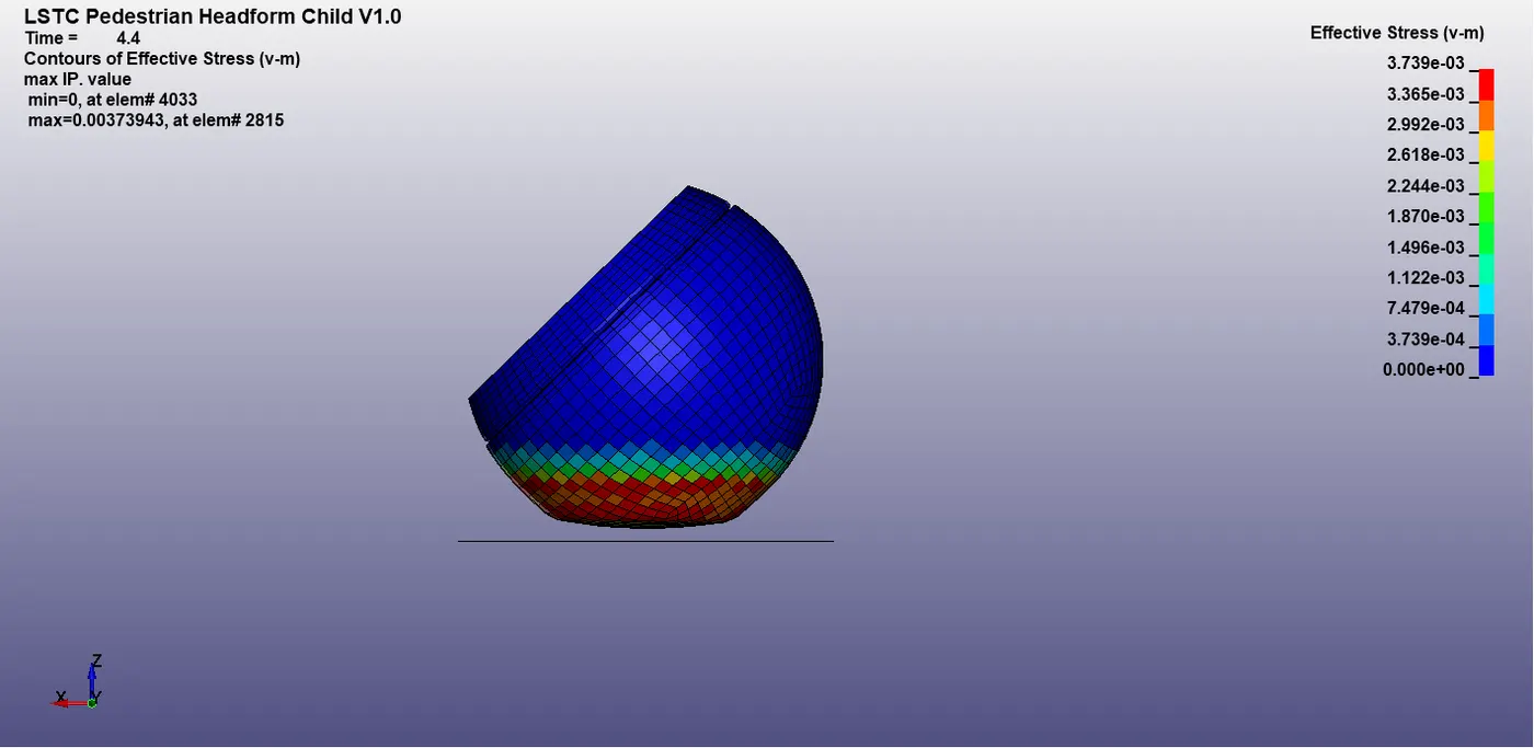
Fig.11 Effective Stress on the Head form impact on the wall
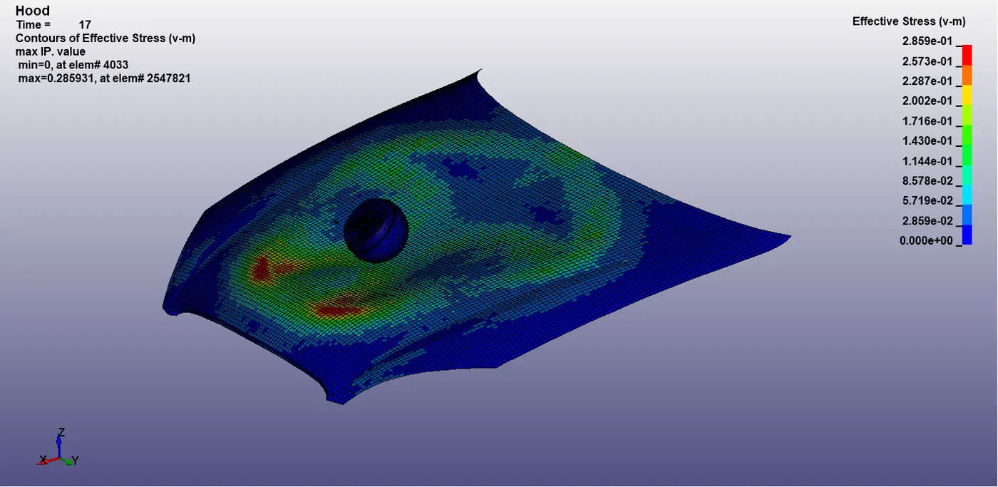
Fig.12 Effective Stress on the head form impact on the hood
In fig 10 Stress values are higher at the instant of impact and reduce fluctuation after the impact. Because the material is elastic and maximum stress acting on the head 9.01e-4 GPA. In fig 11 Shows the effective stress on the head form on the rigid wall where the material properties have been already pre-defined. It shows the different behavior of its significant deformation in geometry after the impact. In fig 12 shows the effective stress on the head form impact on the hood. Elastoplastic material has been defined as the hood.
Effective Strain,
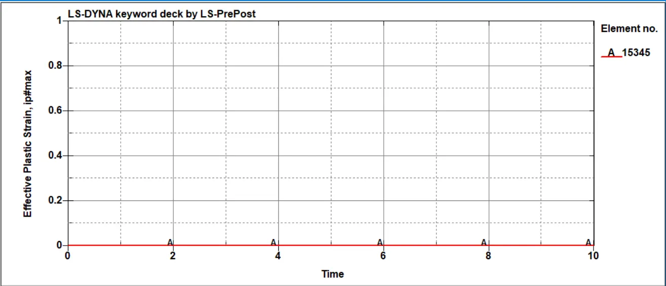
Fig 13. Total Strain Impact of simple head geometry
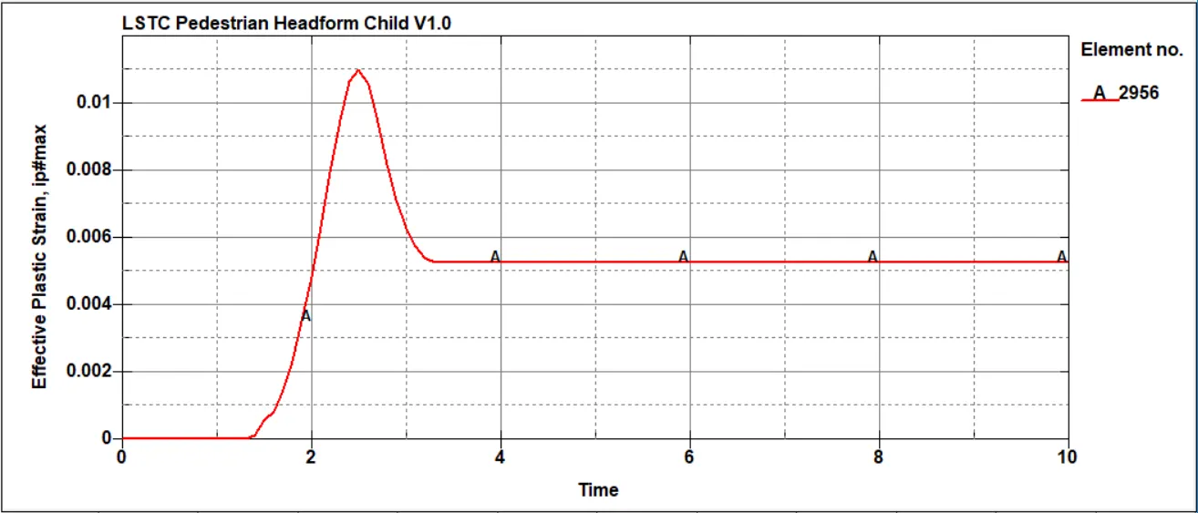
Fig 14. Total Strain Impact of Headform on the rigid wall
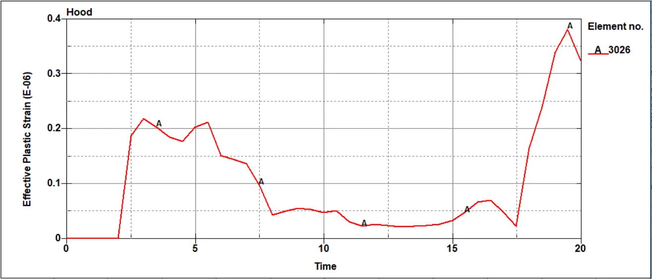
Fig 15. Total Strain Impact of Headform on the Hood
Strain values for all the three cases are extracted on the head geometry. Select bottom nodes of head geometry have extracted the strain values. In fig 13 shows the total strain values of a simple head on a wall. where total strain vale is zero throughout. That there deformation of simple head geometry after the impact this relates to the very low strain values. Fig 14 shows the total strain values of head form on the wall. where the after the impact Strain value is increasing simultaneously after that 2.4ms drop the strain value. After the impact elastic strain recovery fully but plastic strain deformation permanent till the end. In fig 15 Shows the total strain impact of head form on the hood. Strain values are on the head form slightly same to case 2 because the same head form use the case. But case 3 use the hood instead wall. Hood has aluminum material properties that's the main reason for peaks and valleys shows on the strain graph.
HIC36,
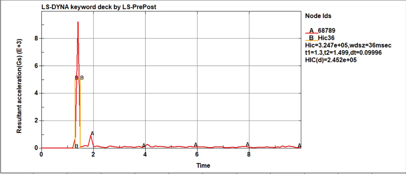
Fig 16. HIC 36 simple head impact on wall calculated in LS-DYNA
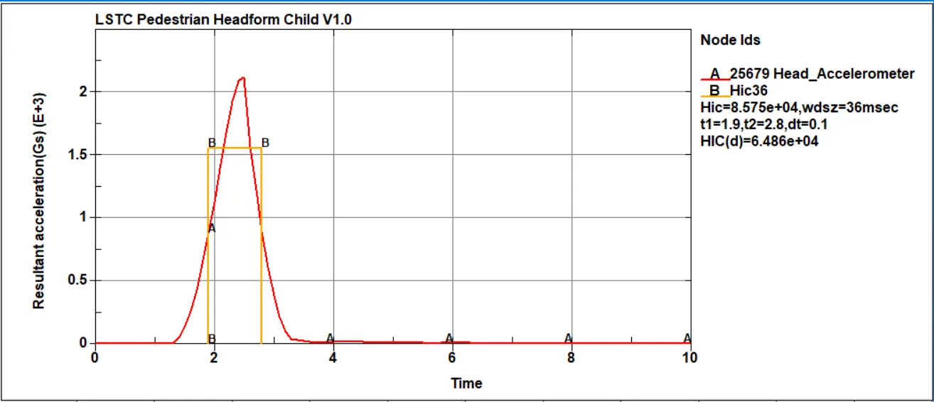
Fig 17. HIC 36 headform impact on wall calculated in LS-DYNA
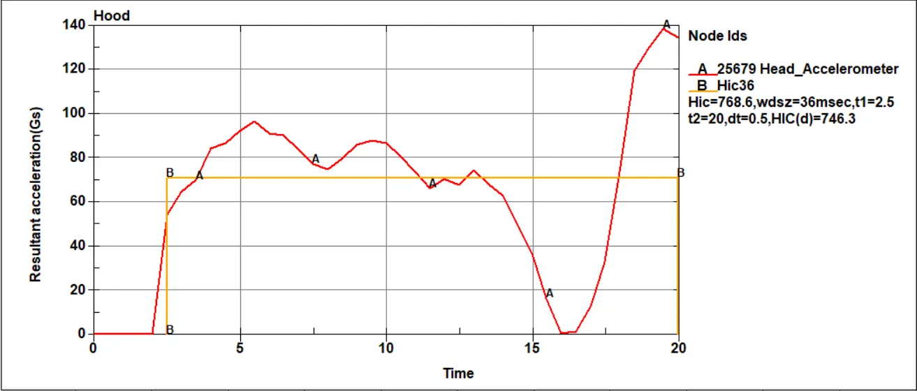
Fig 18. HIC 36 headform impact on hood calculated in LS-DYNA
HIC values from the accelerometer at the center of mass of the crash. In fig 16 shows the HIC 36 simple head impact on the wall where impacxt is 3.247e+6. And figf 17 show the HIC 36 shows the headform impact on the rigid wall where impact is 8.575e+4. Thats HIC values of this two cases compared, the resultant acceleration is inctreased and decreased after impact. because the body after the impact come to hold and again back. In fig 18 shows the headform impact on the hood. Here HIC values is 768.6.
Conclusion,
The first case simple head impact on the wall, The simple head geometry deformation is small level because elastic material card assigned with it. And strain values negligible after the impact. The HIC values calculated with high acceleration with small timiing period.
Second case headform impact on the rigid wall, this case gives better ideas about the impact with rigid wall. rigid wall is undeformable so total stress act on the head form and HIC values higher than previous case.
In Third case is headform impact on the hood, this case assign the aluminum material to the hood given stress on the head form total stress, an area of stress acting on the hood. That is reason for elastic stress and strain minimum level compared to the another cases with same to the HIV values.