Child Pedestrian Head Impact Simulation and HIC value calculation in Ls Dyna
Objective: To perform head impact analysis and calculate the HIC (Head injury criteria/coefficient) value
- First case: Simple head-model and rigid wall
- Second case: Child head-foam and rigid wall
- Third case: Child head-foam and bonnet
Introduction:
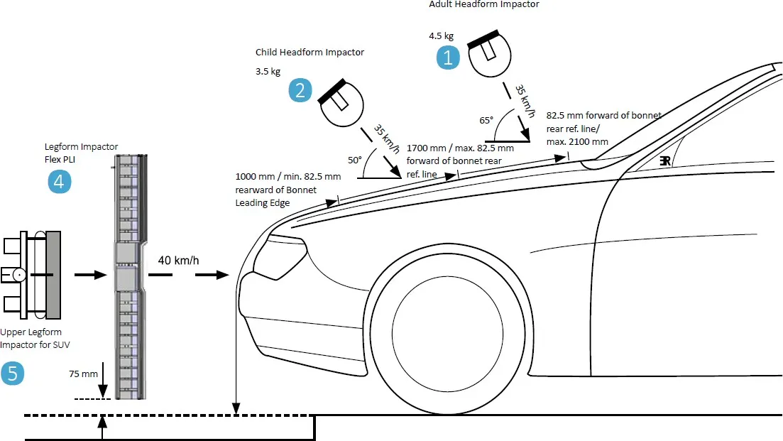
Car-pedestrian accidents account for a considerable number of automobile accidents in industrialized countries. Head injury continues to be more concerned with Automobile impacts. Because the head is the most seriously injured part in many collisions including in pedestrian automobile collisions. To reduce the severity of such injuries international safety committee have proposed subsystem tests in which headfoam impactors are impacted upon the car hood
Currently in India, Automotive Indian Standard (AIS) 100, Amendment 1 is used to evaluate the performance of vehicles against pedestrian safety. This standard has been harmonized from the international evaluation standard Global Technical Regulation No. 9 (GTR 9), whose purpose is to bring about an improvement in the construction of the fronts of vehicles and, in particular, those areas which have been most frequently identified as causing injury when in collision with a pedestrian or other vulnerable road user. The tests required are focused on those elements of the child and adult body most frequently identified as sustaining an injury, i.e. the adult head and leg and the child's head. To achieve the required improvements in the construction of vehicles, the tests are designed in such a way that they will represent the rear world accident scenario.
Head injury criteria (HIC)
headfoam impactors are used to test the behavior of vehicle structures such as the hood. In a pedestrian-vehicle impact, the kinematics and severity of pedestrian injuries are affected by the impact locations on the vehicle and body velocities after impact. The objective of this project is to analyze the pedestrian kinematics in a Pedestrian-Car accident scenario and determine the Head Injury Criteria (HIC) from the head resultant acceleration, for head impacts on the vehicle hood
The equation that used for the measurements of the head injury of the whole model for the pedestrian head impact was head injury criteria (HIC). It has been used to predict the risk of engine hood to a pedestrian during the collision
HIC is calculated according to the below Equation

Where
- a: the resultant acceleration (as a multiple of 10 ms-2 or about 1 g
- t1, t2: two-time instants (in seconds), which define the start and end of the recording when HIC is at maximum. Values of HIC at the time interval t1-t2
PROCEDURE
- First case: Simple head-model and rigid wall
Geometry:
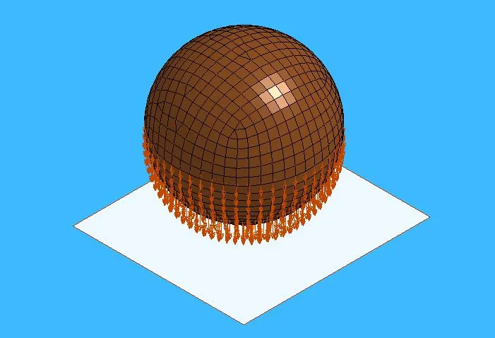
- The simple head model is imported and there are meshed which shell element
- The planar rigid wall is created normal to the Z-axis and placed 15 mm away from the simple head geometry
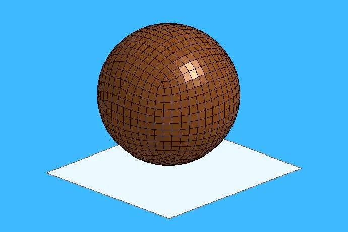
Kg/mm/ms unit system is used throughout the analysis.
Section Creation :
Section Creation Define Section Properties for different element
Since the Simple headfoam are meshed using 2d element we will define them with the SECTION_SHELL card
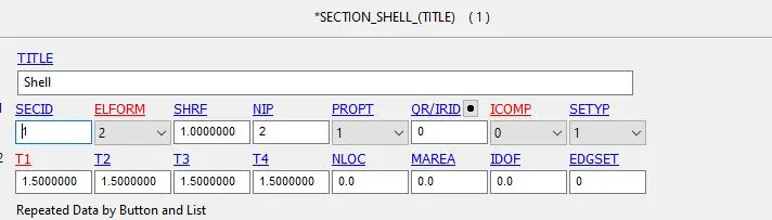
- SECID Section ID. SECID is referenced on the *PART card. A unique Number or label must be specified.
- ELFORM Element formulation options.= 2 Belytschko-Tsay (default)
- SHRF Shear correction factor which scales the transverse shear stress.= 1
- NIP Number of through-thickness integration points = 2
- T1 Shell thickness = 1.5mm
Material Model
We are supposed to define a material card for the Head foam
- We are using the MAT_ELASTIC card for head foam

The material and section are assigned to their respective part ID’s
Boundary Condition:
The Initial Velocity is defined to the Head foam to impact the rigid wall
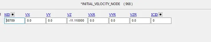
We assume in this case the initial velocity is 40kmph i.e - 11.11 mm/ms in negative z-axis which is toward the rigid wall
Control Cards:
Control_Termination is defined at what time the simulation ends or the end time of the simulation. It is set to 1.65ms
Database Creation
- BINARY_D3PLOT - It defines the frequency at which the animation file is to be created and is set to 0.01ms
- DATABASE_HISTORY_NODE A nodes on the bottom face of head were defined in the to measure the acceleration and calculated HIC value
ASCII_option keyword
The output request in ASCII format, The following keyword are Activated
- GLSTAT- Global Data
- MATSUM- Material Energies and
- NODOUT- Nodal point data
- RWFORC : Rigid wall force
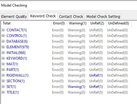
Keywords & Model Checker :
Results :
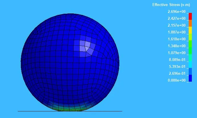
Effective stress values:
Max Effective Stress: 2.69GPa

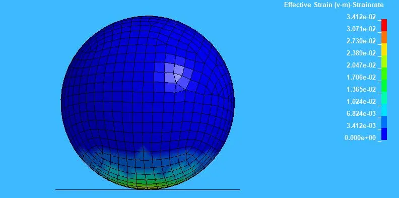
Effective strain values:
Max Effective Strain: 0.0341
- Second case: Child head-form and rigid wall
Geometry:
The test setup as per AIS 100. The release angle was 50⁰ for the child headfoam. The headfoam velocity at impact was 11.1mm/ms (40 km/h) for headfoams. Impact point on the Rigidwall instead of car hood in this case
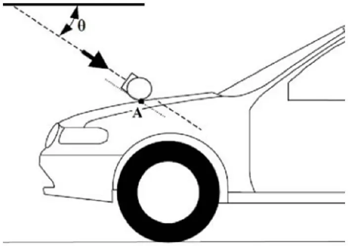
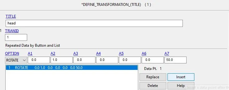
Since the transformation of the original geometry is necessary to replicate the real impact situation. *DEFINE_TRANSFORMATION card is used to rotate the original body about Y-axis. *INCLUDE_TRANSFORM card is necessary to complete the rotation procedure. In this card, the original geometry is called through filename and defined transformation is carried out on that geometry. Transformation ID(TRANID) is set to 1 for this card. A separate keyword file is created with these keywords. The original input file is not changed but only called for transformation. Further required keywords are added in this new input file. Both the keyword files the original input file and the new (transformed) input file are kept in the same folder
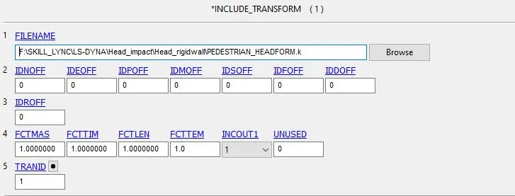
The Child head FE assembly model is imported
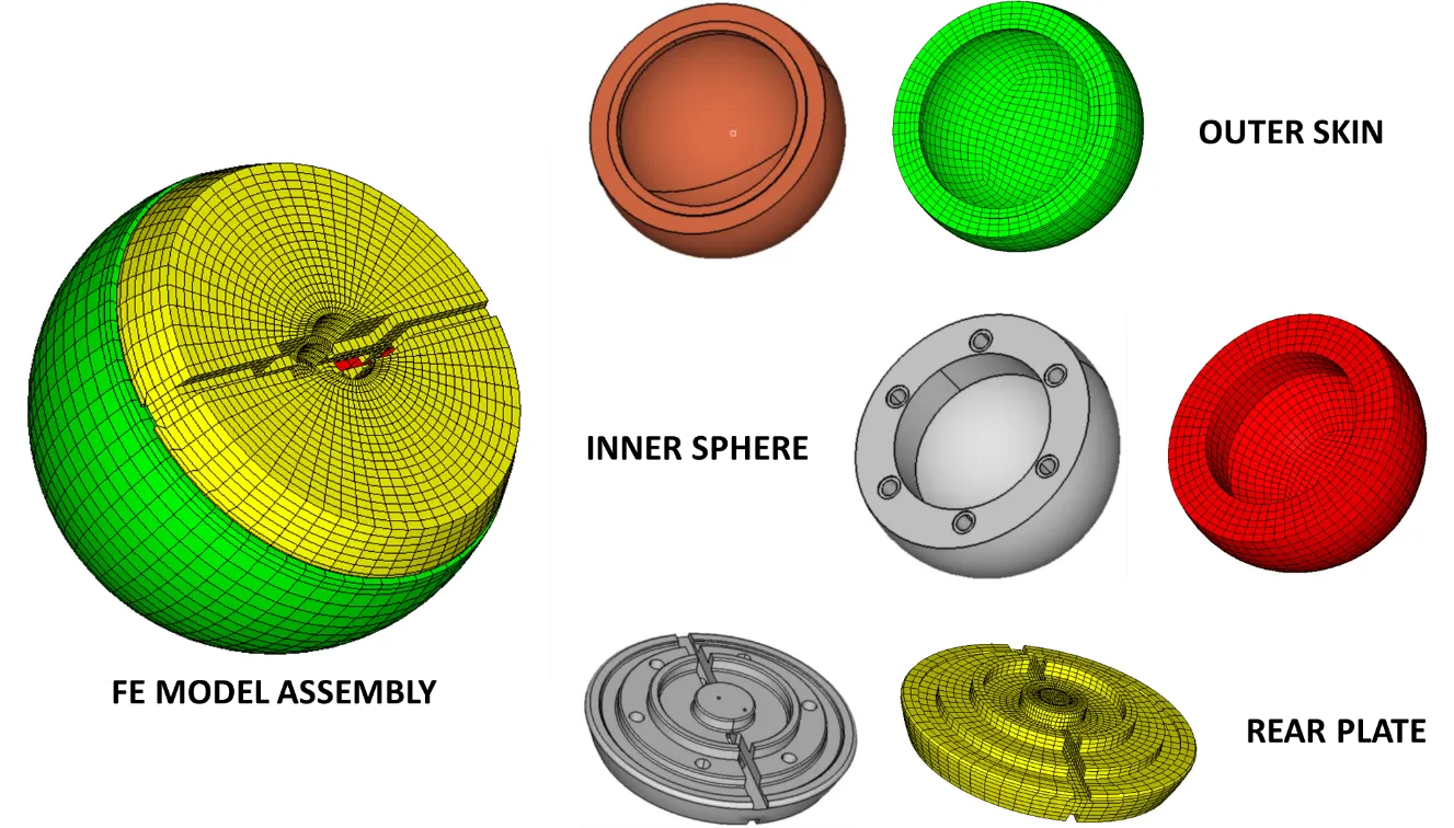
Accelerometer element was placed on the rear plate inside the inner sphere recess at the same location as its counterpart in the physical headfoam. *CONSTRAINED_EXTRA_NODES_SET was used to assign contact between outer skin and inner sphere of headfoam. *CONSTRAINED_RIGID_BODIES was used between back plate and Sphere and acceletometer block. *CONTACT_AUTOMATIC_SURFACE_TO_SURFACE_ID was used to assign contact between outer skin and inner sphere
Each component of the physical headfoam and the complete assembly were weighed to obtain their masses. Density values of each component were adjusted based on the geometry scanned and total mass weighed.
The final FE child headfoam model masses were 3.51 kg. These were within the allowable tolerance as per AIS 100 (+/- 0.07 kg for Child headfoam)
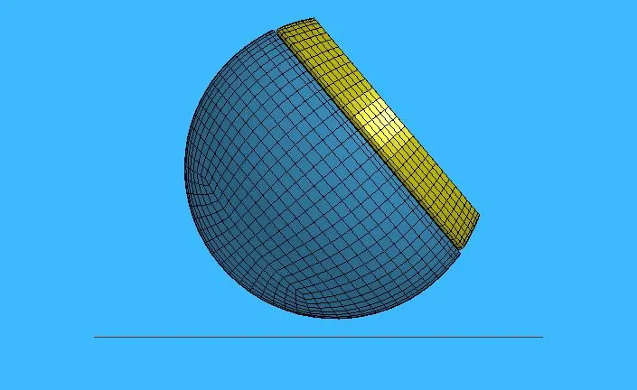
The rigid wall is generated normal to Z-axis as discussed in the previous Case and placed 15 mm away from the child headfoam model
The material card and section card is already predefined for the child head foam assembly
Boundary Condition:
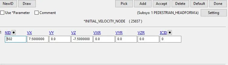
The Initial Velocity is defined along X and Z direction to the Head foam to impact the rigid wall
An initial velocity of 11.11mm/ms is with which the Head impacts the rigidwall but in here the it will be a projectile(resultant) motion. So, the component motion in x and y direction has to be calculated.
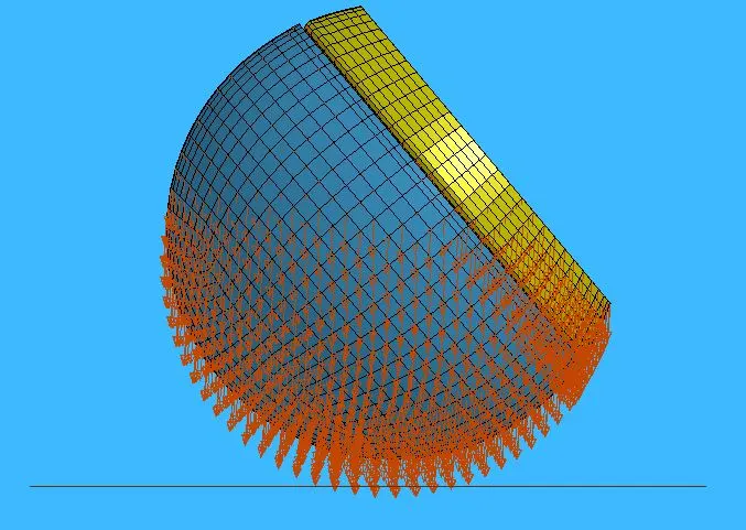
We assume in this case the initial velocity is 40kmph i.e 11.11 mm/ms in negative z – axis but in this case the head is tilted above 50⁰ so the velocity component as to resolved along X and Z direction
The velocity of 7.500 mm/ms is given to the geometry along X and negative Z direction.
Control Cards:
Control_Termination is defined at what time the simulation ends or the end time of the simulation. It is set to 4ms
Control Time step : calculates the time step automatically for all the elements and uses the minimum value for the analysis
- TSSFAC (Scale factor for computed time step) = 0.9
- DT2MS(Time step size for mass scaled solutions) = - 0.0011000
DT2MS - Negative: Mass is added to only those elements whose time step would otherwise be less than target time step size = (TSSFAC*|DT2MS|.)
Database Creation
- BINARY_D3PLOT - It defines the frequency at which the animation file is to be created and is set to 0.1ms
- DATABASE_HISTORY_NODE A nodes on Accel Block of head were defined to measure the acceleration and calculated HIC value
ASCII_option keyword
The output request in ASCII format, The following keyword are Activated
- GLSTAT- Global Data
- MATSUM- Material Energies and
- NODOUT- Nodal point data
- RWFORC : Rigid wall force
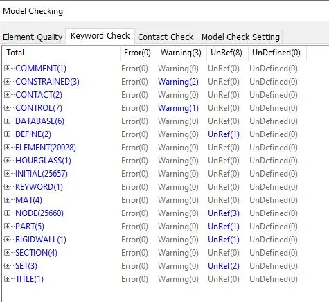
Keywords & Model Checker :
Results :
Effective stress values:
Max Effective Stress: 21.8 MPa
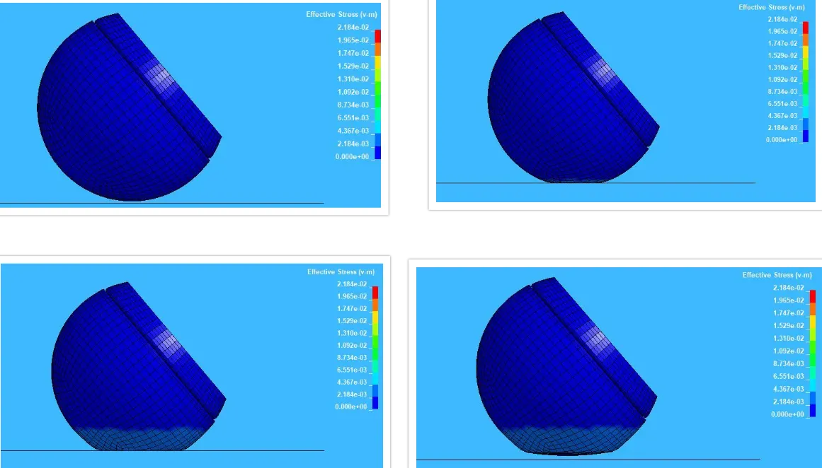
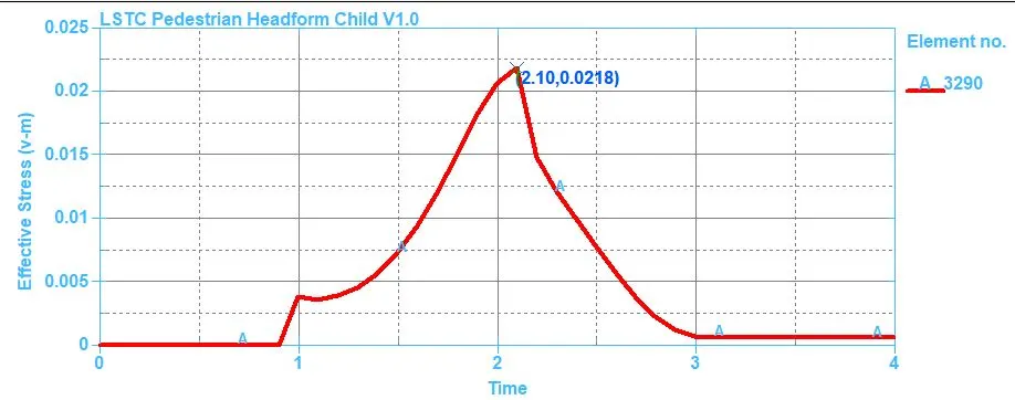

Maximum stress is 0.0218GPa at 2ms at the element 3002 and after that, the head foam rebounds and decreases drastically and maintains almost constant stress till the end of the simulation.
Effective Plastic strain values:
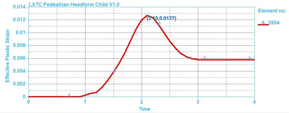
Max Effective Plastic Strain: 0.0127
In this case, the head foam is impacting the rigid wall with is undeformable, so all the stress will be acting on the head foam which eventually will have more deformation and we can see the total strain increases gradually during impact. and drops due to hyperelastic properties of the materials and stays constant
Head injury criteria (HIC):
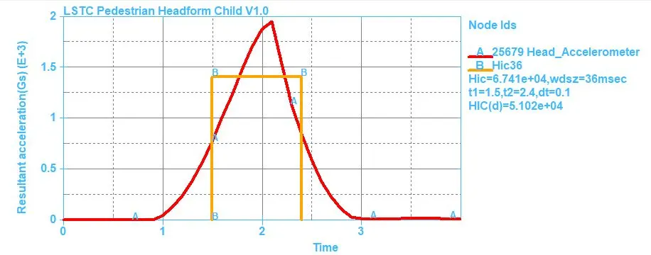
The HIC-36 value for headfoam impact is measured from an accelerometer place in the geometry. From the graph it can be seen, the resultant acceleration is increased and then decreased after the impact because the body comes to halt and again bounces back.
HIC : 6.741e+04
Energy Graph
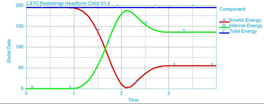
The energy plot for headfoam impact on a rigid wall, the kinetic energy decreases as internal energy increases at the of impact and since the headfoam is modeled with hyper-elastic material there is a gradual change in the energies after impact compared to the simple head model case Some of the energy is absorbed in deformation caused due to impact.
- Third case: Child head-form and bonnet
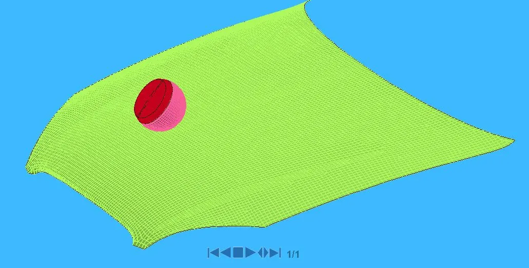
In this case, the rigid wall is replaced with bonnet to study the real-life situation of child pedestrian head impact simulation.
Geometry:
The meshed hood model in imported and The test setup is same as per AIS 100 with the release angle was 50⁰ for the child headfoam so like pervious case we will use *DEFINE_TRANSFORMATION and *INCLUDE_TRANSFORM to define position of the child head .
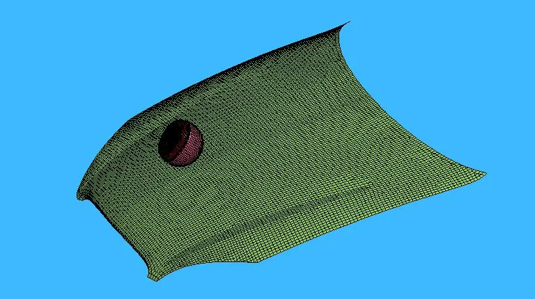
Since the Material properties and section properties are pre-defined only for the child head assembly and have to be defined for the car hood
Section Creation :
Section Creation Define Section Properties for different element
Since the Car Hood are meshed using 2d element we will define them with SECTION_SHELL card
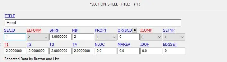
- SECID Section ID. SECID is referenced on the *PART card. A unique Number or label must be specified.
- ELFORM Element formulation options.= 2 Belytschko-Tsay (default)
- SHRF Shear correction factor which scales the transverse shear stress.= 1
- NIP Number of through-thickness integration points = 2
- T1 Shell thickness = 2 mm
Material Model
We will use Aluminium Material Properties For the Car Hood
Although many material models exist for metals, one of the most robust models is *MAT_024 or *MAT_PIECEWISE_LINEAR_PLASTICITY. This material model is the standard workhorse and is the recommended starting point for elastic-plastic simulation of metals and general plastics since it can also handle viscoelastic behavior (i.e., strain-rate dependency).
And for defining this material we are using MAT_024 (MAT_PIECEWISE_LINEAR_PLASTICITY), This is Material Type 24, which is an elastoplastic material with arbitrary stress
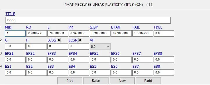
- MID Material identification. A unique number or label not exceeding 8 Characters must be specified
- RO Mass density.
- E Young’s modulus.
- PR Poisson’s ratio.
- SIGY Yield stress.
- ETAN Tangent modulus, ignored if (LCSS.GT.0) is defined.
Contact creation:
An AUTOMATIC_SURFACE_TO_SURFACE contact has been defined between Hood and headfoamHood as master and the headfoam as slave. As the headfoam has 5 components in it, the slave node set type is given as Part Set ID and hood as master segment type is also given Part set ID.
Boundary Condition:
- Initial velocity
The Initial Velocity is defined along X and Z direction to the Head foam to impact on the car hood
An initial velocity of 11.11mm/ms is with which the Head impacts the rigid wall but in here it will be a projectile(resultant) motion. So, the component motion in x and y direction has to be calculated.
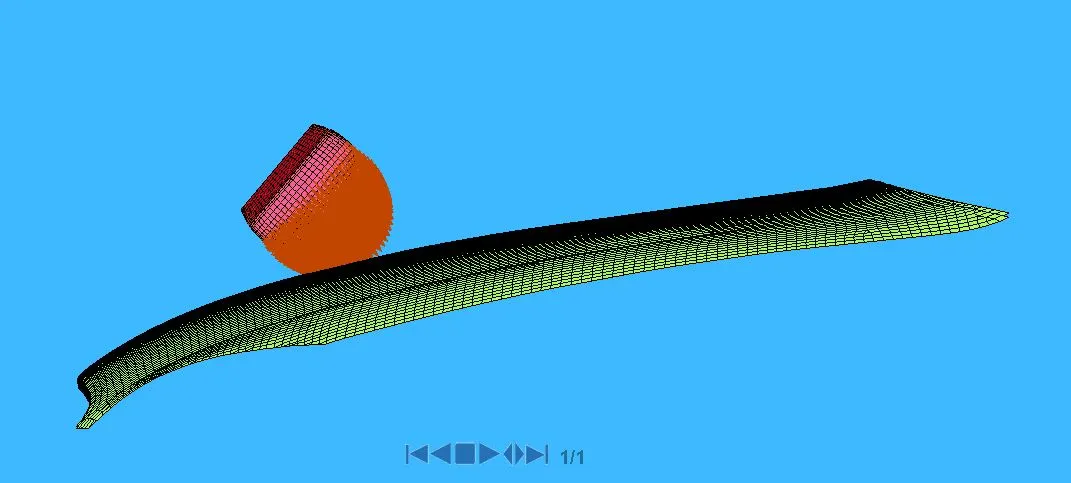
We assume in this case the initial velocity is 40kmph i.e 11.11 mm/ms in negative z-axis but in this case, the head is tilted above 50⁰ so the velocity component as to resolved along X and Z direction
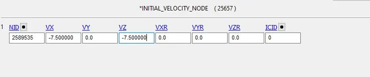
The velocity of 7.500 mm/ms is given to the geometry along negative X and negative Z direction
- Boundary SPC
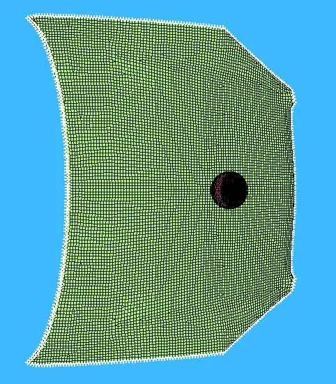
The Boundary SPC is defined for the Hood to constraint all the degree of freedom for the set of nodes (NSID) on the edges of the hood.
Control Cards:
Control_Termination is defined at what time the simulation ends or the end time of the simulation. It is set to 30ms
Control Time step: calculates the time step automatically for all the elements and uses the minimum value for the analysis
- TSSFAC (Scale factor for computed time step) = 0.9
- DT2MS(Time step size for mass scaled solutions) = - 0.0011000
DT2MS - Negative: Mass is added to only those elements whose time step would otherwise be less than target time step size = (TSSFAC*|DT2MS|.)
Database Creation
- *BINARY_D3PLOT - It defines the frequency at which the animation file is to be created and is set to 0.5ms
- *DATABASE_HISTORY_NODE A nodes on Accel Block of head were defined to measure the acceleration and calculated HIC value
- *DATABASE_EXTEND_BINARY - this writes the strain tensor to d3plot when STRFLG is set to 1
ASCII_option keyword
The output request in ASCII format, The following keyword are Activated
- GLSTAT- Global Data
- MATSUM- Material Energies and
- NODOUT- Nodal point data
- RWFORC : Rigid wall force
Keywords & Model Checker :
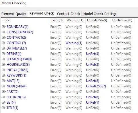
Results :
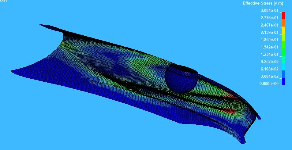
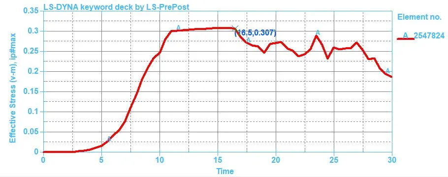
Effective stress values for Hood
Max Effective Stress: 30.8 MPa
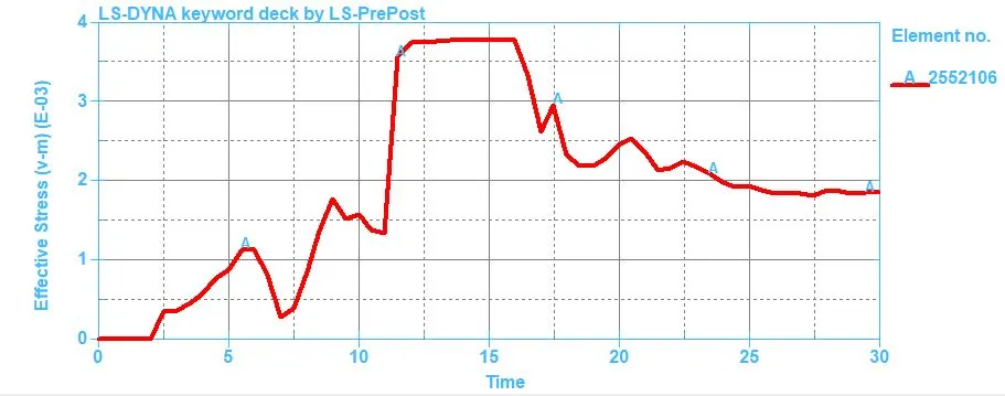
Effective stress values for head
Max Effective Stress: 3.8 MPa
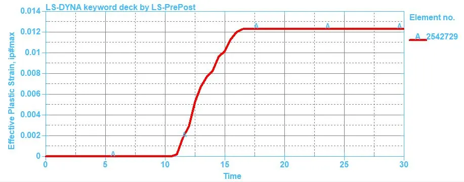
Effective Plastic strain values:
Max Effective Plastic Strain: 0.0123
In this case, the hood was defined with a piecewise linear plasticity material model which is a deformable model so during the impact the hood deforms significantly and reduces stress and strain on the head foam. The effective plastic strain showed on the graph is for the hood components because there was no deformation in the head model.
Displacement of Hood:
Max Displacement on the area of contact: 51mm
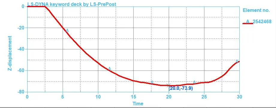
The Deformation starts as soon as the head foam comes into contact with the hood at 2.5ms they gradually decrease to 74mm at 20ms and once the head moves from that contact region due to the elastic properties of the hood material they try to retain there an original shape that's why we can notice an increase in curve after 20ms.
Energy Graph
Because of hood deformation, we can see kinetic energy decreases and internal energy increases gradually but in another case because of head foam impacting on the rigid wall there was an abrupt change in energy at impact

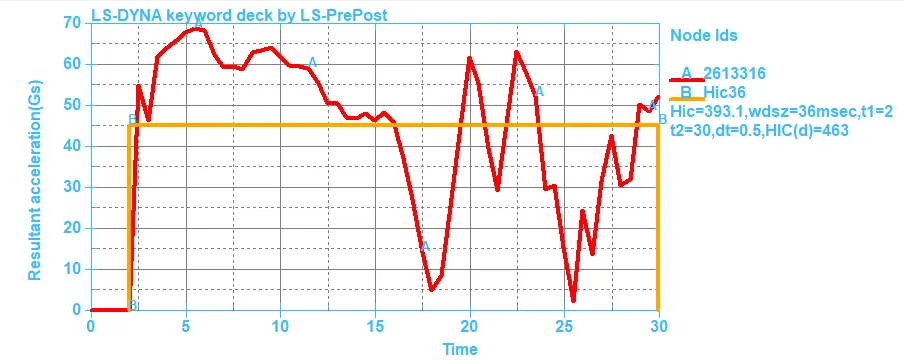
Head injury criteria (HIC):
HIC: 393.1 and HIC(d): 463 Which is less than the Protocol Standard HIC value 650
The HIC-36 value for headfoam impact is measured from an accelerometer place in the geometry. From the graph it can be seen, the resultant acceleration is increased and during the initial impact stage decreased after the 15ms because the hood deforms gradually and slows down the head velocity and it rotates and moves from the contact region.
Conclusion :
- First case: Simple head-model and rigid wall
The simple head-model was defined with MAT_ELASTIC material card which implies the material is pure elastic that’s why the max stress is only there in the time of the impact there is no significant deformation in the simple head geometry. That’s why the HIC values are too high
- Second case: Child head-foam and rigid wall
The standard model of the child head foam with proper material was used, Since the rigidwall is undeformable so the total stress is transferred to the head and deforms the headfoam geometry severely the HIC values are lower than case 1.
- Third case: Child head-foam and bonnet
With The standard head model but in this case, it impacts on the car hood to study the real-life situation the hood was defined with a piecewise linear plasticity material model which is a deformable model so during the impact the hood deforms significantly and reduces stress and strain on the head foam and thus reduces HIC values and the value are lower than case 2