Project - Pedestrian Head Impact Test in LS - DYNA
Week 7 Project 1 - Pedestrian Head Impact Test
Aim
To simulate a head impact test and calculate the HIC.
Explanation
Pedestrian protection CAE is a part of vehicle safety engineering from a crash perspective. In pedestrian protection, we look for imparting minimum injury to head, upper leg (thigh), and lower leg (including knee) in case of an accident with a human subject. These tests are usually done at a lower velocity from 20-40 kmph as accidents tend to result in more severe circumstances above these velocities and braking in case of an accident often results in collision at low velocities.
In this Project a given child head form is impacted on rigid walls and actual hood of a car.
To understand the impact level a parameter called HIC (Head Impact Criterion) is calculated. This formula is derived from observation and data collection from various accidents which happened before.

HIC Quantification
- Small HIC does not mean head injury will of low levels
- Also high HIC means high level injury
- Levels are given by AIS – Abbreviated Injury scale Level 1- 6
- 1 – slight damage to brain – headache , concussion
- 7 – death , cervical fracture to the spine
- Actual meaning is that higher HIC means higher the probability of getting a high level head injury.
- As an example Hic = 650 means 90% probability of level 1, 55 % of 2, 20% of level 3, 5% of level 4
Case 1 – The impact simulation of a simple head impact with the rigid wall.
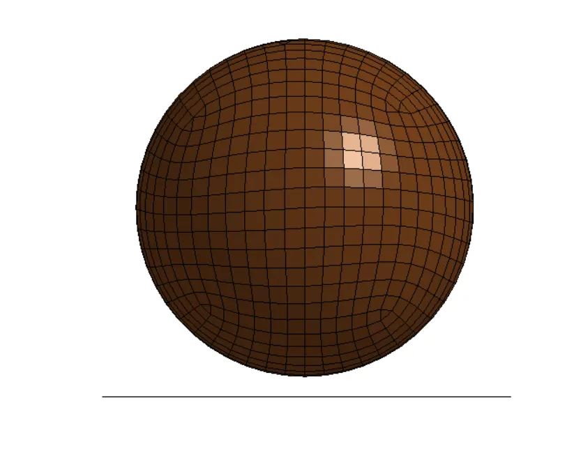
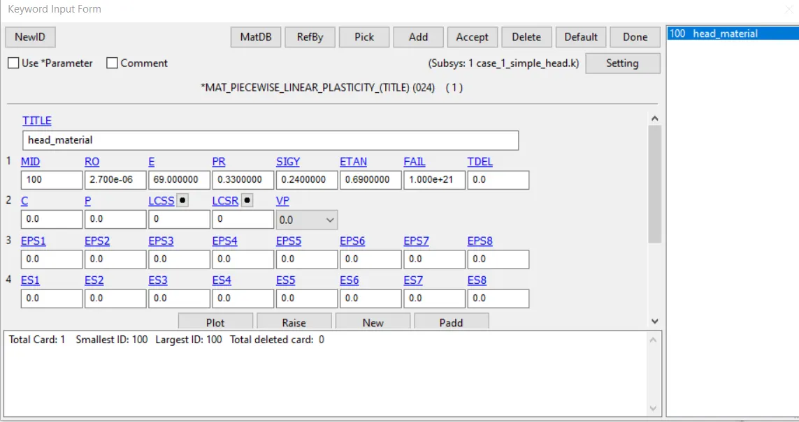
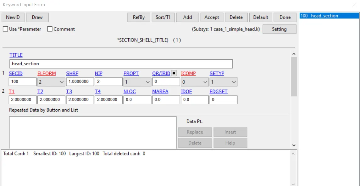
- Assigning the material and shell properties to the sphere, in this case MAT024 is piecewise linear plasticity with aluminium properties assigned. Shell thickness of 2mm and Element formulation 2 is used.
- Planar Rigid wall is created at a distance of 10mm from the bottom of the sphere with the normal facing opposite to the application of the velocity. And slave set sphere is also created.
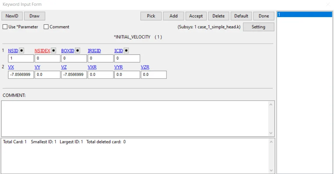
- Initial velocity – Since head impacts at an angle of 45 degree of the hood , the velocity of 40kmph gets divided into 2 components of – 7.8566 mm/ms (horizontal and vertical component)
- Contact definition – Automatic Single Surface is created with slave as the sphere.
- Control cards – Termination (5ms) and Energy are created.
- Database Cards – ASCII cards – GLSTAT, RCFORC, RWFORC, NODOUT are called; D3plot animation step 0.1ms and history node 68789 for HIC generation.
- Perform a Model check make errors and unwanted warnings are avoided.
- We can notice a max von misses stress of 2.67e-01 GPa can be observed on the sphere.
- Effective Plastic strain of 3.947e-02 value can be observed and also we can see that due to the 2 velocity components we can see the sliding off the sphere as it makes contacts with rigid plane.
- HIC = 7.11e06 for a time period between 2.2ms to 4.24ms.
Case 2 - The impact simulation of the Head form provided with the rigid wall
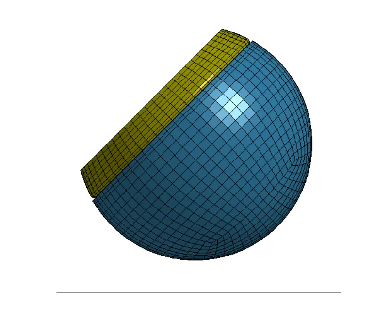
- In this case sphere is replaced by the given child head form which contains 4 parts which are Skull, back plate, accel block and skin. The material data of these parts are given below.
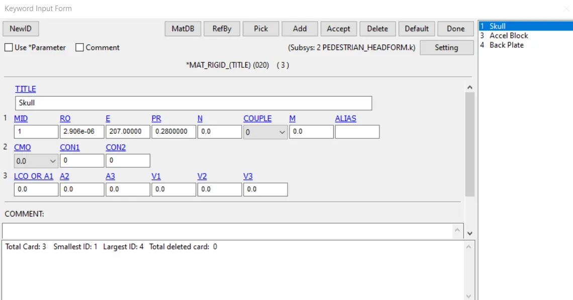
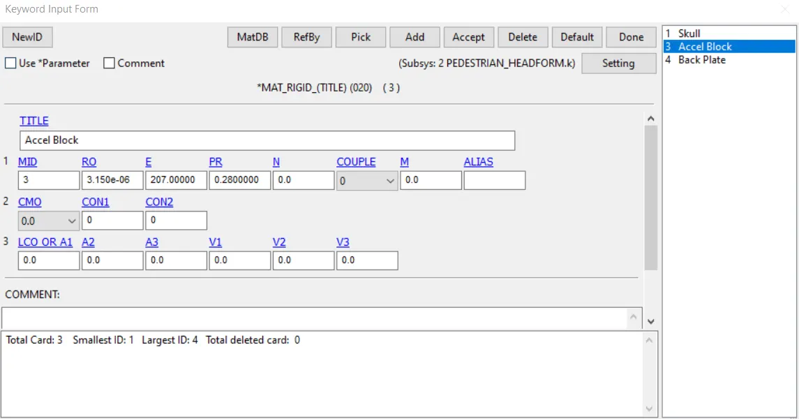
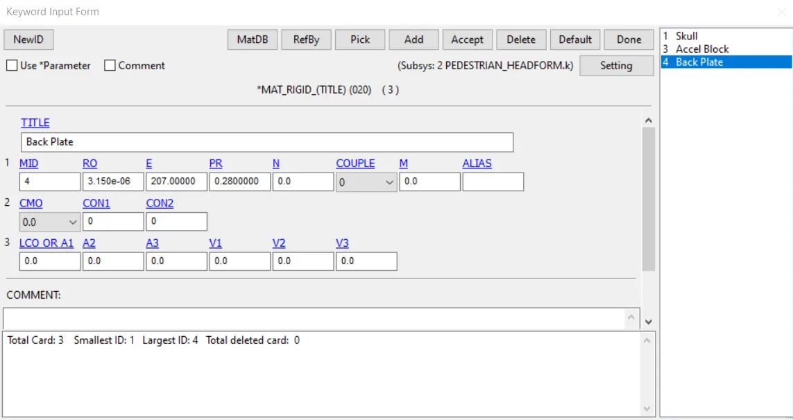
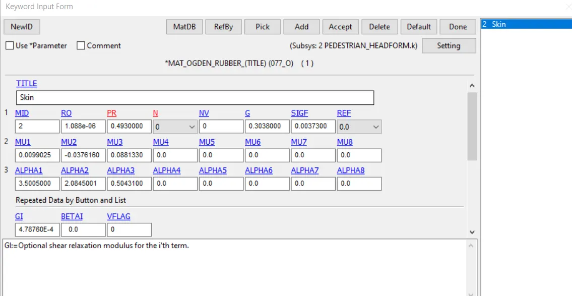
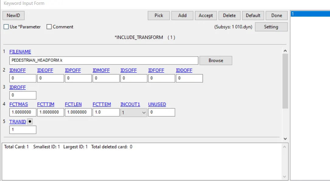
- Include Transform card is used to call the head form into the main file
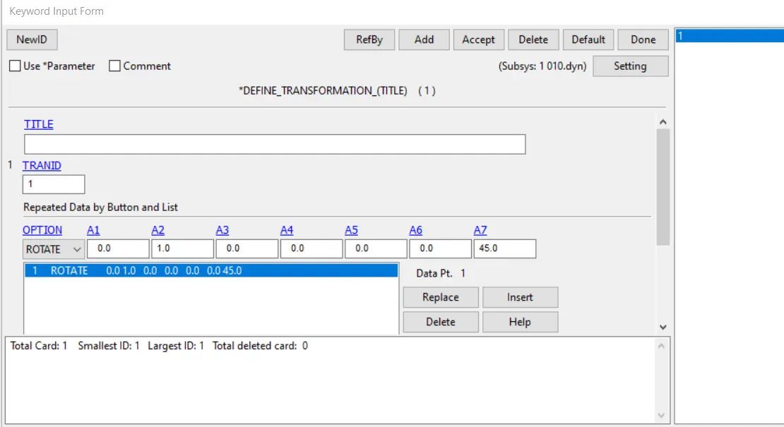
- Define Transformation is used to rotate the Pedestrian file and direction cosine is given in y axis and rotation of 45 degree is given.
- Initial velocity is given to the head form in the same way as in case 1.
- Contact cards – Skull is given automatic single surface contact; Skull and skin is given surface to surface contact between them with skull as master.
- Database and control cards are called similar to case 1.
- Need to make sure that the new main has to be saved separately.
- We can notice a max von misses stress of 1.143e-02 GPa can be observed on the sphere.
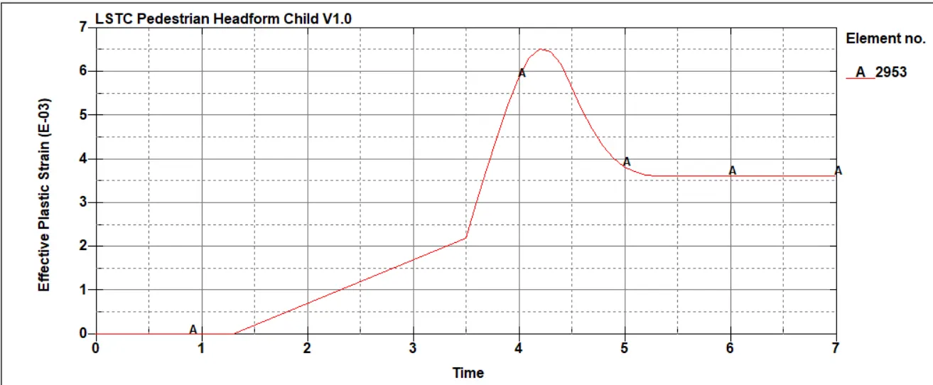
- Effective Plastic strain of 6.540e-03 value can be observed
- HIC = 2.564e04 for a time period 3.55ms to 4.5ms. (Seat belt accelerometer is used to obtain the HIC)
Case 3 - The impact simulation of the head form with the Hood
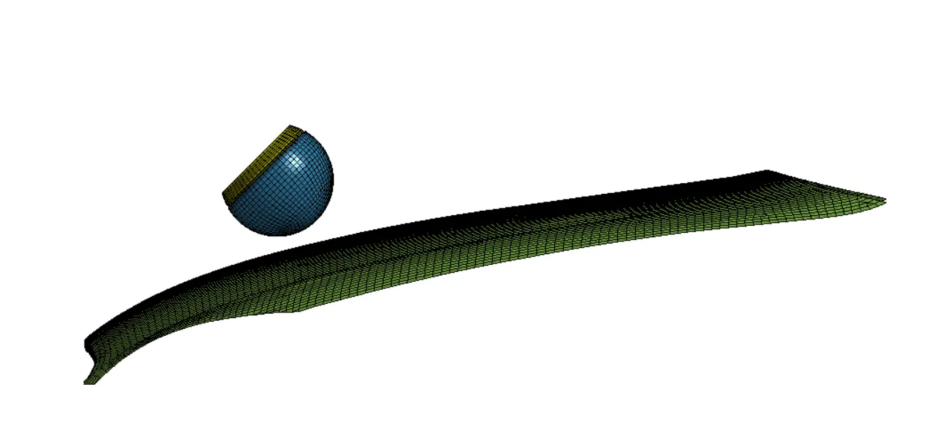
- In this case the rigid wall is replaced by an actual hood and head form is impacted on it.
- Include the hood file in to main file using Include card, and Include transform for calling the head form and define transform to rotate the head form to 45 degrees ( similar to case 2)
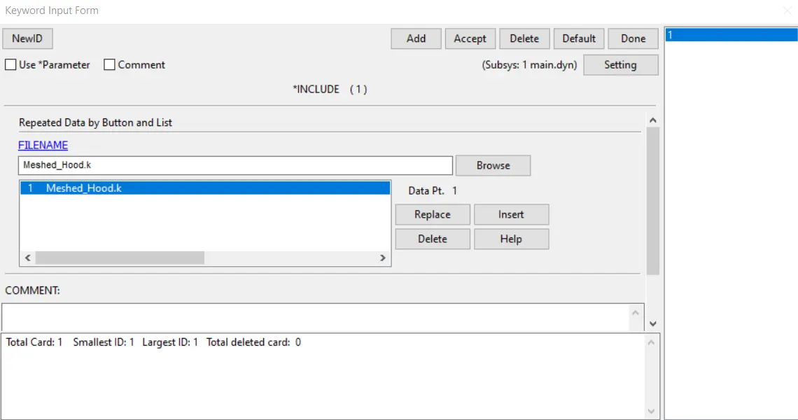
- For the hood Aluminium material card is used.( MAT024 Linear Piecewise Plasticity )
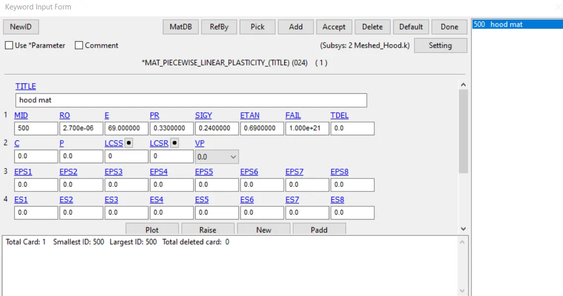
- Initial velocity is given to the head form in the same way as in case 1.
- Contact automatic surface to surface is given between the hood and the head form.
- Database and control cards are called similar to case 1.
- HIC = 300.7 for a time period 2.18ms to 14.1ms. (Seat belt accelerometer is used to obtain the HIC)
Results and Comparison
Case 1 :
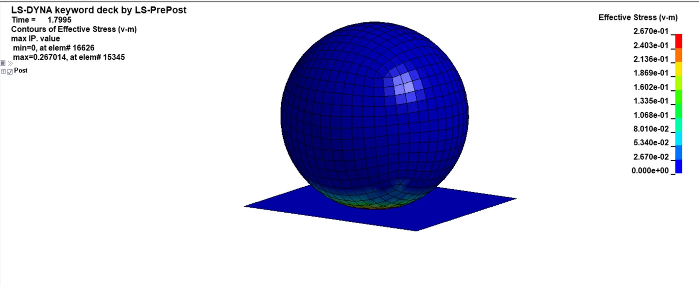
As the sphere impacts the rigid wall the we can observe the material undergoing deformation. (for the case 1 the sphere is material is made of Aluminium). Once the material reaches yield stress (0.24) point we can observe plastic deformation in the sphere.
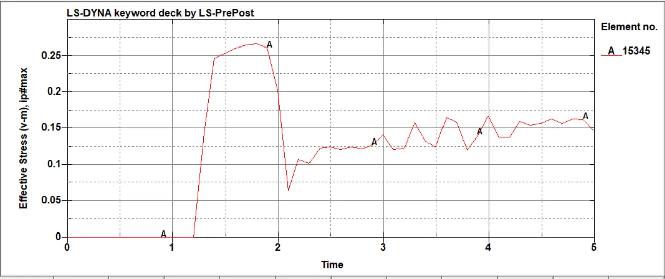
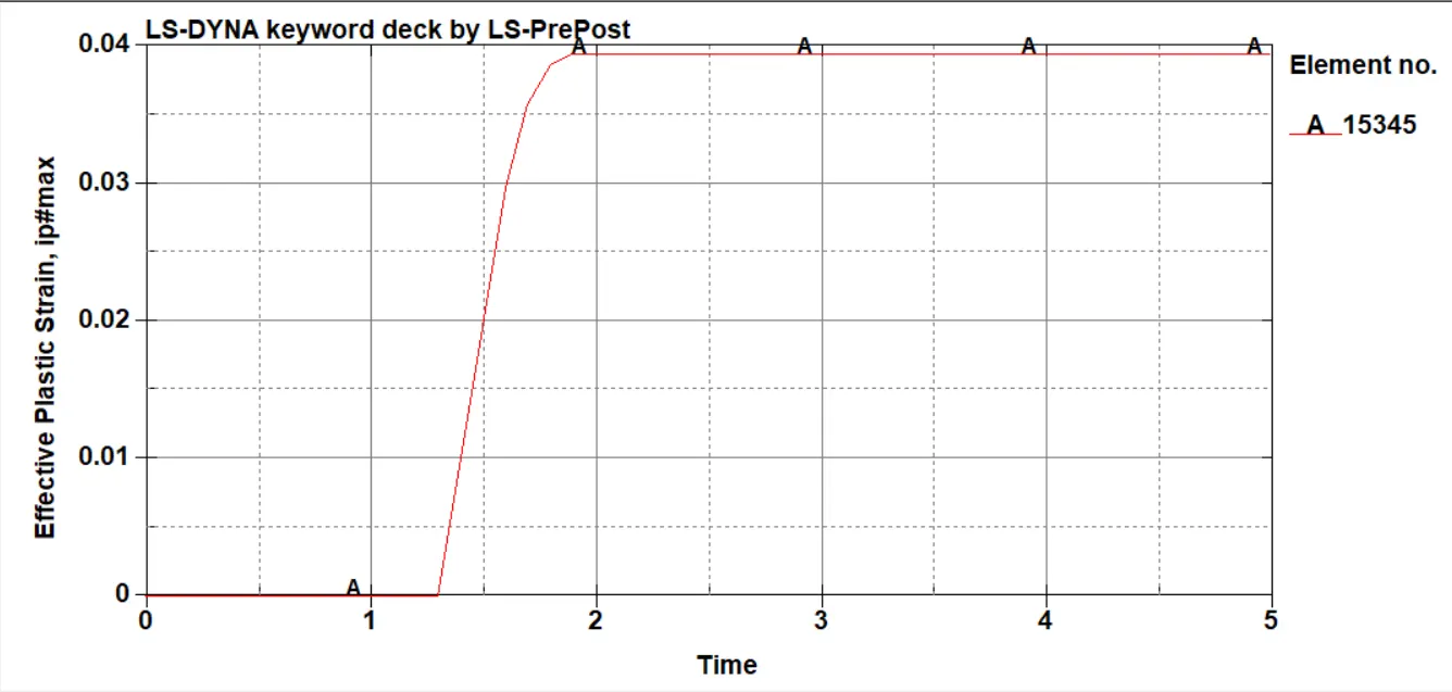
Strain reaches value of almost 0.04 , material reaches its plastic region and it remains constant for the rest of the time as the sphere bounces of the rigid wall.
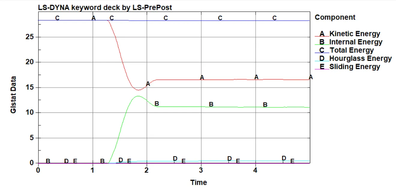
Kinetic energy is maximum as the sphere approaches the rigidwall with a initial velocity and as it impacts we can see the drop in kinetic energy and the rise in internal energy.
Hourglass energy is kept under the control of less than 5% of the total energy , hence the analysis is stable.
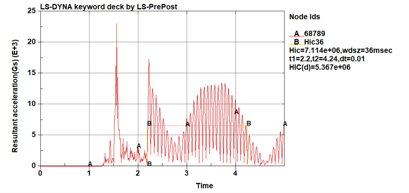
HIC for the impact of the sphere on the rigid wall is 7.11e+06 , which very high value , this is due impact on the rigid wall.
Case 1 gives a general idea of the deck setop for the case 2 and case 3 where actual headform is used to measure the HIC.
Case 2
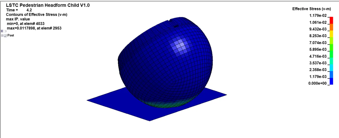
We can observe the headform undergoing plastic deformation , most of the stress is getting the absorbed by the skin part of the head form.
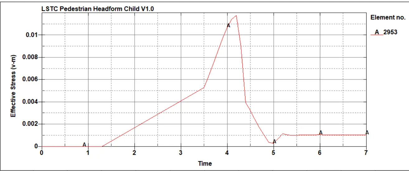
As the headform bounces of the rigid wall the stress and strain levels drops to reach a contant value and its the permanent deformation caused by the impact.
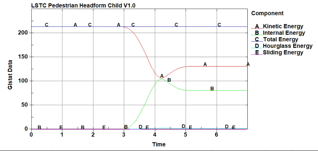
The Kinetic energy can be seen droping after the impact as the internal energy due to the strains rises up. Hourglass energy is well under the control.
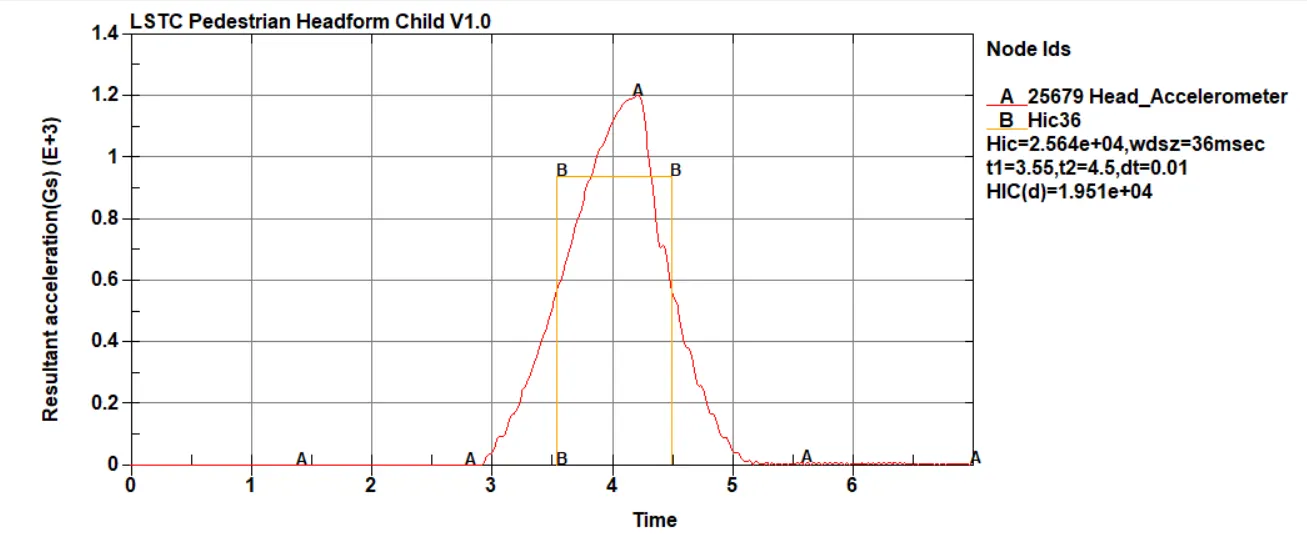
HIC value of 2.564e+04 is achieved for this case 2 impact on the rigid wall. This value is also comparatively large due to impact of the headform on the rigid wall.
Case 3
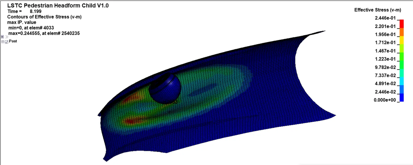
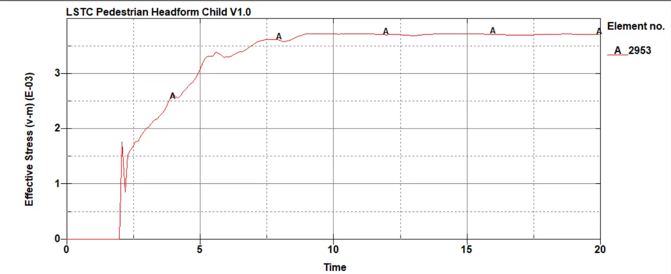
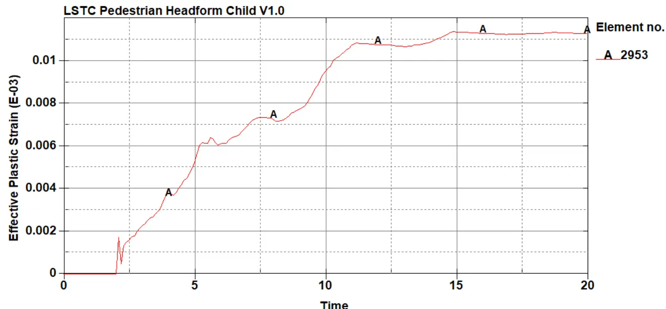
In this case the headform is undergoes lesser magnitude of stress and strain compared to case 2 as the hood is absorbs the energy (deforms).
From the safety of the pedestrain this is good as it prevents HIC reaching a higher value.
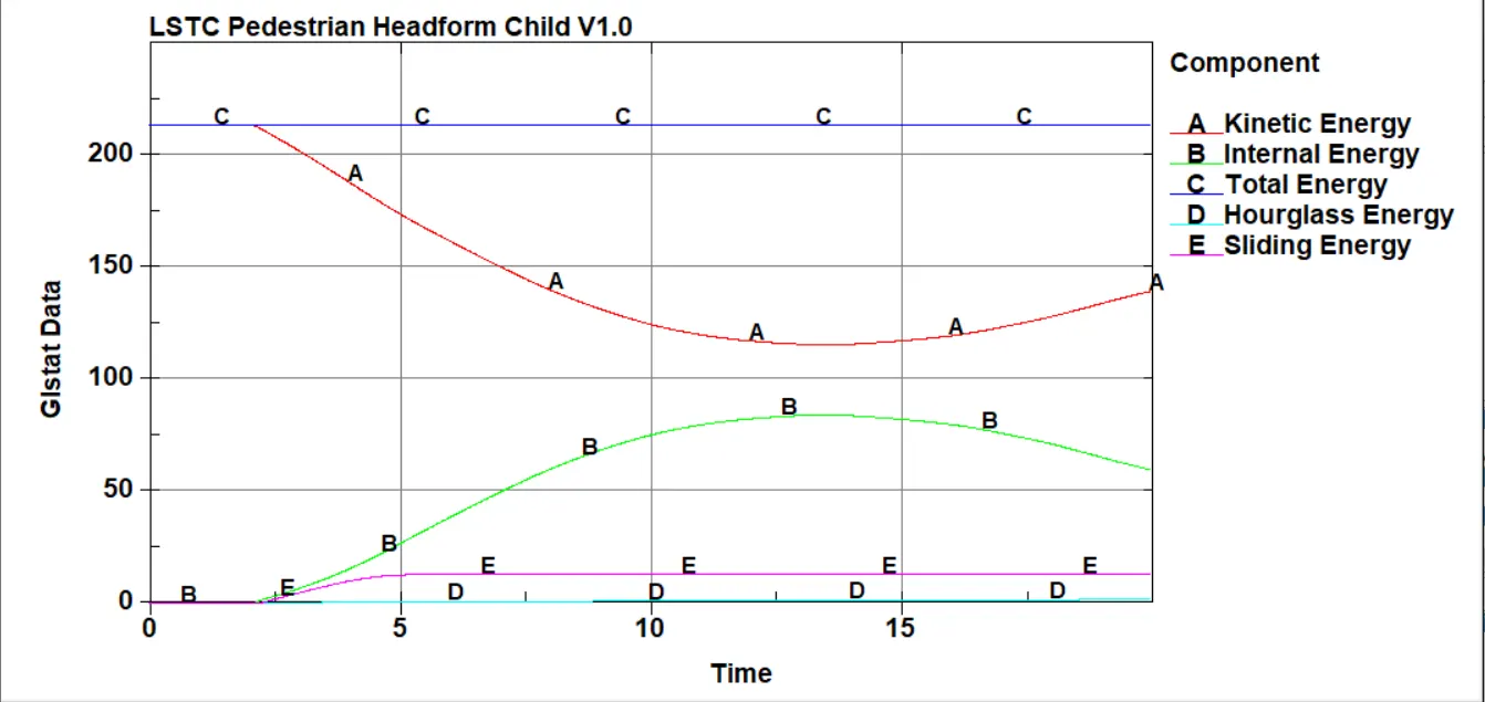
The global energies , including the hourglass energy are under control meeting the required criteria
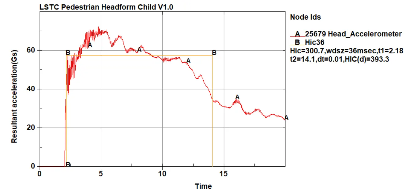
The HIC value of 300.7 is very less then case 1 and 2. This means lesser probability getting a higher level head injury.
Conclusion
- For this project , using of include and define transforms cards was used to rotate the headform to the required orientation.
- Main files was used to call the headform file for this simulation.
- HIC values obtained can be used for the application of helmet design , active hood designs for the safety of the pedestrain.
- There is a drastic difference between the cases in terms of the HIC values , from the point of the manufacturing a hood - thickness and materials ability to deform plays a very important role in safety.
- Kindly rerun the main dyn for the output files. ( Due to upload constraint of 200Mb)