Week-7 Head Impact
Pedestrian Head impact Analysis according to Euro NCAP regulations: EC 78/2009
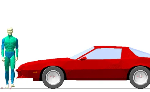
Objective: To study pedestrian head impact by simulating it using a given child headform model for the impact analysis as per Euro NCAP standards for impact velocity and positioning of the headform model as well as the hood model to get as realistic results as possible.
Analysis Setup:
Pedestrian Head Impact analysis:
In crash safety domain, along with crashworthiness, and occupant safety, pedestrian safety plays a major role of the regulations. The regulations make sure in case of an accident with a pedestrian, all the components that will make some contact are flexible and absorb as much of the kinetic energy as possible to reduce the severity of the injuries.
Head being the most sensitive part of a human body, needs the most protection in terms of any crash or accident for that matter. Head injuries comprise of 70% of the fatal pedestrian accidents according to the euro NCAP. Making the component which comes in contact with the head in pedestrian accidents – the hood, more compliant makes a significant difference. But it compromises the ‘crashworthiness’ part of the safety domain in case of full frontal impact. As a result it is a compromise and the OEMs work hard to make the vehicle compliant to regulation for both the cases.
The given headform model is made to have an impact with a stationary obstacle in ideal case a complete model of a hood with inner panel and all its details, and the results of this impact more importantly on the headform are studied, with stresses and HIC values being the major concerns.
In our case, we first use a rigid wall instead of the hood model which is a simpler alternative of the test. The results in this case are expected to be much higher and hence unsafe as the ‘Rigid’ wall will not absorb any of the kinetic energy and the headform will experience a lot of stresses and deceleration. This will be a good benchmark to test the hood model and its design.
To keep things simple the given hood model is just an outer panel so the results won’t be very realistic. A good material model and an approximate section thickness should give something to work with.
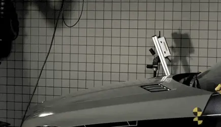
Analysis setup:
For the Euro NCAP regulation, a standard model headform each for an adult and a child is made to hit the hood of the vehicle along with all the components in the area – the engine, intake and exhaust system, electronics etc. to make sure even if the hood panels are compliant, if there is not enough room between the hood and the components, the results will be realistic when such an accidents occurs in real life. ‘WAD’ or the ‘wrap around distance’ is the peripheral distance from the ground the head of the pedestrian will cover, when wrapped around the front end of the vehicle in case of a crash.
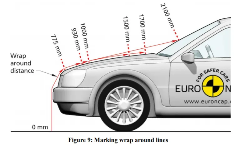
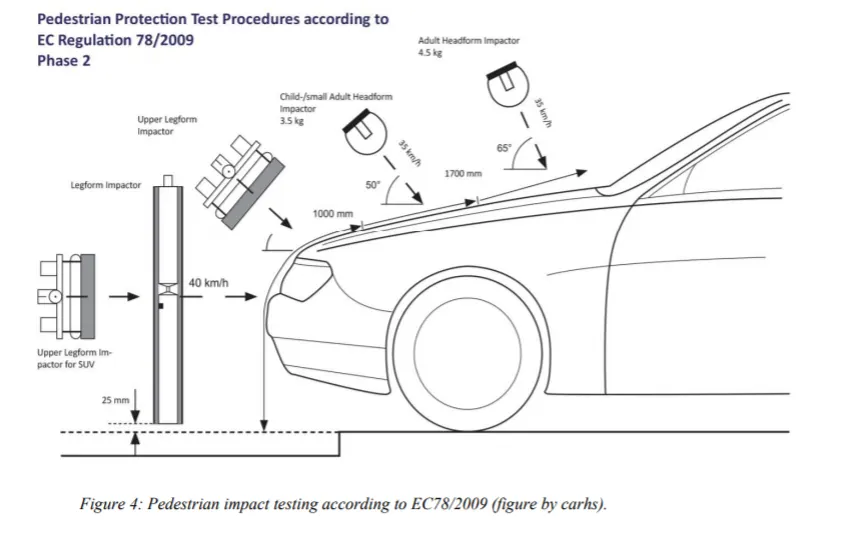
For the child headform, the regulations suggest a WAD of 1000-1400mm. In our case, the height of the hood from the ground is unknown, so we take the hood front and rear edges as reference. 360mm from the front edge is the impact point approximately. Now for the positioning and impact velocity, we follow the regulation with the headform tilted at 50 degrees with the vertical and approaching at 35km/hr.
The acceleration or deceleration which is often the reason behind fatal head injuries is calculated using Head injury criterion or HIC. If for a given vehicle, in a regulated head impact test, the HIC figures are within a certain range, the vehicle is given rating points which basically tell how safe the vehicle is in such a crash and how likely a pedestrian is going to survive it without any serious injuries.
`HIC=max_(t1,t2){[ 1/((t2-t1))*∫_(t1)^(t2) a(t)*dt]^(2.5)*(t2-t1)}`
where ‘a’ is the resultant acceleration over time ‘t1 to t2’.
As the headform and hood models are standard models and are not supposed to be altered in any way, specially geometrically, we use the ‘Include_Transform’ keyword to ‘include’ these models as a subsystem of the analysis. Using the ‘Transformation’ card, in ‘define’ keyword, the orientation, scale and position of the model is altered to fit the given case.
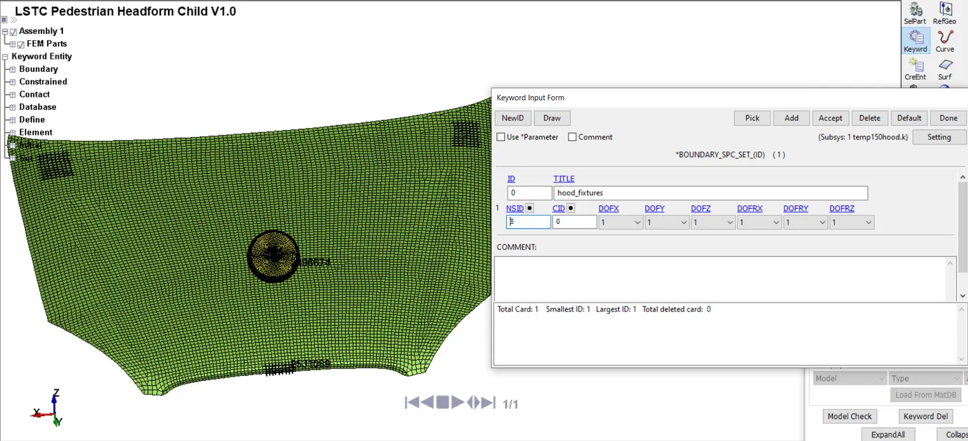
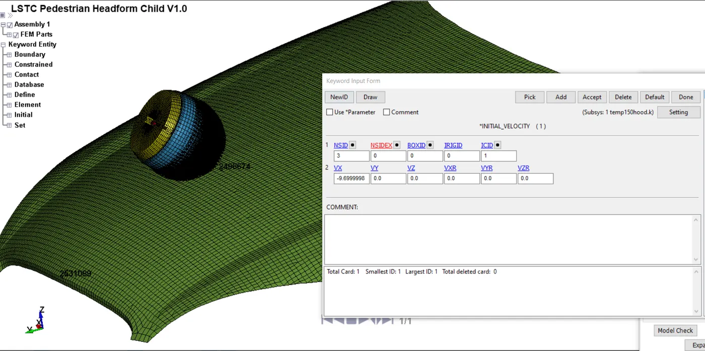
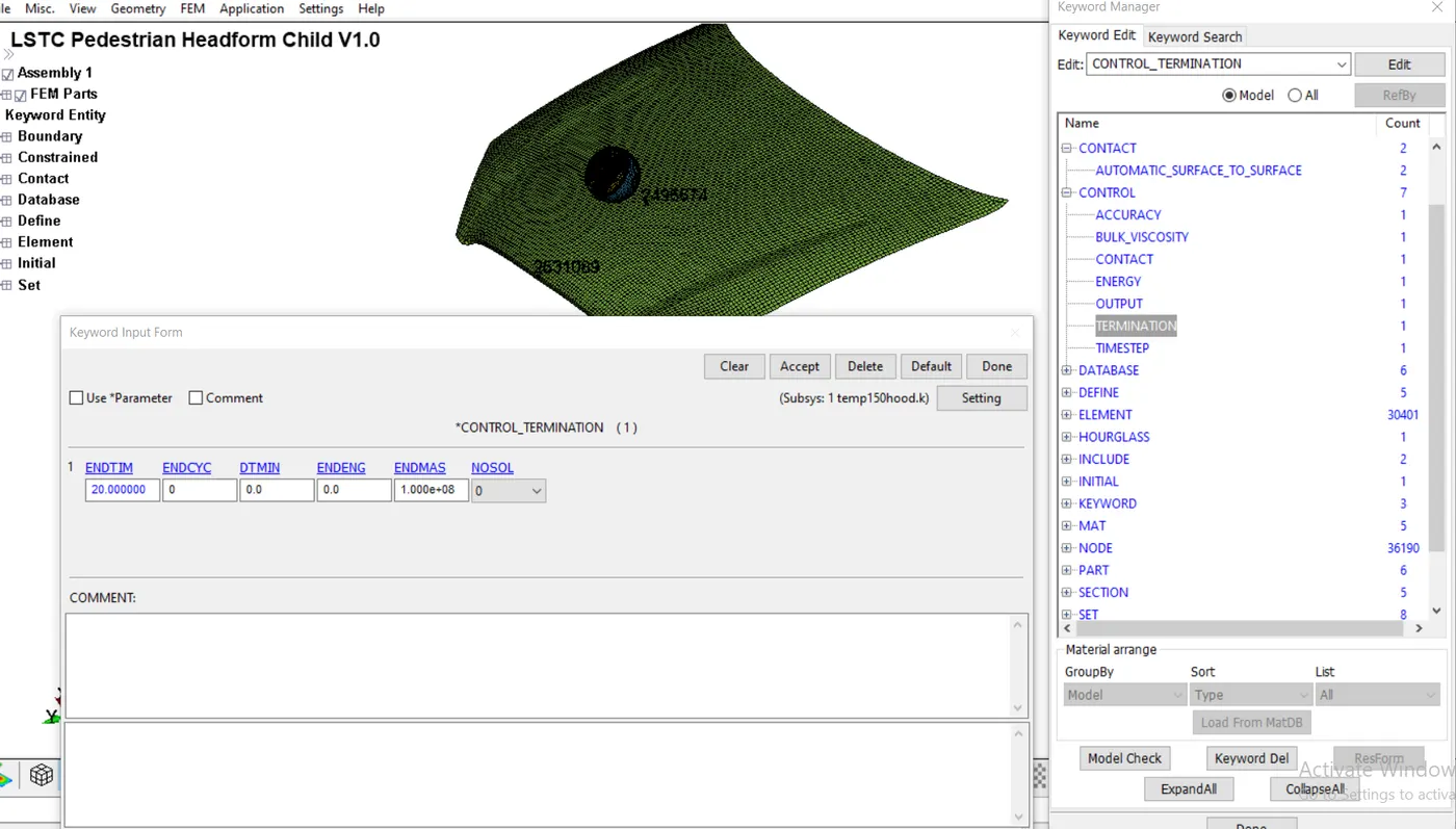
Using a ‘set’ of all the nodes on the headform model, and adding the set to an ‘Initial velocity’ card, we provide the impact velocity for the simulation. To keep things realistic, a set of nodes at the front hood lock, and the rear supports was given a 6 DOF constraint such that the hood deflects only in the middle. Other than this all the general output requests and accuracy setups were added to the system and a termination time of 20ms was given. The unit system was maintained in [kg mm ms] system.
As an added exercise, the simulation for adult pedestrian impact was done as well using the given headform only. To start off easy, the analysis was done with a rigid wall in place of the hood as mentioned before for benchmarking purpose.
Procedure:
- PART, SECTION, MAT definition:
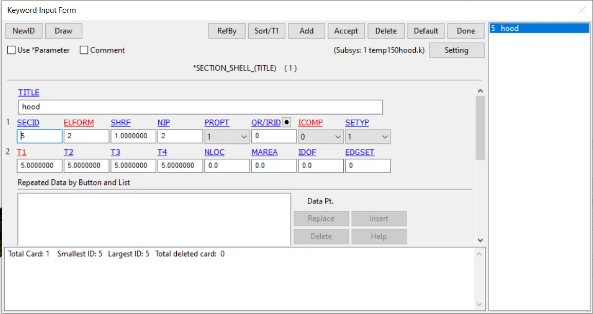
To get comparable results, the section thickness of the hood was kept 5mm . All other predefined parameters were kept the same as their systems.
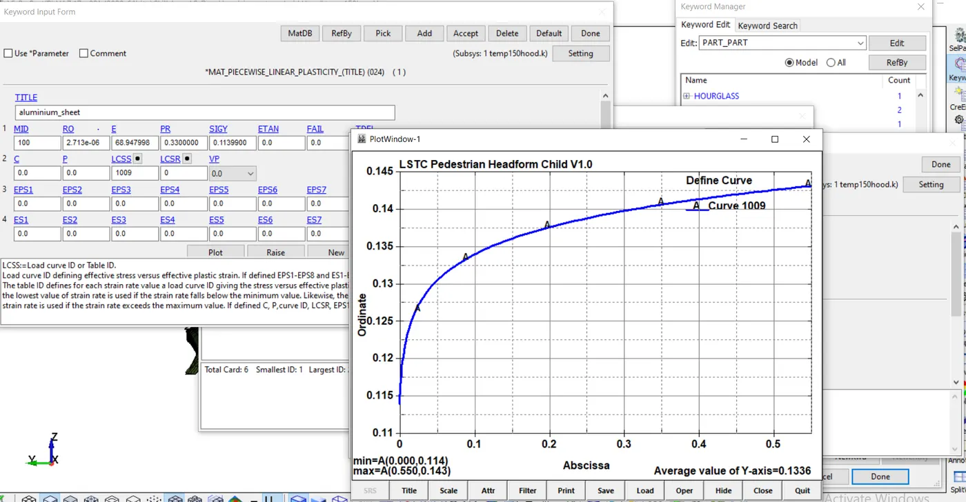
As suggested for the hood, Aluminium sheet 14 material properties were used with MAT24 linear piecewise plastic material card. An effective stress strain plot was defined for more accurate results.
The material properties were taken from the following source:
https://www.varmintal.com/mat24-all.zip
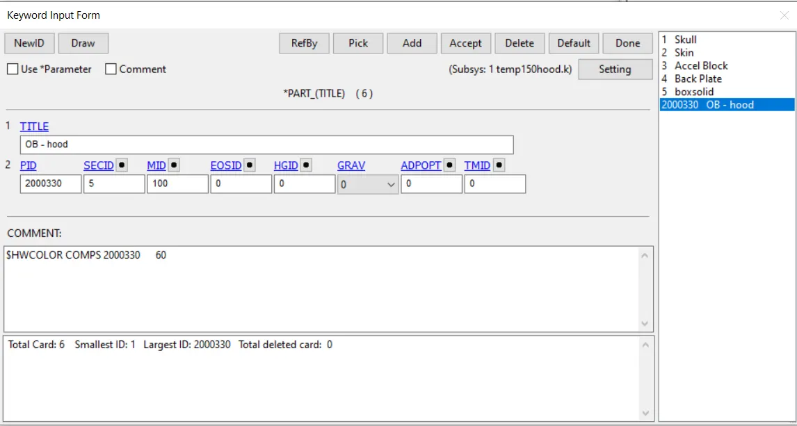
In case of the rigid wall analysis, all the part properties and parameters were left as they were.
- Boundary conditions and Rigid-wall definition:
As mentioned above the only boundary conditions defined were the SPCs and the initial velocity given to the headform, which were straightforward.
After converting the velocity to given unit system, it comes out to be 9.69 mm/ms. Using the local co-ordinates system which was present in the subsystem, the velocity was given such that the impact would occur at an angle as given in the regulation.
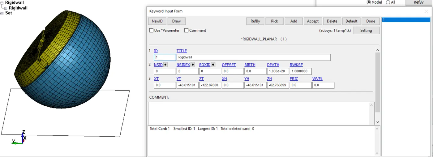
For the 1st case, the rigid wall was set up as close as possible to maximise the simulation time.
- Contact definition:
A general surface to surface contact with element segment sets from both the hood and the skin part from the headform was setup with the hood set being the master and the headform being the slave component.
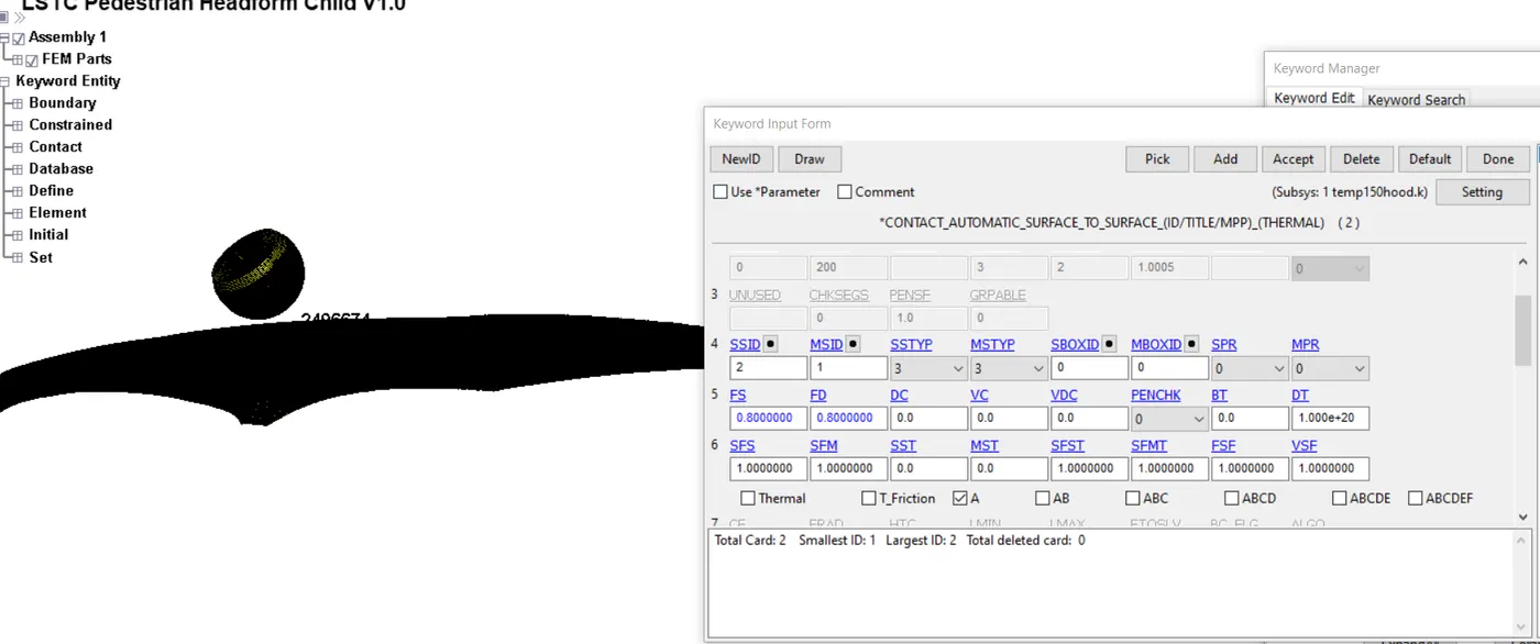
As mentioned above all other settings and keywords necessary of any analysis were added and the simulation was initiated.
Results:
CASE 1:
Rigid wall Impact:
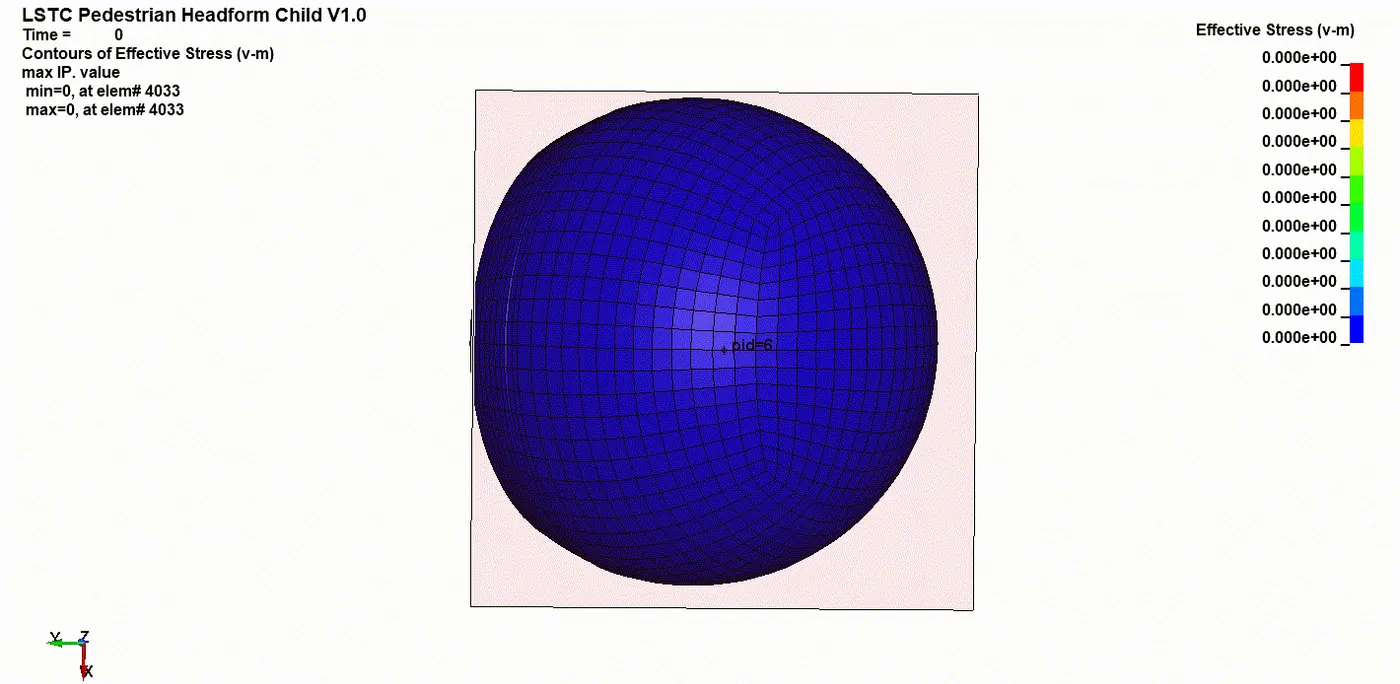
Stress and strains:
As expected, the stresses and strains are very high since the rigid wall provides no cushioning.
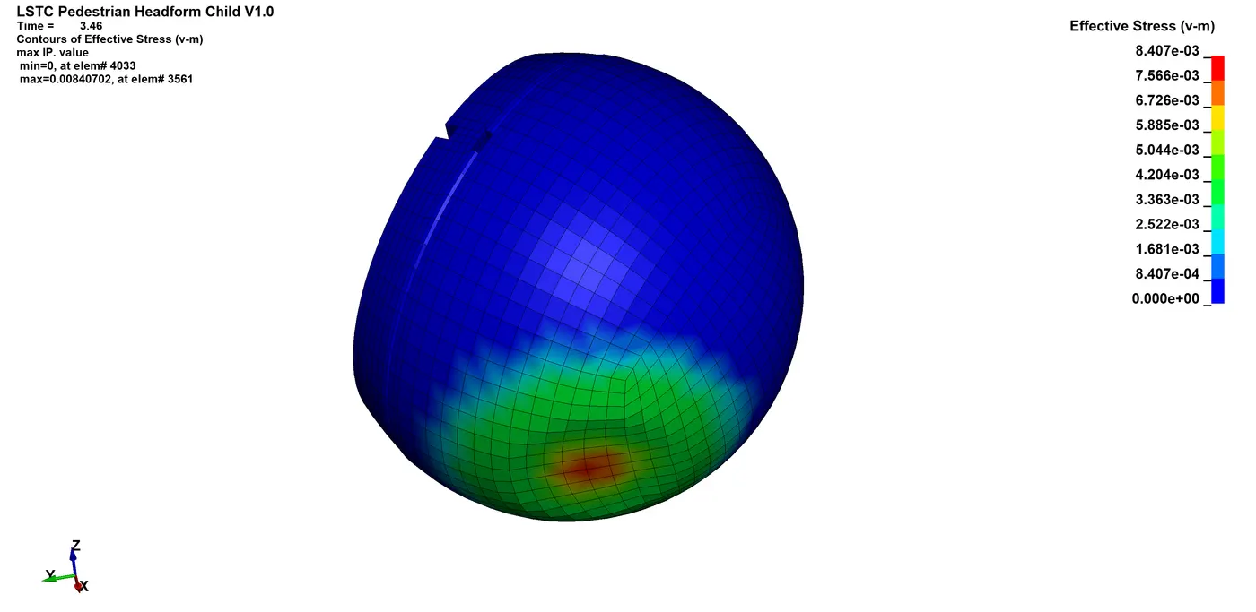
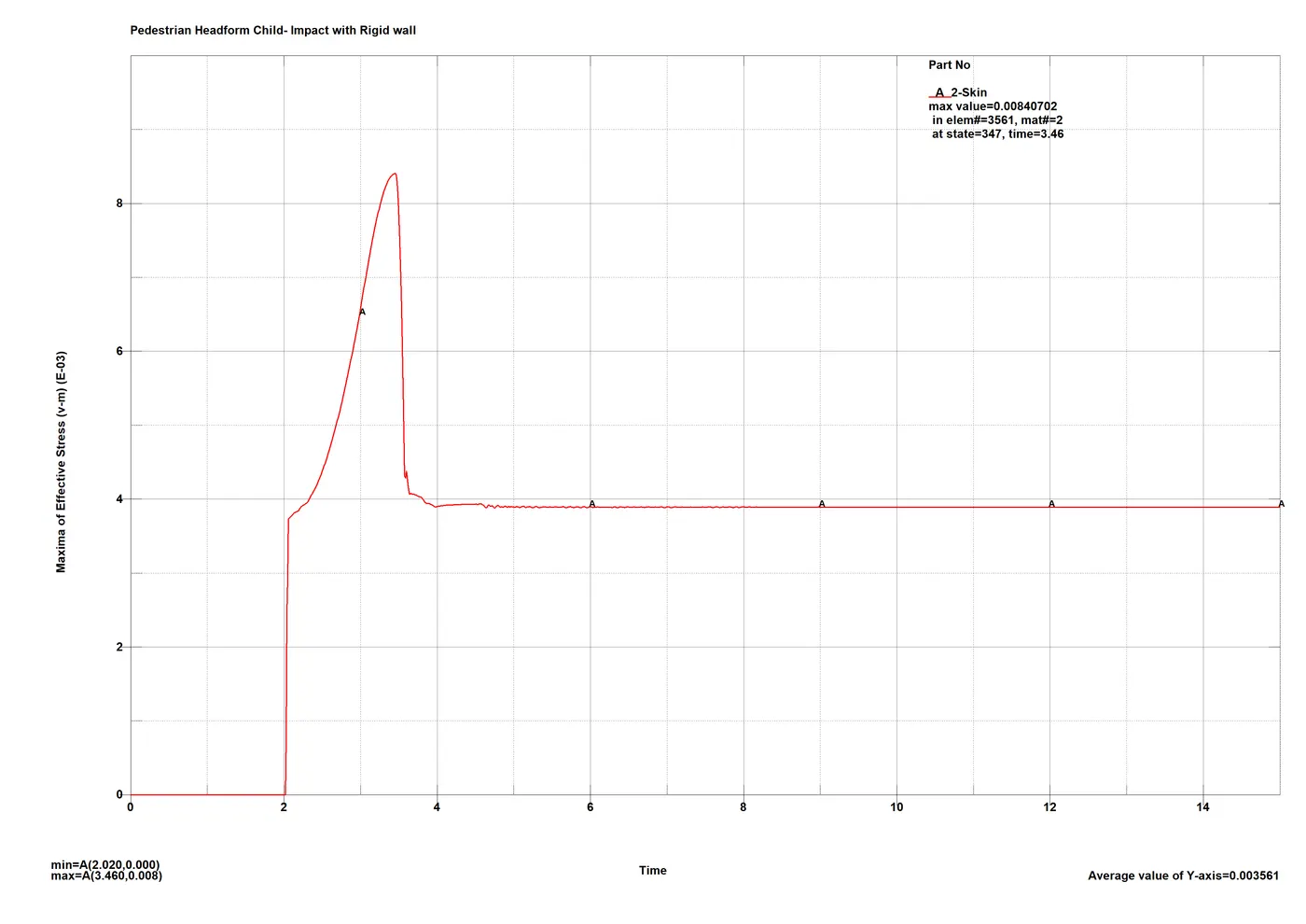
A peak stress of 8.407MPa at the contact point which settles down to about 3.8MPa is recorded. Although the value is very high, the peak lasts about 0.5ms which is not much as a result, the HIC values are more important in such cases.
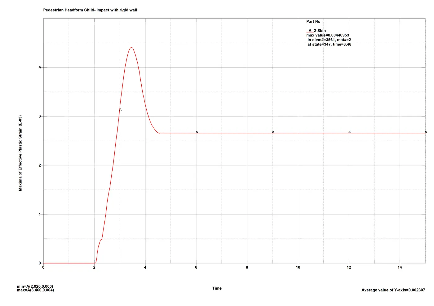
A plastic strain value of 4.4e-3 was recorded at the impact position with permanent deformation of about 2.6e-3 or 0.26%.
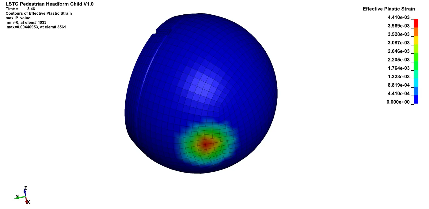
Permanent deformation is apparent from the plastic strain plot.
Energy plot:
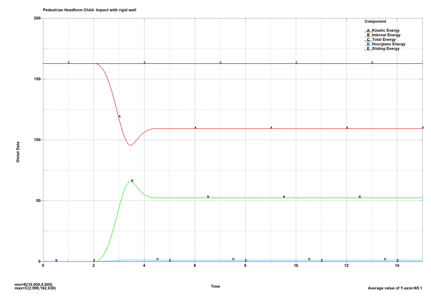
From the plot it can be seen that there is minimal hourglassing in the analysis, and hence the results are dependable. The K.E. and I.E. plots never cross as there isn’t any deformation on the rigid wall side, elastic deformation on the headform is indicated by the bump and the intercept after the bump indicates the permanent deformation.
Acceleration plots:
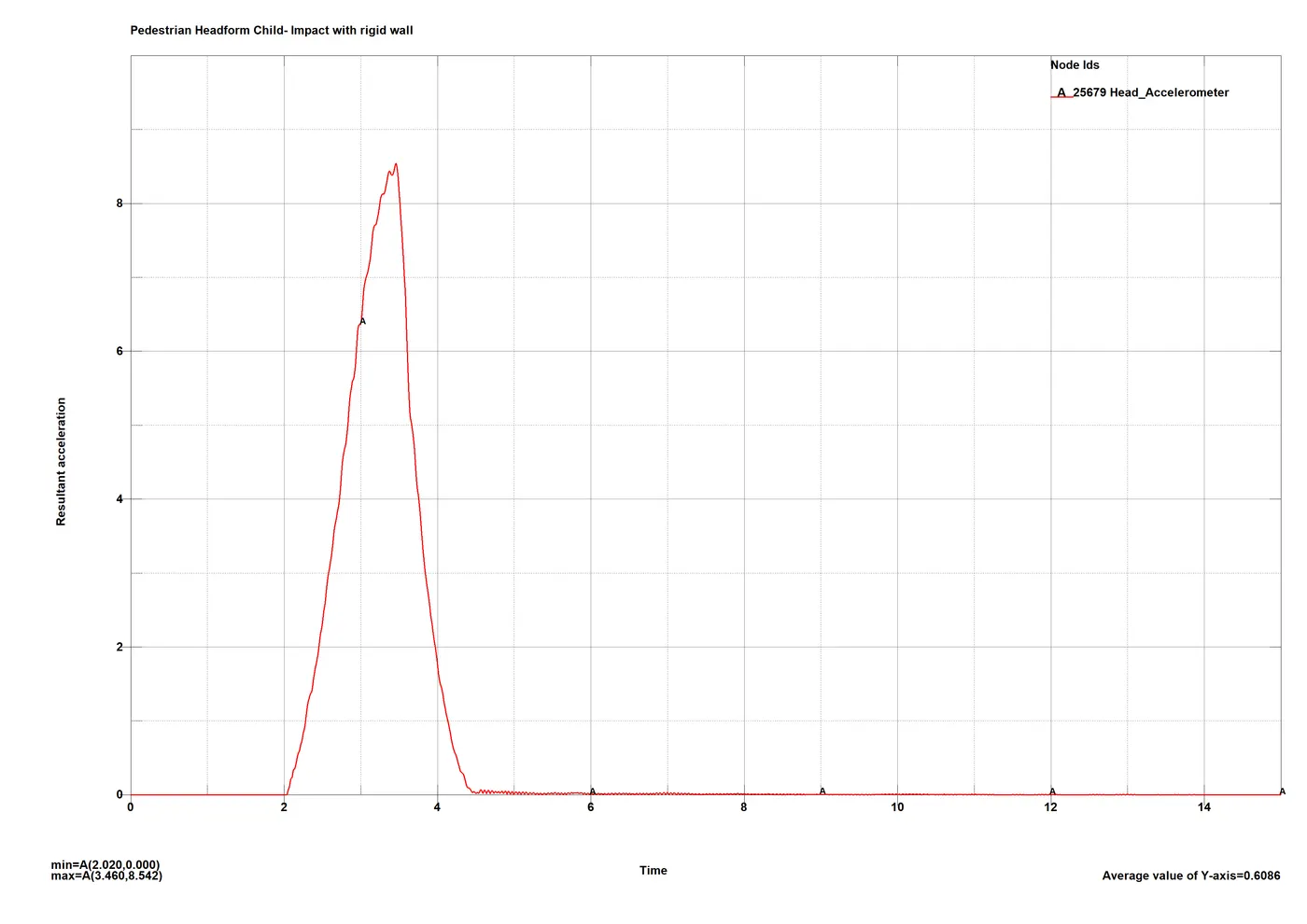
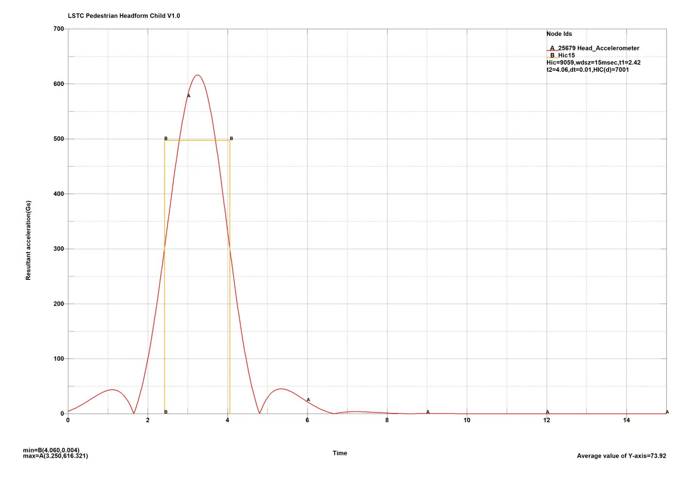
A peak resultant acceleration figure of 8.542 mm/ms2 at the time of impact shows the severity of the crash in this case.
A HIC3 figure that is the head injury criterion for a 3 millisecond window of 9059 which is absurdly high and way over the considerable range is recorded which is expected with a rigid wall impact in any crash.
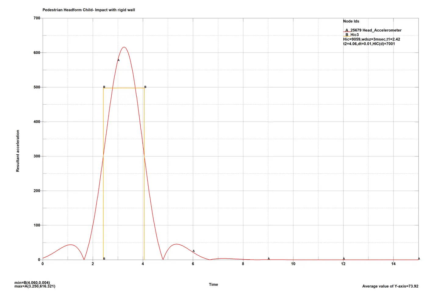
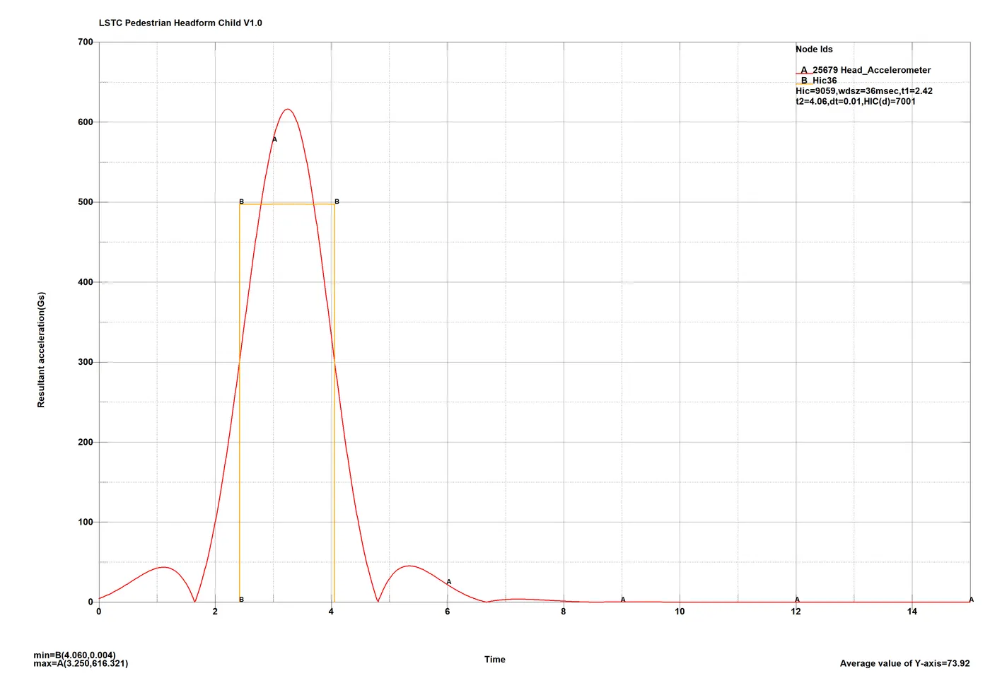
As per the regulations for any resultant acceleration figure and as a result any HIC figure to be considerable, the peak figure should last for at least a window of 3ms. As seen in the plot above the peak hardly lasts 3ms, hence the HIC15 and HIC36 plots would be redundant and so will be their outputs.
HIC36:
CASE 2: Child Pedestrian impact regulation, impact with hood model with 5mm thickness:
Stress and strains:
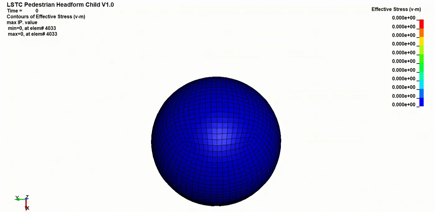
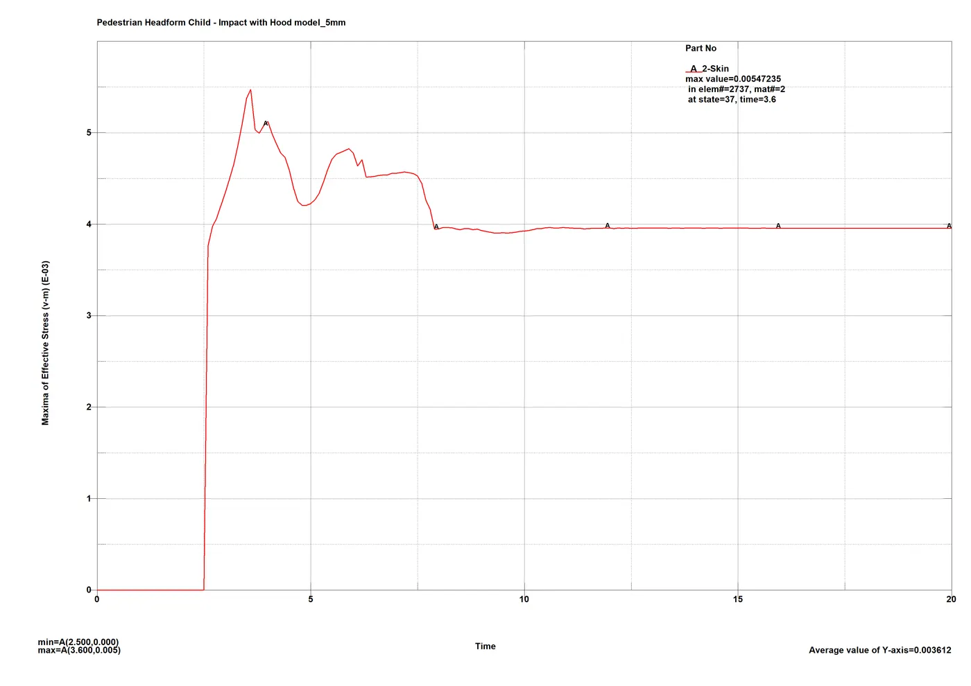
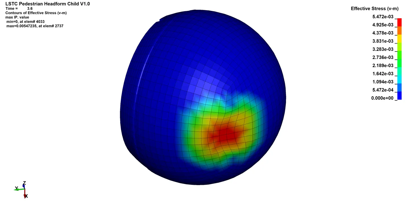
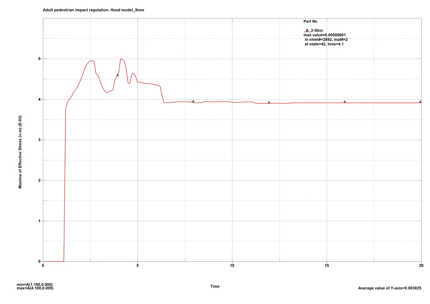
A considerably low peak of 5.472MPa is registered as the hood panel deforms on impact, absorbing some of the K.E. After the impact, when the headform rolls out and bounces off the hood a constant 3.9MPa stress is recorded.
As expected, the impact point area gets stress concentration and only a small portion of it is distributed over the face.
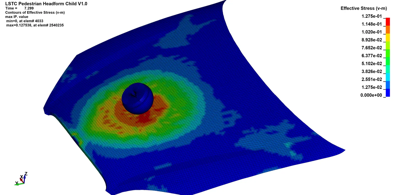
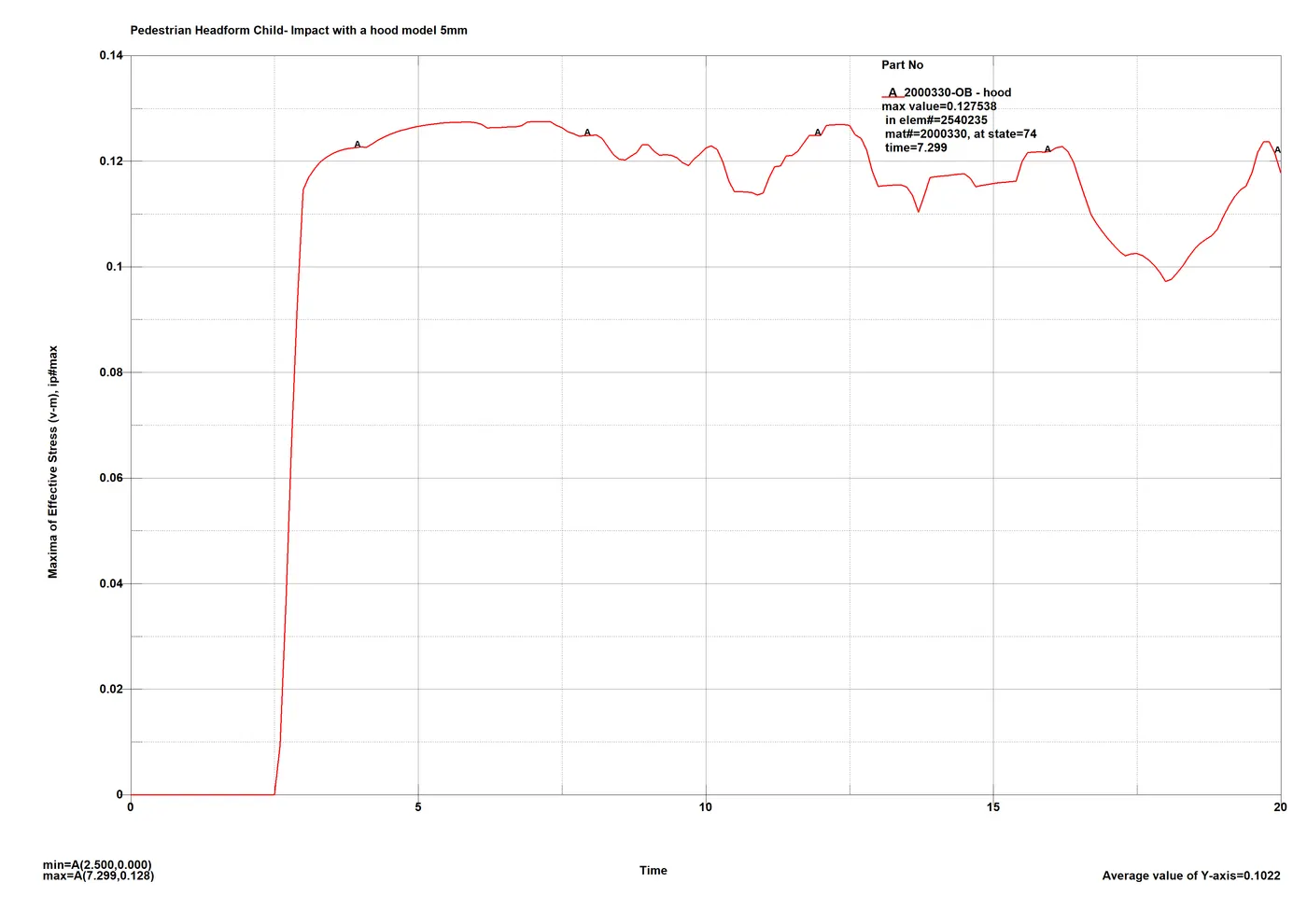
The hood model being the less stiff of the two, absorbs a lot of the impact K.E. and gets peak stress of 0.1275GPa or 127.5MPa. This is within limits for the component.
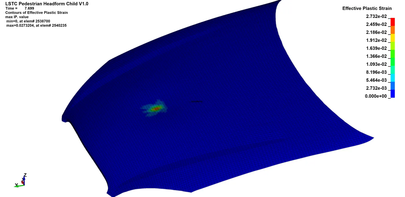
Plastic strain of around 2.732% around the point of impact is seen where the stresses overcome the elastic limit.
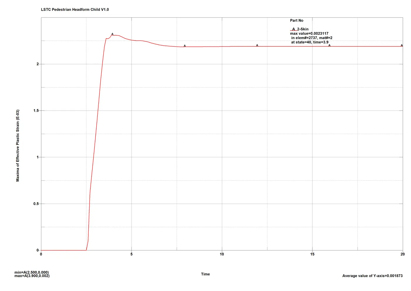
On the headform however, almost half the strain is registered, around 0.2312%. The area of concentration is very small as well indicating small contact area at the impact.
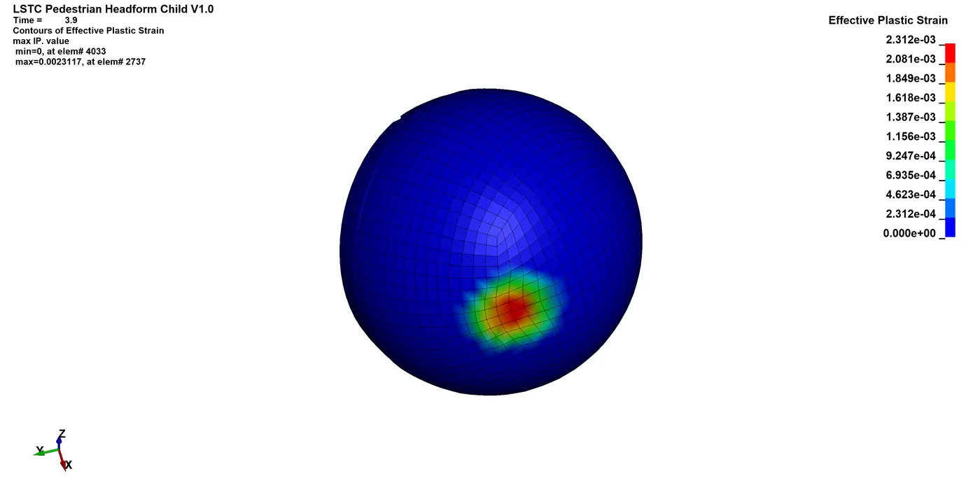
The peak settles down to 0.2311% which is the permanent deformation on the headform.
Energy plot:
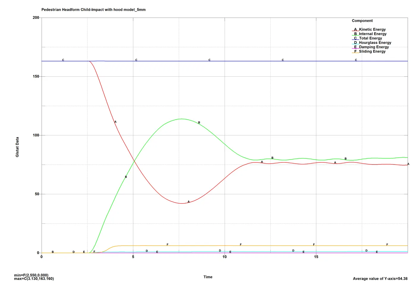
Similar to case 1, the bump indicates elastic deformation of both the headform and the hood model, and the settled intercept indicated permanent deformation. Contrary to case 1, the plots for K.E. and I.E. cross each other as there is enough deformation which causes conversion of K.E. into I.E. in the simulation. As the headform bounces off, the K.E. of the system is regained just as the elastically deformed components get back in their original dimensions and the system goes on to stabilize.
Acceleration plots:
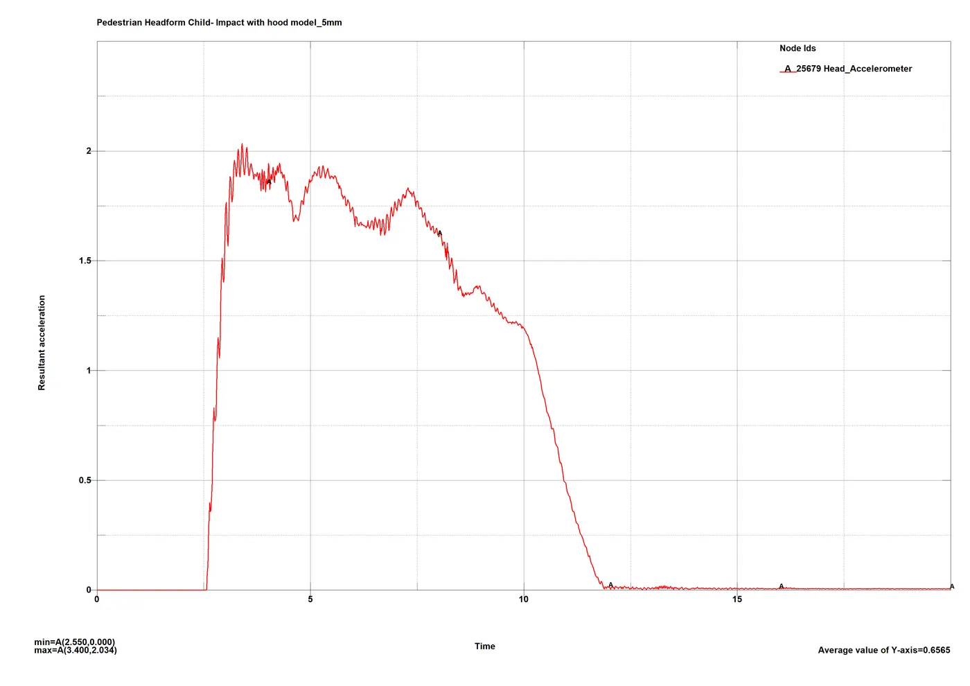
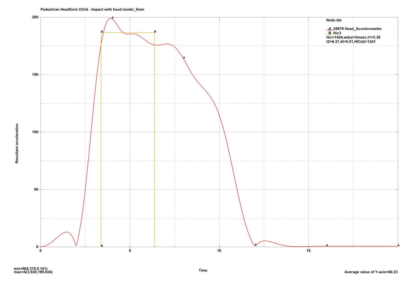
A lot more noise is seen in the plot compared to case 1 courtesy of the deformation of the hood. Compared to case 1 almost 1/4th the peak acceleration is recorded form the headform accelerometer. The peaks last longer in this case so the HIC3 figure is considerable.
HIC3:
HIC3 figure of 1424 which as per the regulations is very high but is within regulatory range is recorded. Due to the inaccuracy of the models of both headform and hood, it is understandable and compared to case 1 the value is significantly lower which proves the point.
The result is according to the Euro NCAP test, in orange zone with limit of max HIC <=1400 which should give the hood model a satisfactory rating and second highest points for the test.
HIC15:
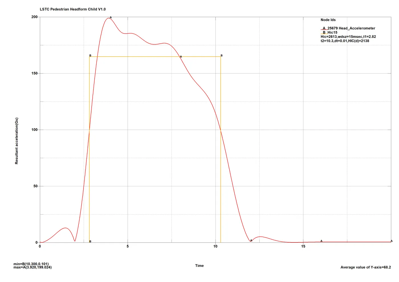
As mentioned, the peaks of the plot don’t last that long for both HIC15 and HIC36 to be considerable, but as expected the figures are significantly lower than case 1.
HIC36:
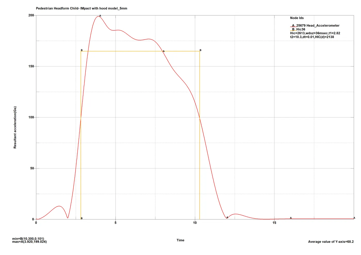
As stated earlier, the peaks don’t last long enough as a result inaccurate and redundant HIC figures are recorded.
Case 3: Adult pedestrian impact regulation, impact with hood model 5 mm thick.
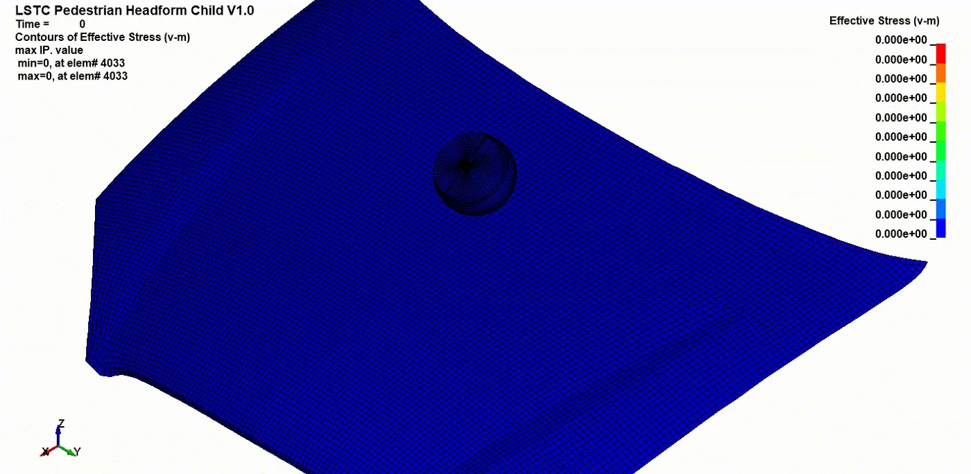
As mentioned, the same headform is used with positioning regulations of adult headform to perform the same pedestrian headform impact analysis.
Stress and strains:
The Adult headform is a bit bigger and heavier compared to child headform as a result, the output we get from this analysis would be undercutting the actual analysis results.
The peak stress is almost similar to case 2 but due to a much direct impact angle, and a larger contact area, the distribution of stresses is better with less concentration areas.
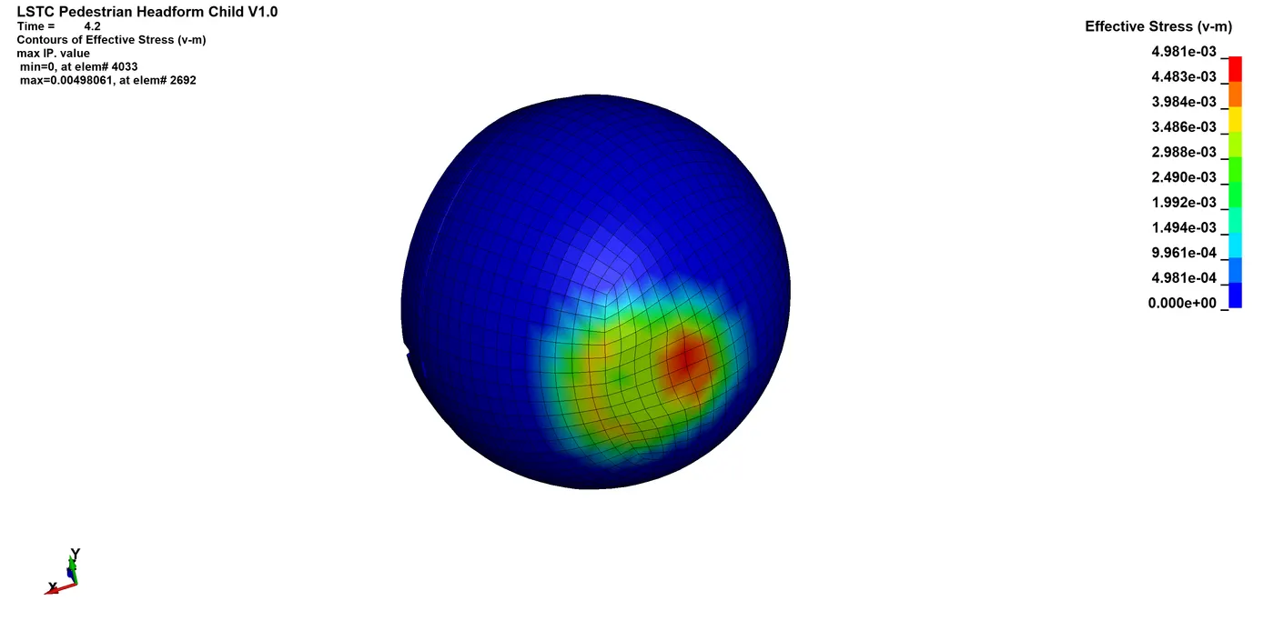
The peaks however settle down to almost identical stress value of 3.9MPa.
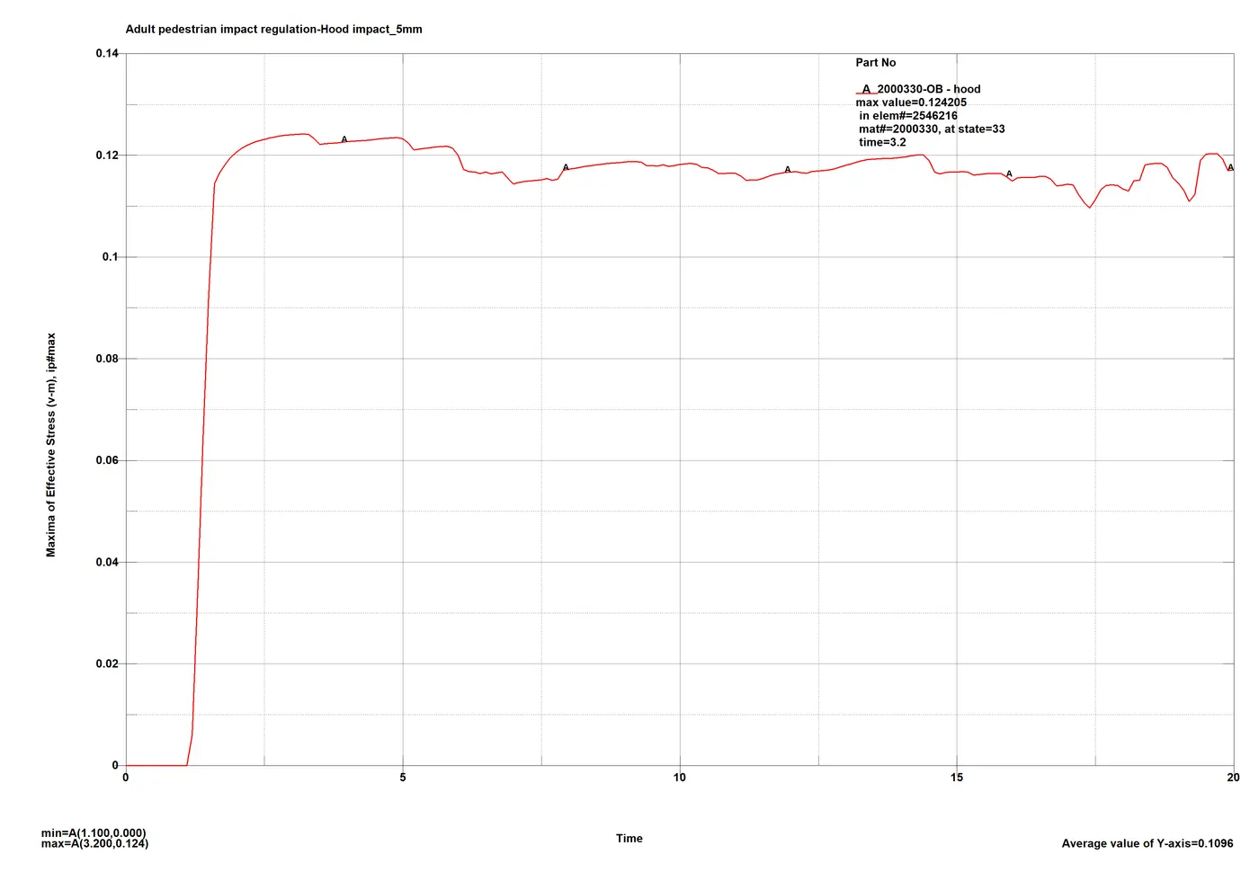
The similarities continue on the hood part, with similar results. A less stiff hood takes up a portion of the K.E. and deforms with a peak stress of 124.2 MPa.
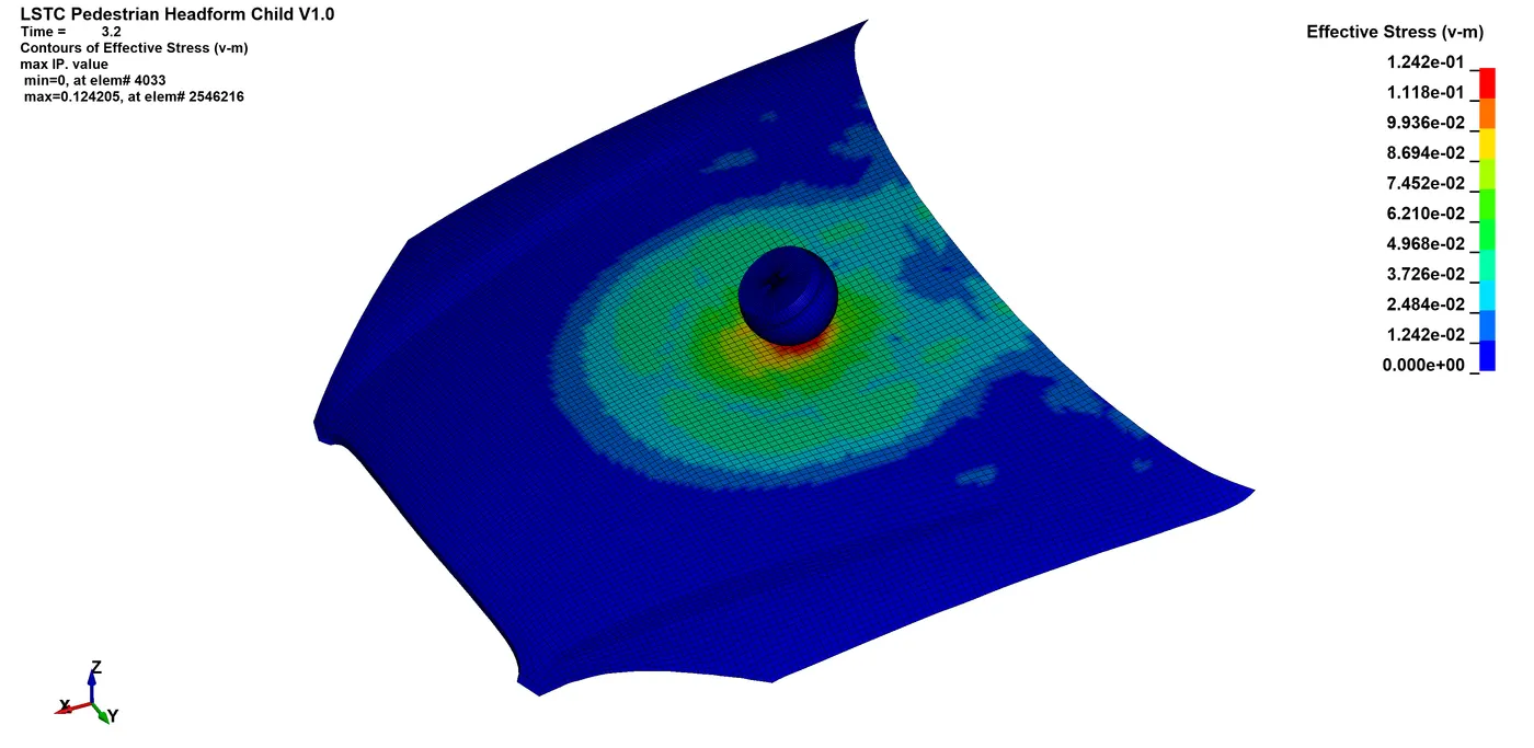
The stress wave propagates throughout the hood model and never actually settles down, hovering around the peak value till the end.
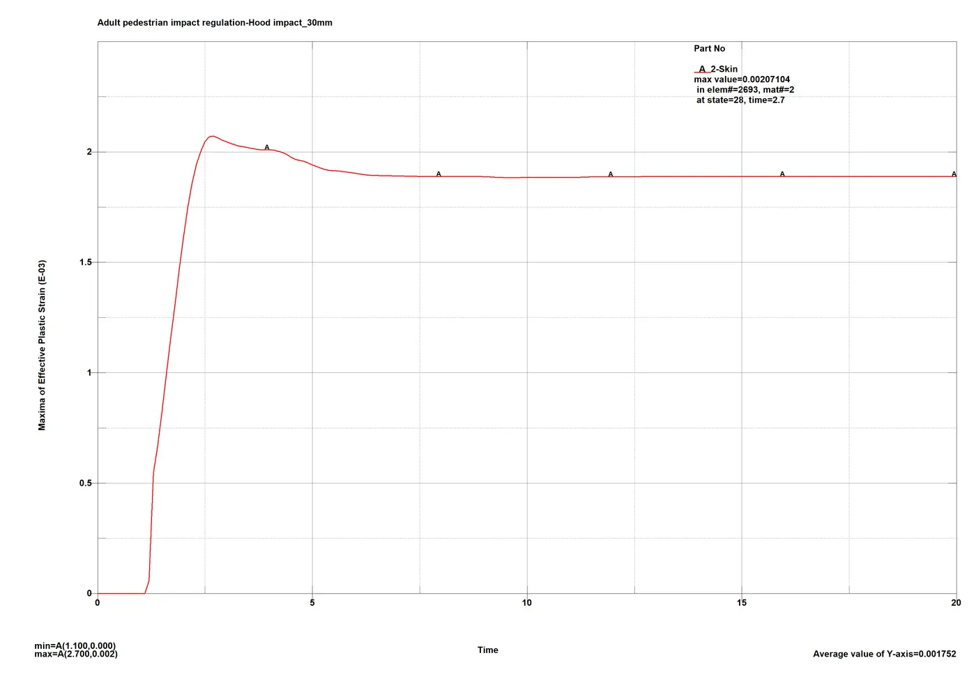
Similar results for the strains were recorded as expected with the peak strain at 0.2071% at the impact point.
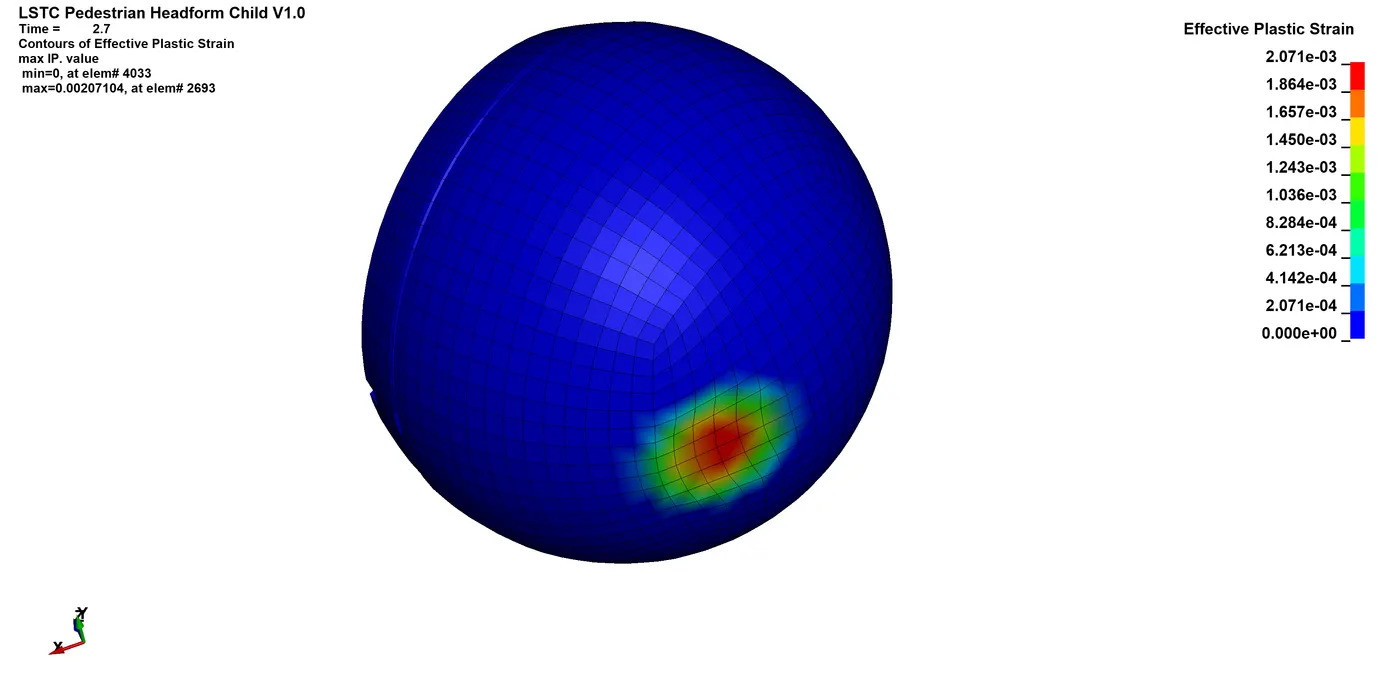
The strain peaks die down and settle at around 0.185% of permanent deformation.
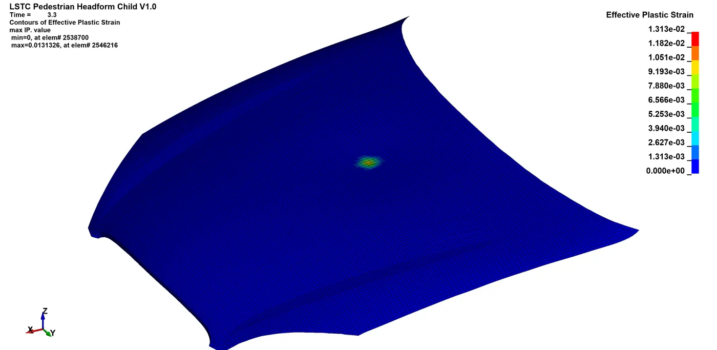
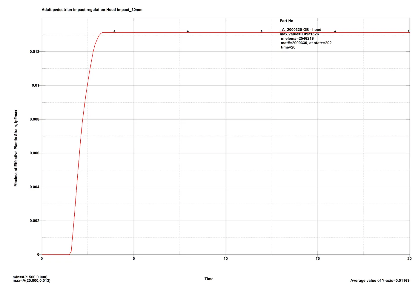
At the hood the strain is around 1.3% at peak with permanent deformation at the area of contact.
Energy plot:
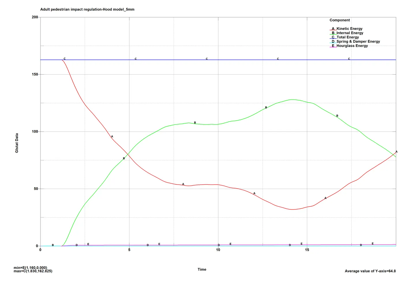
As seen above very small amount of plastic deformation is recorded at the end, which suggests the elastic nature of the majority deformation. The constraints at the support hinges and hood create a trampoline like effect and launch the headform over post impact. This can be seen from the energy plot as well as after the initial bump similar to case 2, the plots linearly accelerate and cross each other once again at the end of the simulation.
Acceleration plots:
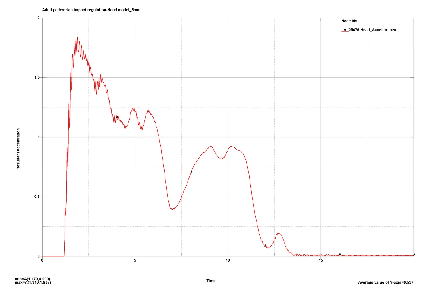
The 2 stages in the analysis - at the impact and after the impact are indicated by the 2 peaks, 1st one around 2.4ms and the 2nd one around 10ms. The peak figure is just a bit lower compared to case 2 at 1.83mm/ms2 and similarly the HIC3 figure would be more relevant than the others considering the peak range.
HIC3:
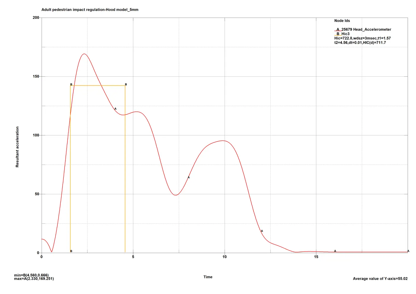
A considerable figure as per the regulations of 722.8 is recorded which marks the hood model as safe for the given regulation as it is within the limit of max <=1000 for green zone giving maximum points compared to case 2 results in orange zone with limit of max <=1400.
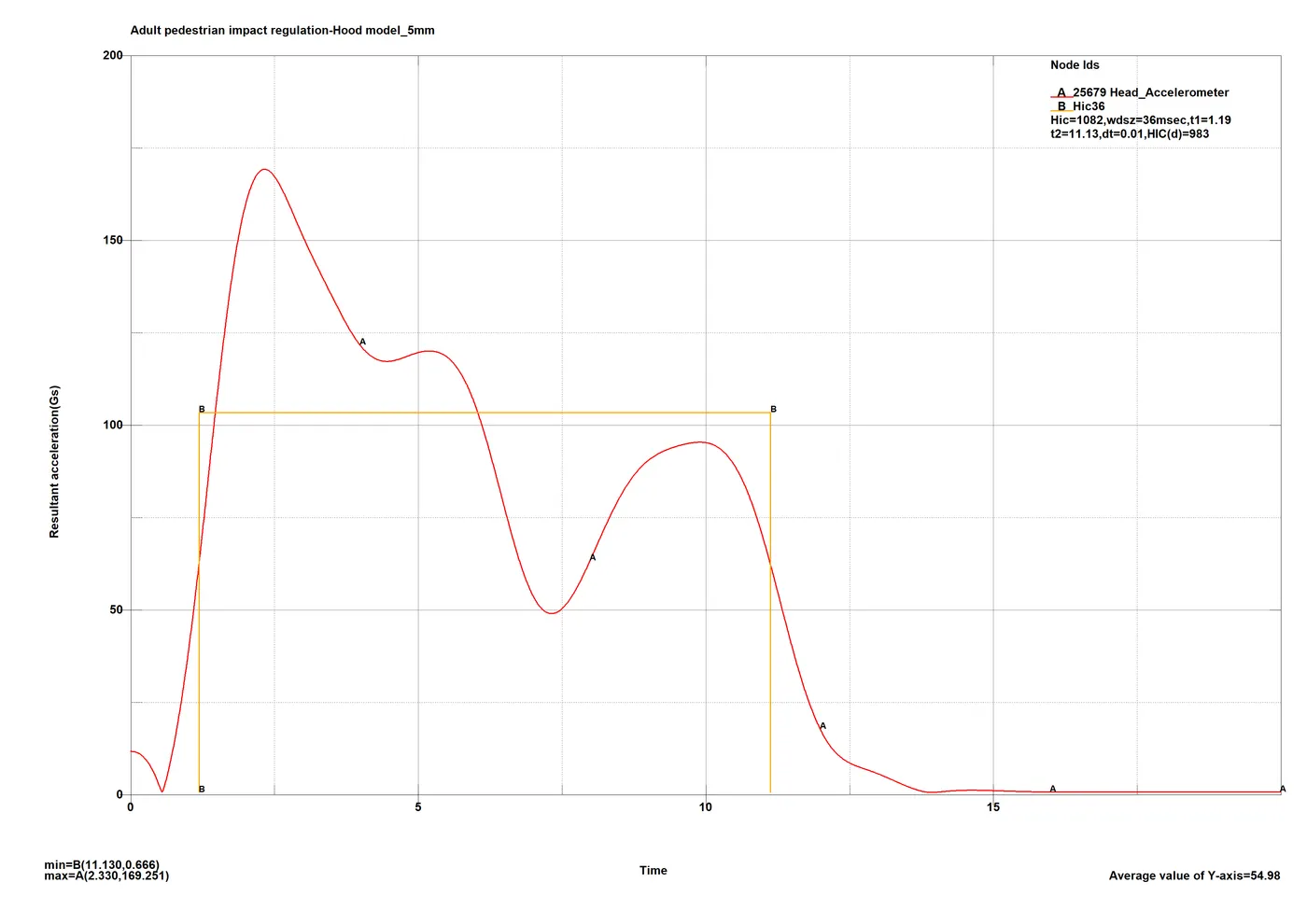
Similar to previous case, the peaks don’t last long for HIC15 and HIC36 to be considerable.
HIC15:
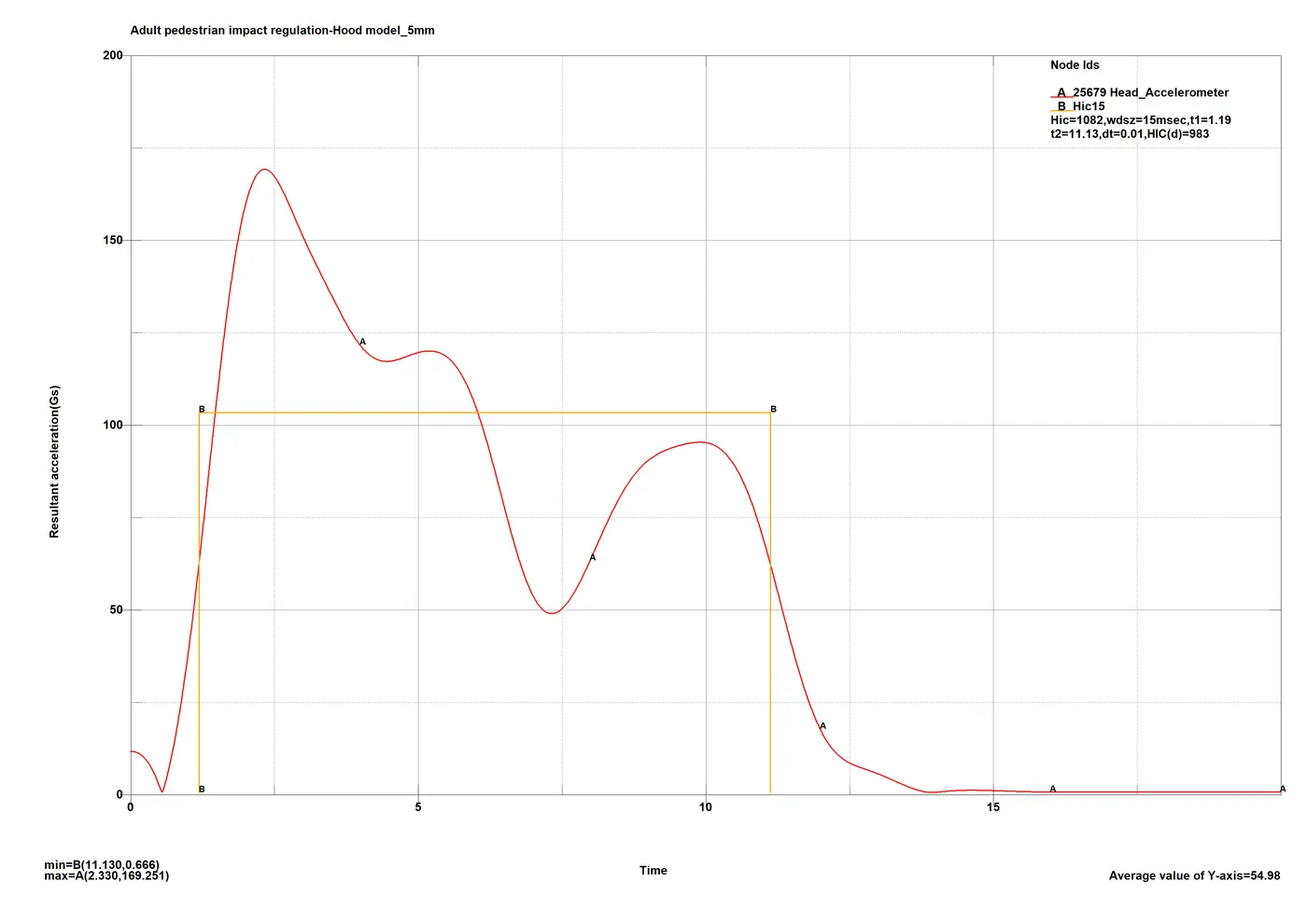
Even though not considerable and inaccurate, the values for both HIC15 and HIC36 are very low when compared to case 2, and are low enough to get a satisfactory pass as well.
HIC36:
Conclusion:
- As stated in the objective of the project, the results of the analysis are good for a case study of the procedure of the regulatory test. Even though they are not accurate due to the simplicity of the models lacking details, the results are good starting point and fulfil the understanding point.
- A more detailed model of the hood is required for even better/accurate results, but comparison of results for case 1: rigid wall impact and case 2: impact with hood model, make it very clear why such regulations are necessary and how making a part a bit more compliant can make difference. The drastic difference between stresses, and more importantly the acceleration figures and HIC parameters proves the point for thin panelled hoods with structural inner panels instead of rigid structures.
- The comparison between case 2 and 3 puts emphasis on accuracy and importance of standard impactor models in our case the headforms, as inaccurate model with accurate regulations application will give wrong judgement which will be dangerous in any crash analysis domain.