Week 7 - Creating connection for Rear door
Connections in Side Door
1. Introduction:
In a car side door, there are number of mechanisms, which are required to be modelled accurately.
The connections which are primarily to be defined is as follows:
1. 1. Door Hinge
2. 2. Door Latching mechanism
3. 3. All bolted connections
4. 4. Welded Connections
5. 5. Glass Rail Guide mechanism
6. 6. Whether strip connection
7. 7. Door Handle mechanism
For modelling all the above-mentioned connections, different types of elements viz, RBE2, RBE3 etc are used which is in detail discussed in this project report
2. PID SEPERATION:
The Initial FE model provided as one common PID for the entire door element. However, This is divided in to multiple PID and then the connections are achieved.
|
|
|
|
Initial Model – Single PID |
Final Model – with Separated PID |
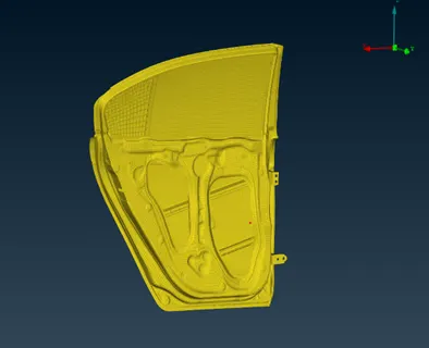
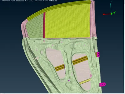
Once this separation of PID is made it becomes a bit convenient to understand the child part of the entire assembly.
1. HINGE CONNCETION:
The door of the car is hinged in order have a rotational DOF along one of the axes. In this example the door is rotating about the Z axis. Hence, to model the hinge connection in the door there are two types of RBE elements with different DOF is to be defined.
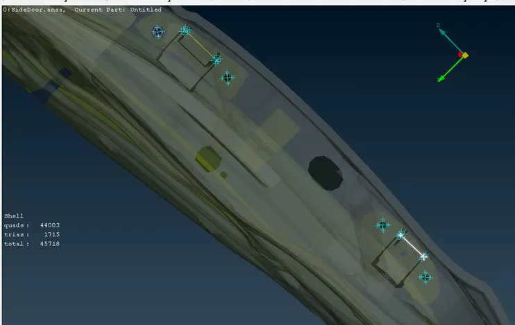
Here in order to define the car door hinge about 10 RBE-2 elements are used. Out of which 2 elements have constrained DOF = 5. One unconstrained DOF helps the door to rotate about vertical Z- axis
1. Door Latch Mechanism:
The door latch is connected with the latch wire. This region is modelled using RBE-2 element.
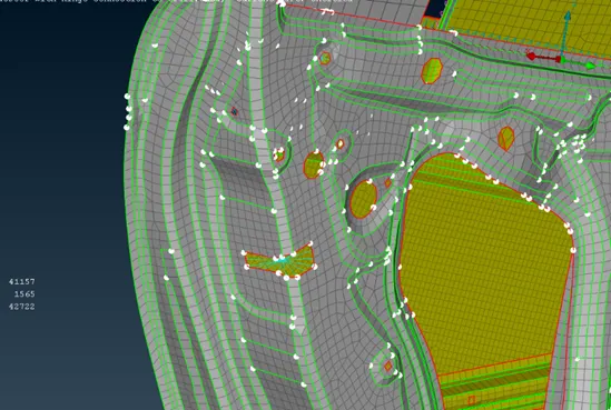
1. Bolt Connection:
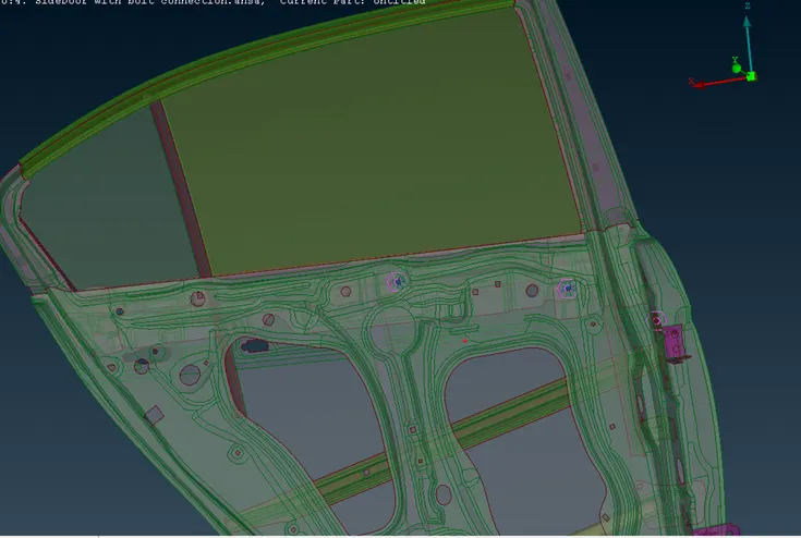
As we can see in the above image, 3 bolts connections are defined. However, there are in
Total 4 bolt connection but one of them is done using RBE-2 element(experimenting).
Bolting connection is done using following steps:
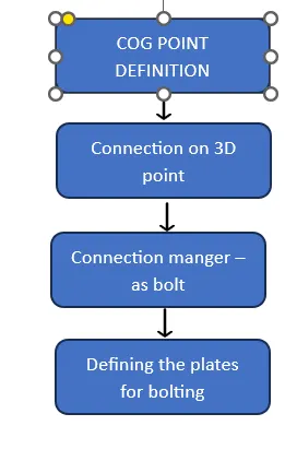
1. 6. WHETHER STRIP MODELLING:
The glass in the vehicle door is supported using the EPDM strips on the borders of the glasses. However, this has to be defined as a separate connection as there are the RBE-CBUSH elements are involved which has a stiffness value which is provided by the manufacturer. The connection type provided here is spot line.
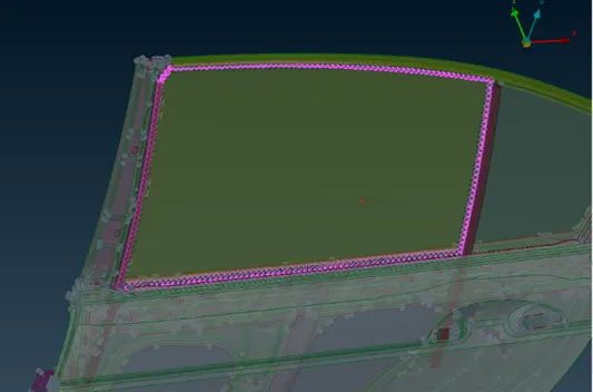
As we can see from the above image that all the four sides of the glass are given a CBUSH connection. In this example the stiffness is randomly is taken and defined in the property card.RBE-3 elements have stiffness in all the three directions.
However, In the bottom part of the glass, the whether strip is to be modelled on the both side of the glass, which helps in the proper motion of the glass through the guide.
1. HANDLE MODELLING
The modelling of the handle door is in two steps.
Step-1: RBE 2 element is used as rigid connection in the handle slots & RBE 2 two nodes is selected in order to connect the two RBE 2 element.
Step -2: The COG is defined in the two node RBE 2 elements.
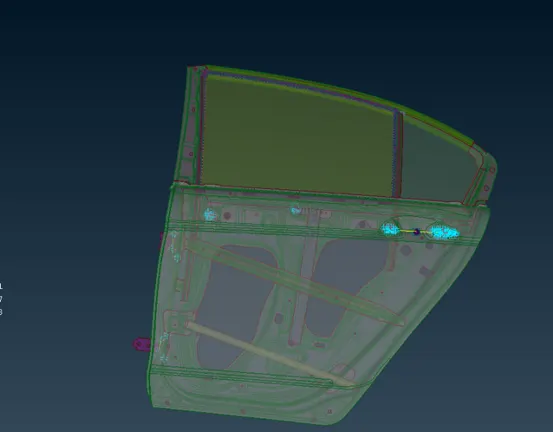
Here the mass is defined using the mass property card. In this case the mass is randomly taken as 0.01 tons = 10 Kg
1. SPOT WELDING
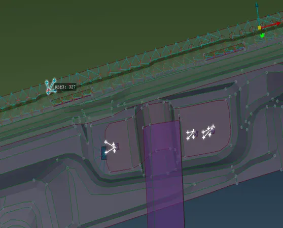
The hinge is spot welded with the sheet metal plate using RBE-3 element.
Learning & Outcomes
|
Sr no |
Mechanism |
Element used |
Connection type |
|
1 |
Whether strip |
C-Bush |
Spot line |
|
2 |
Hinge |
RBE-2 |
Bolt |
|
3 |
Latch |
RBE-2 |
Bolt |
|
4 |
Glass guide rail |
RBE-3 |
Spot weld |
|
5 |
Door Handle |
RBE-2 |
COM |
Apart from the above mechanisms & Elements following are the learnings:
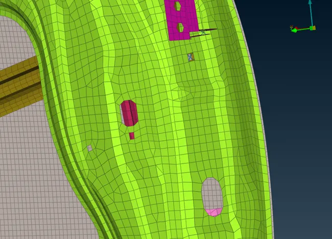
TAYLOR WELD MODEL: The region in which the hinge is present has a higher thickness as compared to the adjacent region. This variational thickness door model helps in cost cutting as well as the weight reduction.
Local Vector Direction: of CBUSH: Initially when the C- Bush elements were introduced, their direction was similar to the global coordinate system, As per the latest guidelines, the direction of C Bush is needed to be aligned with the Global Co-ordinates.
CHECK ARM: The Door check arm is responsible for allowing the door to open in a particular angle. The Altroz has check arm, which helps it to open almost up to 90 degrees
1. Conclusion:
From this project it can be concluded that, the connections in any model is a mandatary requirement for modelling all the mechanisms of model accurately by controlling the values of parameters viz. DOF, Stiffness, mass etc